heating HONDA CIVIC 2000 6.G Workshop Manual
[x] Cancel search | Manufacturer: HONDA, Model Year: 2000, Model line: CIVIC, Model: HONDA CIVIC 2000 6.GPages: 2189, PDF Size: 69.39 MB
Page 353 of 2189

Troubleshooting
Troubleshooting Procedures (cont,dl
CAUTION:
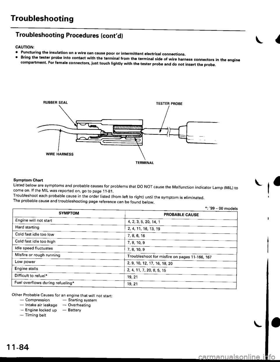
. Punqturing ihe insulation on a wirs can cause poor or intermiftent electricar connections.I Bring the test€r probe into contacl with the terminatlrom the terminal side of wire harnesg conncctors in the gngin€compartment. For temale connectors, iust touch lightly with the tester probe and do not inse.t the probe.
\I
RUBBER SEAL
Other Probable Causes for an engine that will not start:- Compression- Starting system- lntake air leakage - Overheating- Engine locked up - Battery- Timing belt
TESTER PROBE
Symptom Chart
Listed below are symptoms and probable causes for problems that Do NoT cause the Malfunction indicator Lamp (MlL) tocome on. lfthe MIL was reported on, go to page 11_81.Troubleshoot each probabre cause in the order risted (from reft to right) untir the symptom is eriminated.The probable cause and troubleshooting page reference can be found berow.
L
*: '99 - 00 models
TERMINAL
SYMPTOMPROBABLE CAUSE
4,2,3, 5,20, 14, 1
2, 4, 11, 16, 13, 't9
?, s^6. 16
1,8,10.9
Engine will not sta rt
Hard starting
Cold fast idle too low
Cold fast idle too high
ldle speed fluctuates7,8, 10.9
Troubleshoot for misfire on pages l1-166, 167Misfire or rough running
LOW power
E"g|* "t"lb
2,9, 10, 12, 11, 16, 't8,20
2,4,11,7,20,8,5,15
't9, 21
1r, ,1
Difficult to refuel*
Fuel overflows during refueling*
11-84
Page 1090 of 2189

lnspection and Adjustment
Pump Pressure Check
Check the fluid pressure as follows to determine
whether the trouble is in the pump or gearbox.
NOTE: First check the power steering fluid level andpump belt tension.
CAUTION: Disconnect the high pr$sure hos€ with care
so as not lo spill the power sieering tluid on tha frame
and other parts.
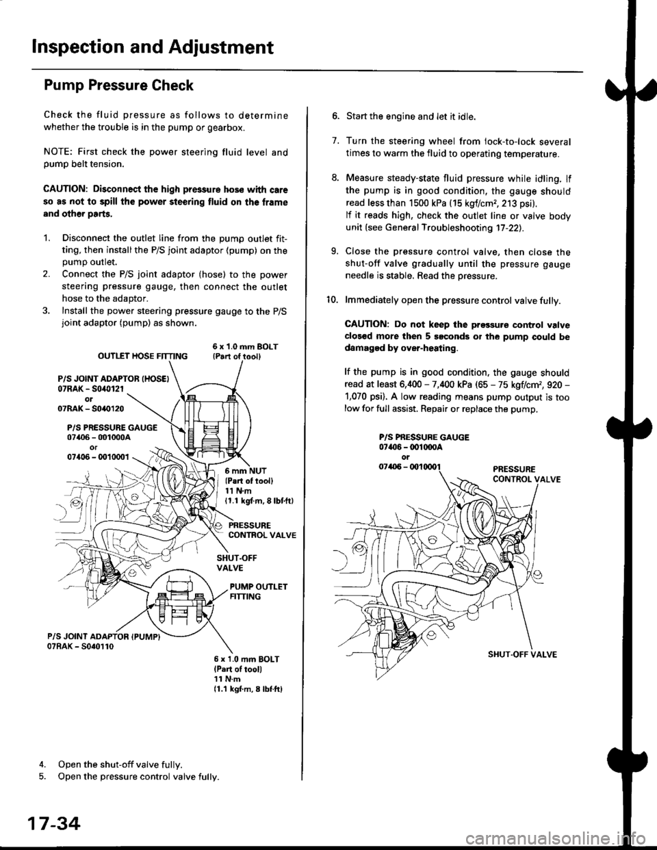
1. Disconnect the outlet line from the Dumo outlet fit-
ting, then installthe P/S joint adaptor (pump) on the
Dumo outlet.
2. Connect the P/S joint adaptor (hose) to the power
steering pressure gauge, then connect the outlet
hose to the adaptor.
3. Install the power steering pressure gauge to the P/Sjoint adaptor (pump) as shown.
ourlEr HosE FnrNo ,t"ll lrilu"ott
P/S JOINT ADAPTOB IHOSEI07RAK - S0i10l2rol07RAK- 50{{)120
P/S PRESSURE GAUGE07406 - 001000Aor07406 - 0010001
4. Open the shut-off valve fully.
5. Open the pressure control valve fully.
17-34
(Pa.t of tooll11 N.m11.1 kgt m, 8 lbf.ftl
PRESSURECONTROL VALVE
SHUT.OFFVALVE
PUMP OUTLETFITTING
6 x 1.0 mm BOLTlPart of tool)11 N.m11.1 kgf m, 8 lbtftl
7.
Start the engine and let it idle.
Turn the steering wheel from lock-to-lock several
times to warm the fluid to operating temperature.
Measure steady-state fluid pressure while idling. If
the pump is in good condition, the gauge should
read less than 1500 kPa (15 kgf/cmr, 213 psi).
lf it reads high, check the outlet line or valve body
unit (see General Troubleshooting 17-22).
Close the pressure control valve, then close the
shut-off valve gradually until the pressure gauge
needle is stable. Read the oressure.
lmmediately open the pressure control valve fully.
GAUTION: Do not keep lhe prossure control valve
clos€d more then 5 soconds or the pump could be
damagod by over-heating.
lf the pump is in good condition, the gauge should
read at least 6,400 - 7,400 kPa (65 - 75 kgflcm,, 920 -
1,070 psi). A low reading means pump output is too
low for full assist. Repair or replace the pump,
9.
P/S PBESSURE GAUGE07{16 -@1@OA
oi
SI{UT.OFF VALVE
Page 1334 of 2189

Door and Side Moldings
Replacement (cont'dl
Door molding removal:
The following materials and tools are required to repairthe door moldings.
NOTE: Followthe manufacturer's instructions.
Materials: (Reference)
. Stripe remover
3M 08907
Stripe adhesive remover
3M 08908
Adhesive tape
3M Super Automotive Attachment Tape
Tools;
a Protective tape
. Knife or Cutter
. Sponge or Shop towel. Infrared dryer
. Film
. Putty knife
. Alcohol
CAUTION: Put on gloves to protect your hands,
Remove the door panel, and pull back the plastic
cover,
Apply protective tape on and around the molding.
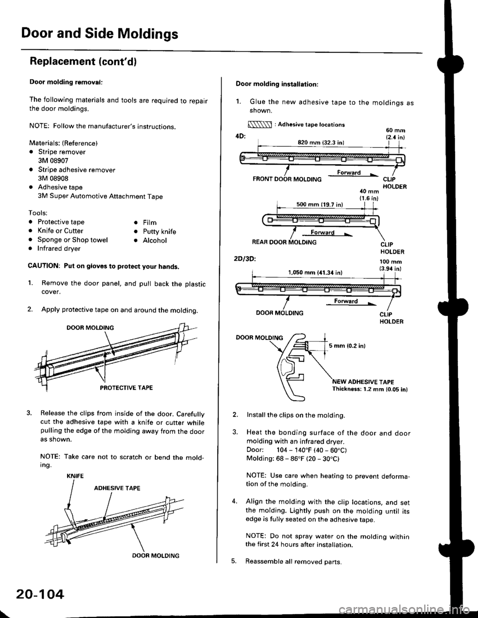
3. Release the clips from inside of the door. Carefullvcut the adhesive tape with a knife or cutter whilepulling the edge of the molding away trom the dooras shown.
NOTE: Take care not to scratch or bend the mold-Ing.
1.
KNIFE
DOOR MOLDING
\
20-104
Door molding installation:
1. Glue the new adhesive tape to the moldings assnown.
[\\\l : Adhesive tape tocations60 mm4D: t2 t i^l
40 mm11.6 in)
Forward L
REAR DOOR
2Dl3Dl
CLIPHOLDER
100 mm(3.94 inl1,050 mm 141.34 inl
Forward !
DOOR MOLDING
DOOR MOLDING
5 mm {0.2 inl
ADHESIVE TAPEThickness: 1.2 mm 10.05 in)
Installthe clips on the molding.
Heat the bonding surface of the door and doormolding with an infrared dryer.
Door: 104 - 140"F (40 - 60.C)Molding: 68 - 86"F (20 - 30.C)
NOTE: Use care when heating to prevent deforma-tion of the molding.
Align the molding with the clip locations, and setthe molding. Lightly push on the molding until itsedge is fully seated on the adhesive tape.
NOTE: Do not spray water on the motding withinthe first 24 hours after installation.
Reassemble all removed pans.
Page 1594 of 2189

Gharging System
Rear Bearing Replacement
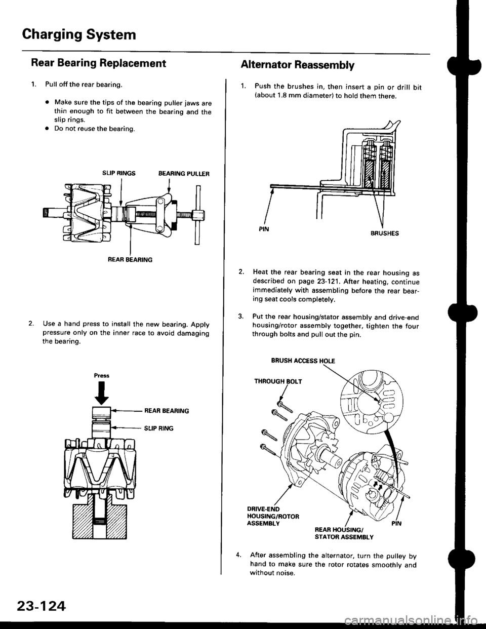
1. Pull offthe rear bearing,
. Make sure the tips of the bearing puller jaws arethin enough to fit between the bearing and theslip rings.
. Do not reuse the bearing.
SLIP RINGSBEARING PULLER
Use a hand press to install the new bearing. Applypressure only on the inner race to avoid damaging
the bearino.
REAB BEARING
23-124
Alternator Reassembly
1. Push the brushes in, then insert a pin or drill bit(about 1.8 mm diameter) to hold them there.
Heat the rear bearing seat in the rear housing asdescribed on page 23-121. After heating, continueimmediately with assembling before the rear bear-ing seat cools completely,
Put the rear housing/stator assembly and drive-endhousing/rotor assembly together. tighten the fourthrough bolts and pull out the pin.
REARSTATOR ASSEMBLY
After assembling the alternator, turn the pulley byhand to make sure the rotor rotates smoothlv andwithout noise.
BRUSHES
THROUGH BOLT
Iq
%*z
BRUSH AOCESS HOI."E