Control HONDA CIVIC 2003 7.G Workshop Manual
[x] Cancel search | Manufacturer: HONDA, Model Year: 2003, Model line: CIVIC, Model: HONDA CIVIC 2003 7.GPages: 1139, PDF Size: 28.19 MB
Page 937 of 1139
Rear Window Defogger
Function Test
NOTE:. Be careful not to scratch or damage the defogger
wires with the tester probe.
. Before testing, check the No. 11 (30A) fuse in the
under-hood fuse/relay box and No. '14 ('10A) fuse in
the under-dash fuse/relay box.
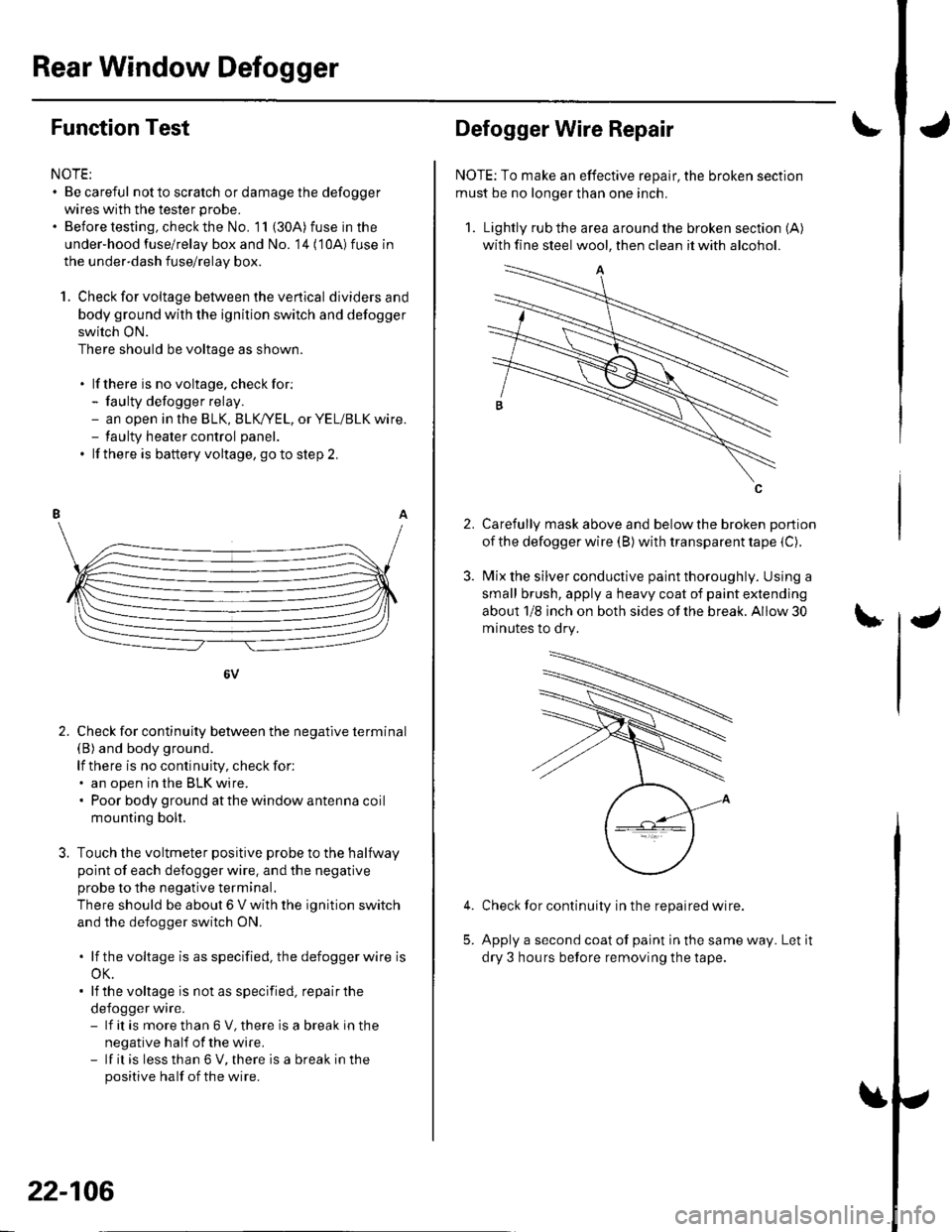
1. Check for voltage between the ve rtica I dividersand
body ground with the ignition switch and defogger
switch ON.
There should be voltage as shown.
. lf there is no voltage. checkfor:- faulty defogger relay.- an open in the BLK, BLK,/YEL, or YEL/BLK wire.- taulty heater control panel.
. lf there is battery voltage, goto step 2.
6V
Check for continuity between the negative terminal(B) and body ground.
lf there is no continuity, check for:. an open in the BLK wire.. Poor body ground at the window antenna coil
mounting bolt.
Touch the voltmeter positive probe to the halfway
point of each defogger wire. and the negative
probe to the negative terminal,
There should be about 6 V with the ignition switch
and the defogger switch ON.
. lf thevoltage is asspecified, the defoggerwlre is
oK.. lf the voltage is not as specified, repair the
defogger wire.- lf it is more than 6 V, there is a break in the
negative half of the wire.- lf it is less than 6 V, there is a break in the
positive half of the wire.
2.
22-106
2.
Defogger Wire Repair
NOTE: To make an effective repair, the broken section
must be no longer than one inch.
1. Lightly rub the area around the broken section (A)
with fine steel wool, then clean it with alcohol.
Carefully mask above and below the broken portion
of the defogger wire (B) with transparent tape {C).
Mix the silver conductive paint thoroughly. Using a
small brush, apply a heavy coat of paint extending
about 1/8 inch on both sides of the break. Allow 30
minutes to dry.
Check for continuity in the repaired wire.
Apply a second coat of paint in the same way. Let it
dry 3 hours before removing the tape.
5.
Page 939 of 1139
Moonroof
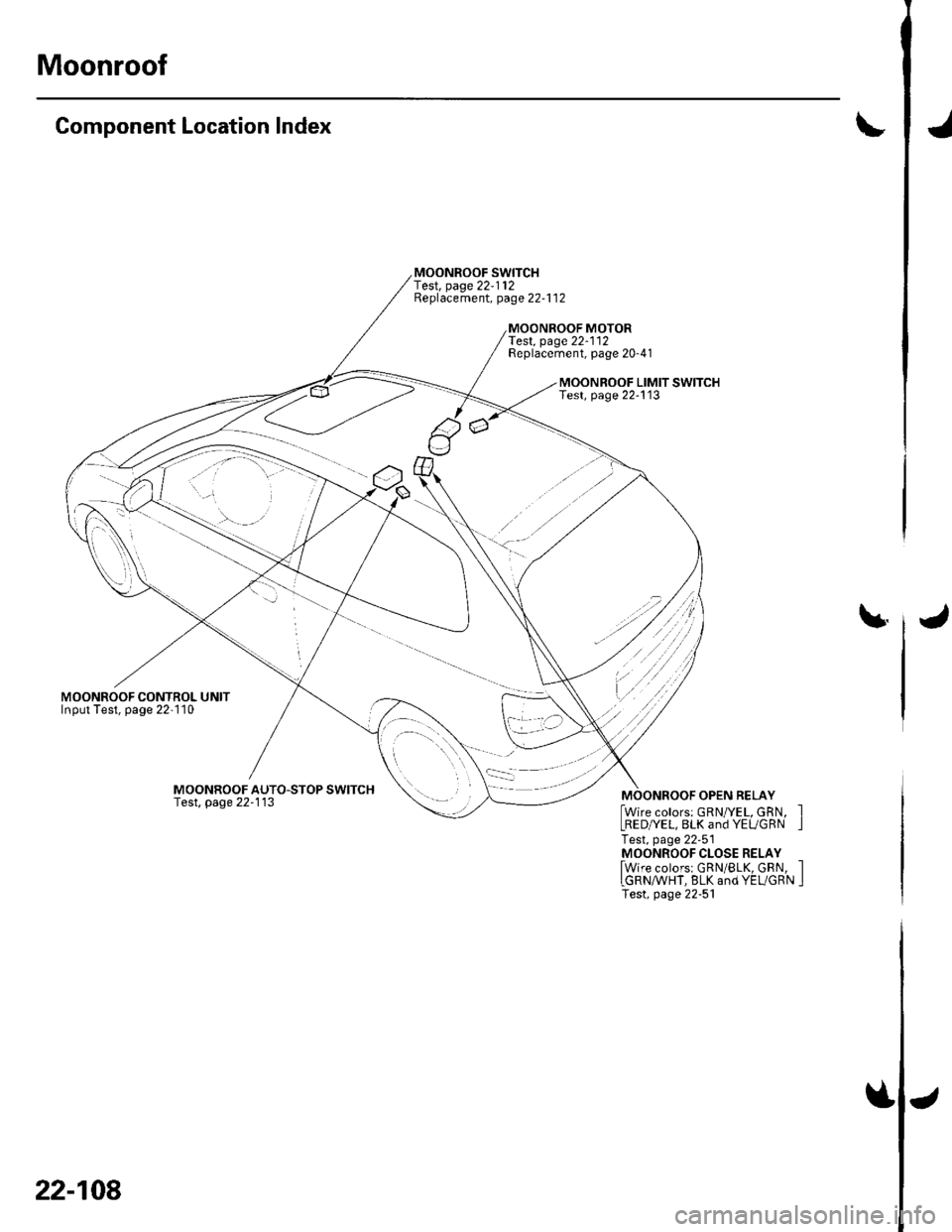
Component Location Index
MOONROOF CONTROL UNITInput Test, page 22-'l10
MOONROOF SWITCHf e$, page 22-112Replacement, page 22-1 12
Test. page22-112Replacement, page 20-41
MOONROOF LIMIT SWITCHTest, page 22-113
\|.
MOONROOF AUTO-STOP SWITCHTest, page 22'113MOONROOF OPEN RELAY
lwire colors: GRN/YEL, GRN, ILRED/YEL, BLK and YEUGRN ITest, page 22-51MOONROOF CLOSE RELAY
lwire colorsr GRN/BLK, GRN, ILGRN/WHT, BLK and YEL/GRN ITest, page 22-51
22-108
Page 941 of 1139
Moonroof
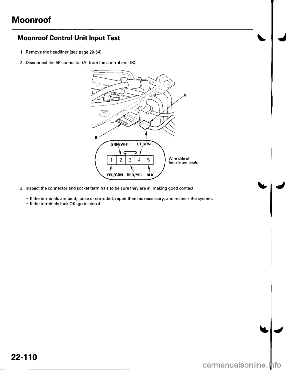
Moonroof Control Unit Input Test
Remove the headliner (see page 20-54).
Disconnect the 5P connector (A) from the control unit (B).
Wire side offemale terminals
Inspect the connector and socket terminals to be sure they are all making good contact.
. lf the terminals are bent, loose or corroded, repairthem asnecessary. and recheckthe system.. lf the terminals look OK, go to step 4.
IJ
1.
2.
bJ
GRN/WHT LT GRN
12345
RED/YEL BLK
22-110
$J
Page 942 of 1139
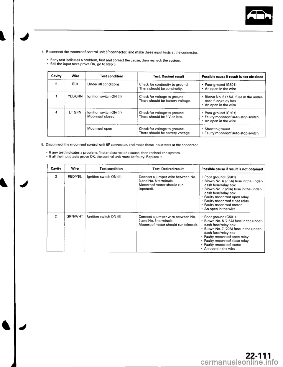
4- Reconnect the moonrool control unit 5Pconnector, and makethese inputtests attheconnector.
.lfanytestindicatesaproblem,findandcorrectthecause,thenrecheckthesystem.. lf all the input tests prove OK, go to step 5.
CaviiyWireTest conditionTest: Desired resuhPossible caus6 if result is not obtained
5BLKUnder allconditionsCheck for continuity to ground:There should be continuity.Poor ground (G501)An open in the wire
,lYEUGRNlgnition switch ON (ll)Check for voltage to ground:There should be baftery voltage.Blown No. 6 (7.54)tuse in the underdash fuse/relay boxAn open in the wire
LT GRNlgnition switch ON (ll)MoonroofclosedCheck for voltage to ground:There should be 1V or less.Poor ground (G501)Faulty moonroof auto-stop switchAn open inthewire
Moonroof openCheck for voltage to ground:There should be battery voltage.Shortto groundFaulty moonroof auto-stop switch
Disconnectthe moonroof control unit 5Pconnector, and make these;nputtests at the connector
'lfanytestindicatesaproblem,findandcorrectthecause,thenrecheckthesystem.. lf all the inputtests prove OK, the control unit must befaultv. Replace it.
CavityWireTest conditionTest: Desired rosultPossible cause if result is not obtained
3RED//ELlgnition switch ON lll)Connect a jumper wire between No,3 and No. 5 terminals.Moonroof motor should run(opened).
Poorground (G501)Blown No. 6 (7.5Aifuse in the under'dash fuse/relay boxBlown No.7120Alfuse inthe underdash fuse/relay boxFaulty moonroof open relayFaulty moonroof close relayFaulty moonrooJ motorAn open;n thewire
2cRN,4/VHTlgnition switch ON (ll)Connect a jumper wire between No.2 and No. 5 terminals.I\,4oonroof motor should run {closed).
Poor ground (G501)Blown No. 6 (7.5Aifuse in the underdash fuse/relay boxElown No. 7 (20A)fuse in the underdash fuse/relay boxFaulty moonroof open relayFaulty moonrool close relayFaulty moonroof motorAn open in the wire
22-111
Page 957 of 1139
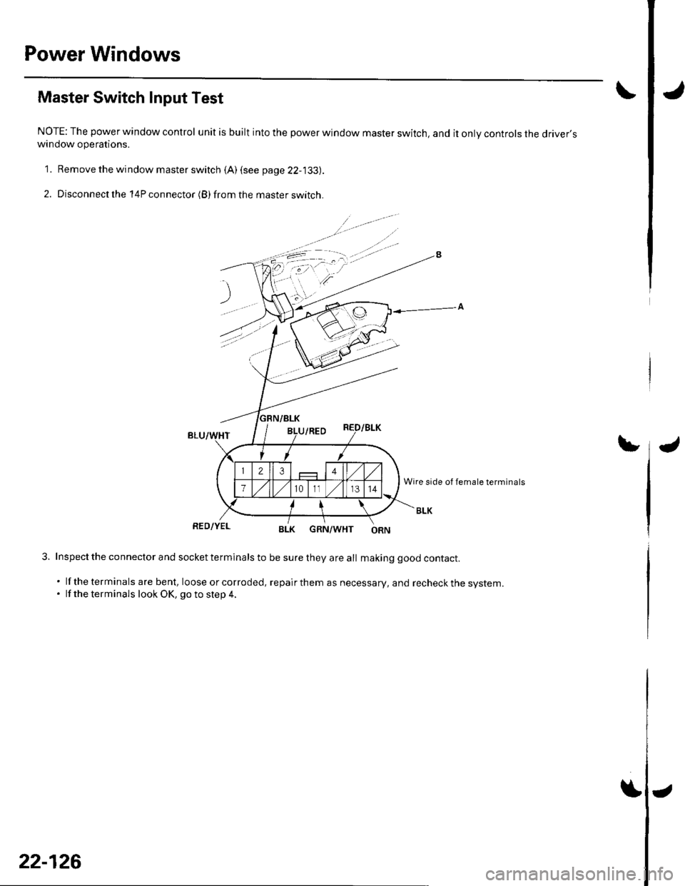
Power Windows
Master Switch Input Test
NOTE: The power window control unit is built into the power window master switch, and it only controls the driver'swindow operations.
1. Remove the window master switch {A) (see page 22-133).
2. Disconnect the 14P connector (B) from the master switch.
GRN/WHT
3. Inspect the co nnector and socket terminals to be sure they are all making good contact.
. lf theterminals are bent, loose orcorroded, repairthem as necessary, and recheckthe system.. lf the terminals look OK, go to step 4.
22-126
Page 958 of 1139
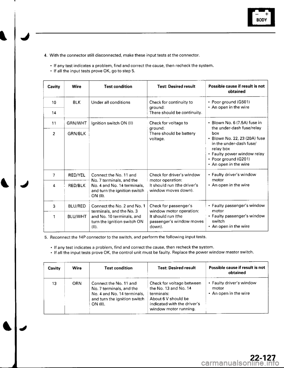
4. Withthe connector still disconnected, makethese inputtests attheconnector.
.lfanytestindicatesaproblem,findandcorrectthecause.thenrecheckthesystem.
. lf allthe inputtests prove OK, goto step 5.
5. Reconnect the 14P connector to the switch, and perform the following input tests.
.lfanytestindicatesaproblem,findandcorrectthecause,thenrecheckthesystem.
. lf all the input tests prove OK, the control unit must be faulty. Replace the power window master switch.
CavityWireTest conditionTest: Desired resultPossible cause if result is not
obtained
10BLKUnder all conditionsCheck for continuity to
grouno:
There should be continuity.
. Poor ground {G50'1). An open in the wire
14
11G RN^,^/HTlgnition switch ON (ll)Check for voltage to
ground:
There should be battery
voltage.
Blown No.6 (7.5A) fuse in
the under-dash fuse/relay
box
Blown No. 22,23 l2OA) tuse
in the under-dash fuse/
relay Dox
Faulty power window relay
Poor ground (G201)
An open in the wire
2GRN/BLK
1RED/YELConnect the No. 'l'1 and
No. 7 terminals, and the
No, 4 and No. 14 terminals,
and turn the ignition switch
oN flr).
Check for driver's window
molor operaflon:
It should run (the driver's
window moves down).
. Faulty driver's window
motor. An open in the wireRED/B LK
3BLU/REDConnect the No. 2 and No. 1
terminals, and the No. 3
and No. 10 terminals, and
turn the ignition switch ON
fi r),
Check for passenger's
window motor operation:
It should run (the
passenger's window moves
oown).
Faulty passenger's window
motor
Faulty passenger's window
swatch
An open in the wire
BLU/WHT
CavityWireTest conditionTest: Desired resultPossible cause if result is not
obtained
13ORNConnect the No. 11 and
No. 7 terminals, and the
No. 4 and No. 14 terminals,
and turn the ignition switch
oN 0r).
Check for voltage between
the No. 13 and No. 14
termtnals:
About6Vshouldbe
indicated with the driver's
window motor running.
. Faulty driver's window
molor. An open in the wire
22-127
Page 965 of 1139
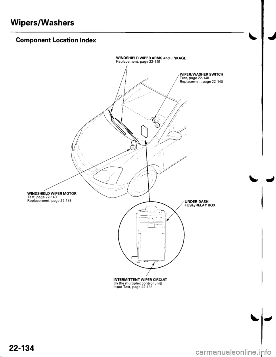
Wipers/Washers
Component Location Index
WINDSHIELD WIPER MOTORTest, page 22-'143Replacement, page 22-145
WINDSHIELD WIPER ARMS and LINKAGEReplacement, page 22-'145
WIPER/WASHER SWITCHTest, page 22-140Replacement,page 22 140
UNDER.DASHFUSE/RELAY BOX
INTERMITTENT WIPER CIRCUITlln the multiplex control unit)Input Test, page 22-138
22-134
Page 966 of 1139
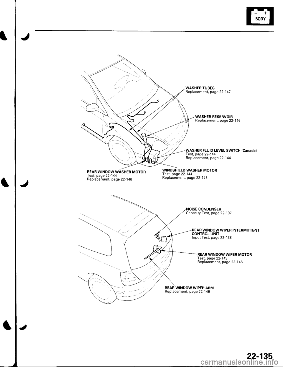
REAR WINOOW WASHER MOTORTest, page 22-144Replacement, page 22 146
WINDSHIELD WASHER MOTORfesl, page 22 144Beplacement, page 22-146
WASHER TUBESReplacement, page 22-147
CONDENSERCapacityTest, page 22 107
BEAR WINDOW WIPER ARMReplacement, page 22 146
WASHER RESERVOIBReplacement, page 22'146
WASHER FLUID LEVEL SWITCH {Canada)TesI, page22-144Replacement, page 22-144
REAR WINDOW WIPER INTERMITTENTCONTROL UNITInput Test, page 22'138
REAR WINDOW WIPER MOTORf e$, page 22-143Replacement, page 22 146
22-135
Page 969 of 1139
Wipers/Washers
1.
2.
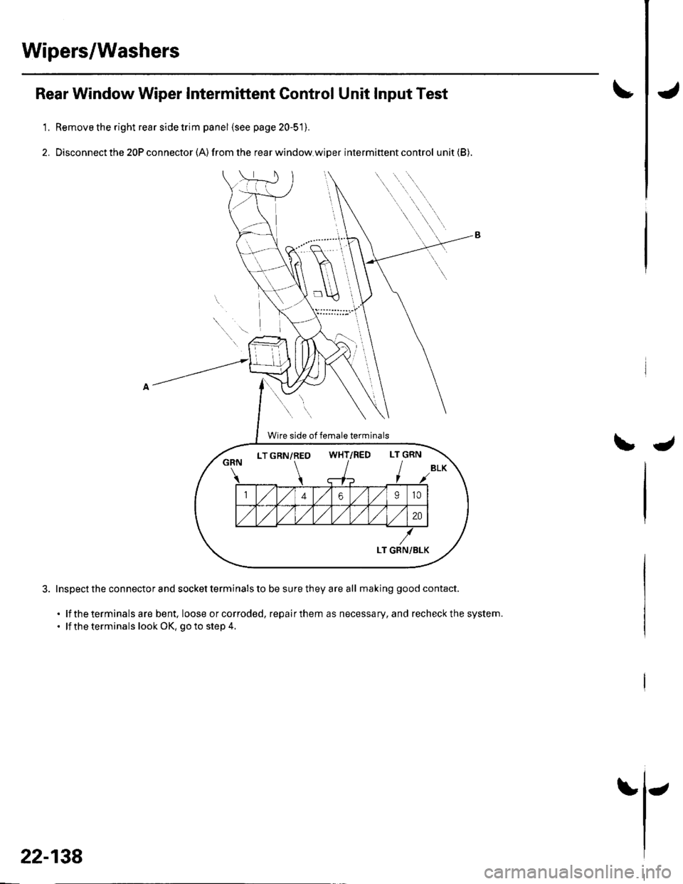
Rear Window Wiper Intermittent Gontrol Unit Input Test
Remove the right rear side trim panel {see page 20-51).
Disconnect the 20P connector (A) from the rear window.wiDer intermittent control unit (B).
Inspect the connector and socket terminals to be sure they are all making good contact.
. lf the terminals are bent, loose orcorroded, repairthem as necessary, and recheckthe system.. lf the terminals look OK, go to step 4.
Wire side of female terminals
LTGRN/REO WHT/RED LT GRNWHT/RED
LT GRN/BLK
22-138
Page 970 of 1139
\
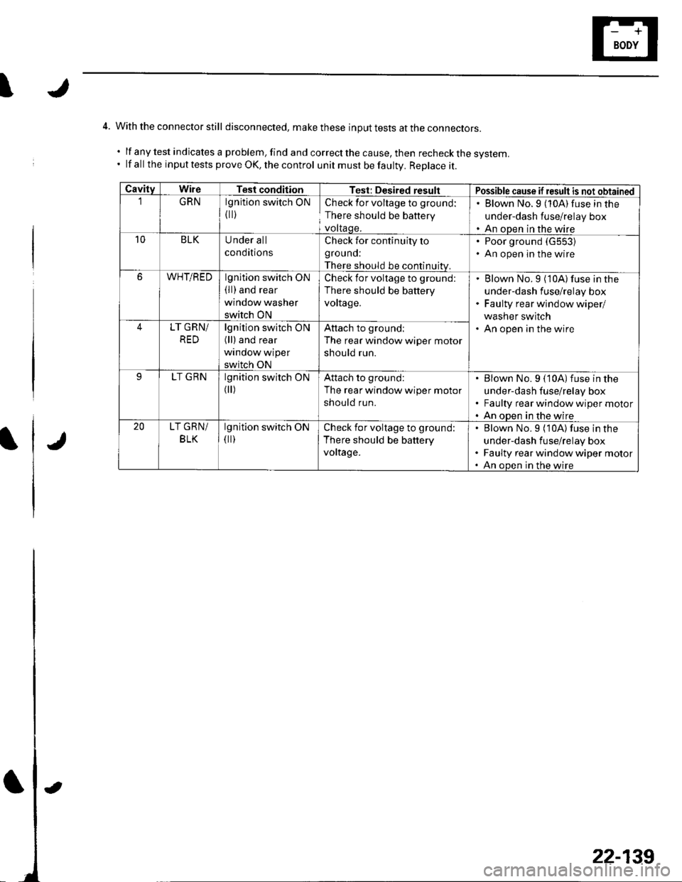
4. With the connector still disconnected, makethese input tests at the con necrors.
.lfanytestindicatesaproblem,findandcorrectthecause,thenrecheckthesystem.
' lf all the input tests prove OK, the control unit must be faultv. Replace it.
CavitvWireTesl conditionTest: Desired resultPossible cause if result is not obtainedGRNlgnition switch ON
flr)
Check for voltage to ground:
There should be battery
voltaqe.
. Blown No.9 (10A)fuse in the
under-dash fuse/relay box. An open in the wire10BLKUnder all
conditions
Check for continuity to
grouno:
There should be continuitv.
Poor ground (G553)
An open in the wire
6WHT/REDlgnition switch ON(ll) and rear
window washer
switch ON
Check for voltage to ground:
There should be battery
vortage.
Blown No.9 (10A) fuse in the
under-dash fuse/relay box
Faulty rear wlndow wiper/
washer switch
An open in the wire4LT GRN/
RED
lgnition switch ON(ll) and rear
window wiper
switch ON
Attach to groundl
The rear window wiper motor
should run.
LT GRNlgnition switch ON
flr)
Attach to ground:
The rear window wiper motor
should run.
Blown No. 9 (10A)fuse in the
under-dash fuse/relay box
Faulty rear window wiper motor
An open in the wire20LT GRN/
BLK
lgnition switch ON(ll)Check for voltage to ground:
There should be battery
voltage.
Blown No.9 (10A) fuse in the
under-dash fuse/relay box
Faulty rear window wiper motor
An oDen in the wire
22-139