HONDA CIVIC 2003 7.G Workshop Manual
Manufacturer: HONDA, Model Year: 2003, Model line: CIVIC, Model: HONDA CIVIC 2003 7.GPages: 1139, PDF Size: 28.19 MB
Page 361 of 1139
Fuel Supply System
Fuel Pulsation Damper Replacement
1. Relieve the fuel pressure(seepagell-144).
2. Remove the engine cover.
3. Remove the fuel rail mounting nuts from the fuelrail.
4. Remove the ground cable (G 101.
5. Raise the fuel rail.
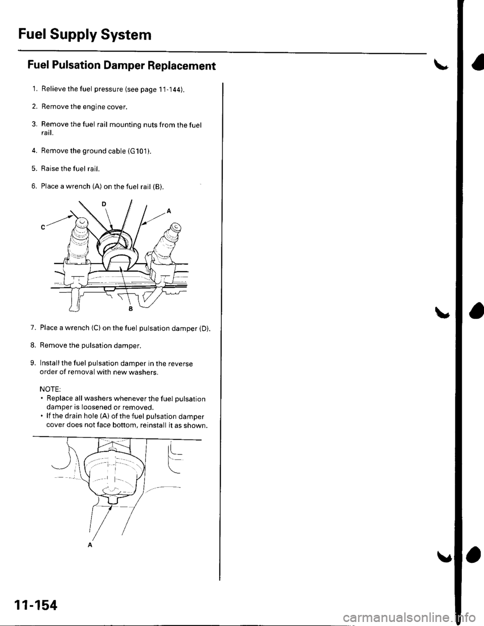
6. Place awrench (A) onthefuel rail (B).
7. Place a wrench (C) onthefuel pulsation damper (D).
8. Remove the pulsation damper.
9. Installthe fuel pulsation damper in lhe reverse
order of removal with new washers.
NOTE:. Replace all washers wheneve r the fuel pulsation
damper is loosened or removed,. lf the drain hole (A) ofthefuel pulsationdamper
cover does not face bottom, reinstall it as shown.
11-154
Page 362 of 1139
Fuel Tank Replacement
Relievethefuel pressure (see page 11-144).
Drain the fuel tank: Remove the fuel pump (see page 1 1-153). Using a hand pump, hose, and container suitable for
gasoline. draw the fuel from the fuel tank.
Jack up the vehicle, and suppon it with safety stands.
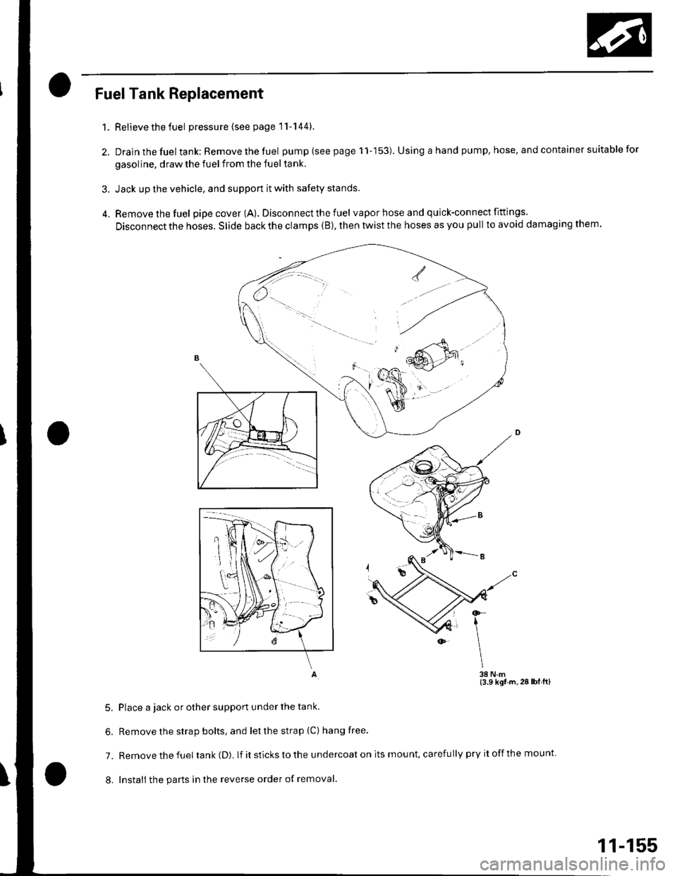
Remove the fuel pipe cover (A). Disconnect the fuel vapor hose and quick-connect fittings.
Disconnect the hoses. Slide back the clamps (B), then twist the hoses as you pull to avoid damaging them.
A 38 N.m(3.9 ksf.m,28lbfft)
5. Place a jack or other support under the tank.
6. Removethe strap bolts, and letthestrap (C) hangfree.
7. Remove the fuel tank (D). lf itstickstothe undercoaton its mount, carefully pry itoffthe mount
8. Install the parts in the reverse order of removal.
1.
2.
3.
(}
\
11-155
Page 363 of 1139
Fuel Supply System
Fuel Gauge Sending Unit Test
Special Tools Required
Fuel sender wrench 07XAA-001010A
NOTE; For the fuel gauge system circuit diagram, referto the Gauges Circuit Diagram (see page 22-58||.
1. Checkthe No. 10 fUETER {7.5A)fuse in the under-
dash fuse/relay box before testing.
2. Do the gauge drive circuit check (see page 22-56|l.
' lf the fuel gauge needle sweeps from minimuni
to maximum position and then returns to the
minimum position. the gauge is OK. Go to step 3.. lf the fuel gau ge need le does not sweep from
minimum to maximum position position and
then return to the minimum position, replace thegauge assembly and retest.
3. Turn the ignition switch OFF.
4. Remove the rear seat cushion {see page 20-80).
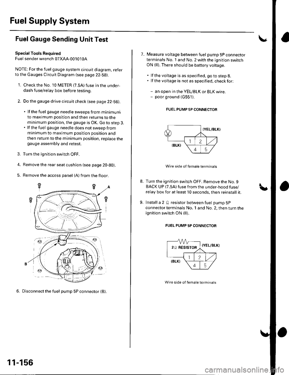
5. Remove the access panel (A)from the floor.
6. Disconnect the fuel pump 5P connector {B).
-ztr
11-156
7. Measure voltage between fuel pump 5P connectorterminals No. 1 and No. 2 with the ignition switchON (ll). There should be battery voltage.
. lf the voltage is as specified, go to step 8.. lf the voltage is notasspecified,checkfor:
- an open in the YEUBLK or BLK wire.- poor ground (G551).
FUEL PUMP 5P CONNECTOR
Wire side of female terminals
Turn the ignition switch OFF. Remove the No. 9BACK UP (7.5A)fuse from the under-hood fuse/
relay box for at least 10 seconds, lhen reinstall it.
Install a 2 Q resistor between fuel pump 5P
connector lerminals No. 1 and No. 2, then turn the
ignition switch ON (ll).
FUEL PUMP 5P CONNECTOR
-VVV-
29RESISTOR,
=-a
{Y
\
//,(elrt \
\45/
{YEL/BLK)
Wire side of female terminals
Page 364 of 1139
10. Checkthatthe pointerof thefuel gauge indicates"F".
. lf the pointer does not indicate "F", replace the
ga uge.. lf the pointer indicates "F", inspect the fuel
gauge sending unit.
NOTE: The pointer of the fuel gauge retu rns to the
bottom of the gauge dial when the ignition switch
is OFF, regardless of the fuel level. -
11. Relieve the fuel pressure (see page 11-144\.
12. Remove the fuelfill cap.
13. Disconnect the quick-connect fittings from the fuel
pump.
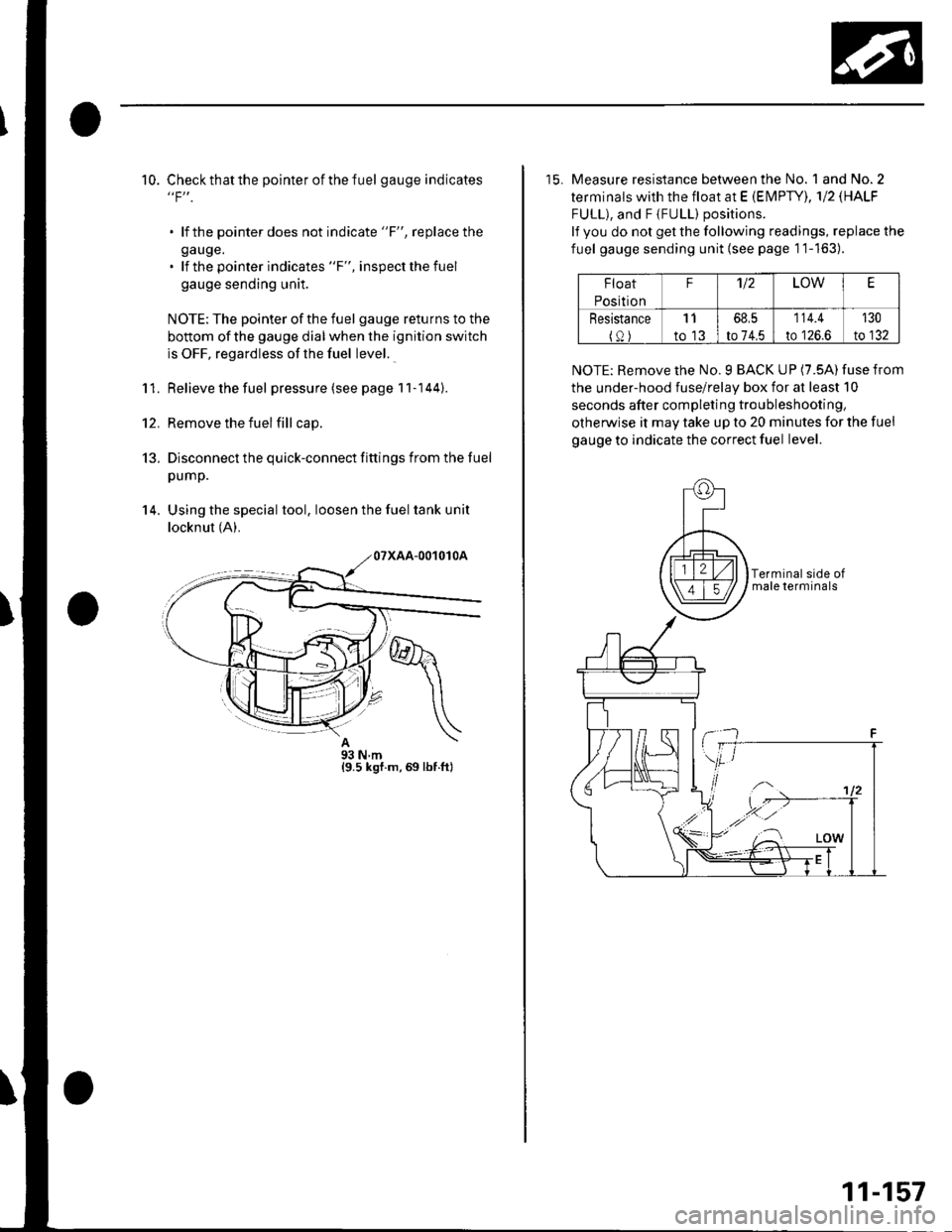
14. Using the special tool, loosen the fuel tank unit
locknut (A).
A93Nm{9.5 ksf.m,69 lbf.ft}
15. Measure resistance between the No. 1 and No.2
terminals with the float at E (EN4PTY), 'l12 \HALF
FULL), and F {FULL) positions.
lf you do not get the following readings, replace the
fuel gauge sending unit {see page 1'1-163).
Float
Position
F'U2LOWE
Resistance
{0)
11
to 13
68,5
to 74.5
114.4
to 126.6
130
to 132
NOTE: Remove the No. 9 BACK UP (7.5A) fuse from
the under-hood fuse/relay box for at least 10
seconds after completing troubleshooting,
otherwise it may take up to 20 minutes for the fuel
gauge to indicate the correct fuel level.
11-157
Page 365 of 1139
Fuel Supply System
1.
4,
Low Fuel Indicator Test
Do the fuel gauge sending unit test (see page 11,
rcol.
. lf the system is OK, go to step 2.. lf the system has any malfunction, repair it.
Turn the ignition switch OFF. Remove the No. 9
BACK UP (10A) fuse from the under-hood fuse/
relay box for at least 30 seconds, then reinstall it.
Turn the ignition switch ON (ll) with the float at the
E (EMPry) position.
. lf the low fuel indicator is on, go to step 4.. lf the low fuel indicator is not on, refer to the low
fuel indicator Circuit Diagram (see page 22-58)
and check the circuit.
Turn the ignition switch OFF. Remove the No. 9
BACK UP (10A) fuse from the under-hood fuse/
relay box for at least 30 seconds, then reinstall it.
Lift the float above the LOW position.
. lf the lowfuel indicatorgoes off,the system is OK.. lf the low fuel indicator is still on, refer to the low
fuel indicator Circuit Diagram {see page 22-58),
and check the circuit.
11-158
\,
Page 366 of 1139
Intake Air System
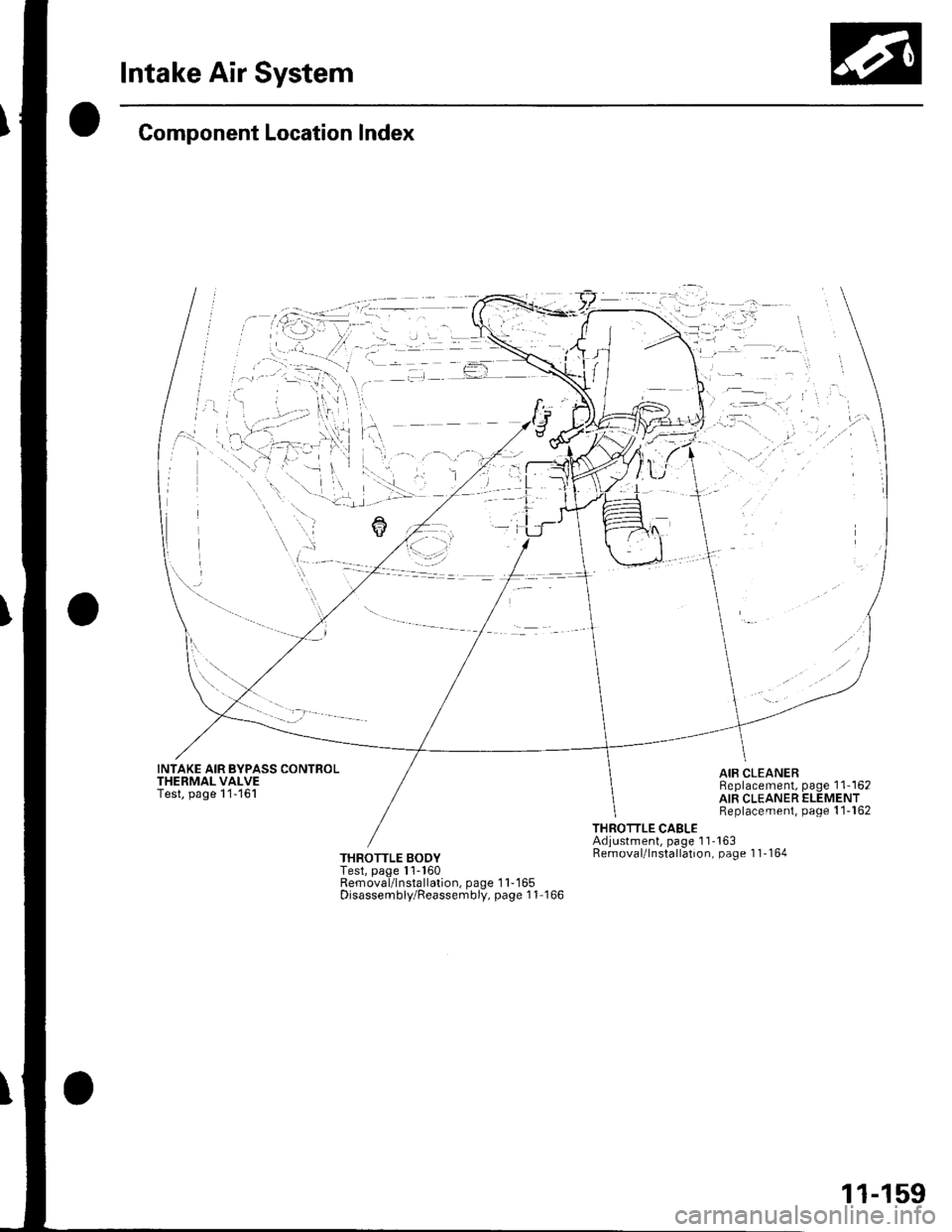
Component Location Index
INTAKE AIR BYPASS CONTROLTHERMAL VALVETest, page 1'1-161
i l.
AIR CLEANERReplacement, page 1 1'162AIR CLEANER ELEMENTReplacement, page 1 1-162
THROTTLE CABLEAdjustment, page 1 1-163Removal/lnstallation, page 1 1-164THROTTLE BODYTest, page l'l-160Removal/lnstallation, page 1 1-165Disassembly/Reassembly, page 1 1 166
11-159
Page 367 of 1139
Intake Air System
Throttle Body Test
NOTE:. Do not adjust the throttle stop screw. lt is preset at the
factory.. lf the malfunction indicator lamp (MlL) has been
reported on, check for diagnostic trouble codes(DLCS) (see page 11 3).
1. With the engine off, check the throttle cable
movement. The cable should move without binding
or sticking.
. lf lhe cable moves OK, goto step 2.. lf the cable binds or sticks, check it and its routing.. lf the cable isfaulty, reroute itor replace itand
adjust it (see page 11-163), then go to step 2.
2. l\4ove the throttle lever by hand to see if the throftle
valve and/or shaft are too loose or too tight.
. lf there is excessive play in the throttle valve
shaft, or any binding in the throttle valve at the
fully closed position, replace the throttle body.. lf thethrottlevalve and shaft are OK, goto step3.
3. Connect the scan toolto the DLC.
Turn the ignition switch ON (ll).
Check the throttle position with the scan tool. The
reading should be about 10% when the throttle is
fully closed and about 90% when the throttle is fully
openeo.
. lf the throttle position is correct, the throttle body
is OK.. lf thethrottle position is notcorrect, replace the
throttle body.
5.
11-160
!
Page 368 of 1139
Intake Air Bypass GontrolThermalValve Test
Special Tools Required
Vacuum Pump/Gauge,0 30 in. Hg A973X-041-XXXXX
1. Stan the engine. Then let it idl€.
NOTE: The engine coolant temperature must be
below 149'F (65'C).
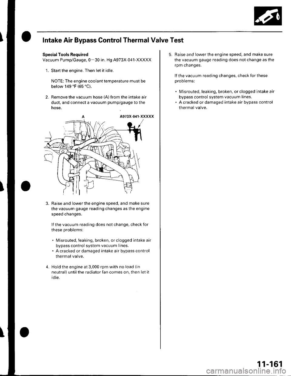
2. Remove the vacuum hose (A)from the intake air
duct, and connect a vacuum pump/gauge to the
nose.
3. Raise and lowerthe engine speed. and make sure
the vacuum gauge reading changes as the engine
speeo cnanges.
lf the vacuum reading does not change, check for
these problems:
. Misrouted, leaking, broken, or clogged intake air
bypass control system vacuum lines.. A cracked or damaged intake air bypass control
thermal valve.
4. Hold the engine at 3,000 rpm with no load (in
neutral) until the radiator fan comes on, then let it
id le.
5. Raise and lower the engine speed, and make sure
the vacuum gauge reading does not change as the
rpm cnanges.
lf the vacuum reading changes, check for these
proorems:
. l\4isrouted, leaking, broken, or clogged intake air
bypass control system vacuum lines.. A cracked or damaged intake air bypass control
thermal valve.
11-161
Page 369 of 1139
Intake Air System
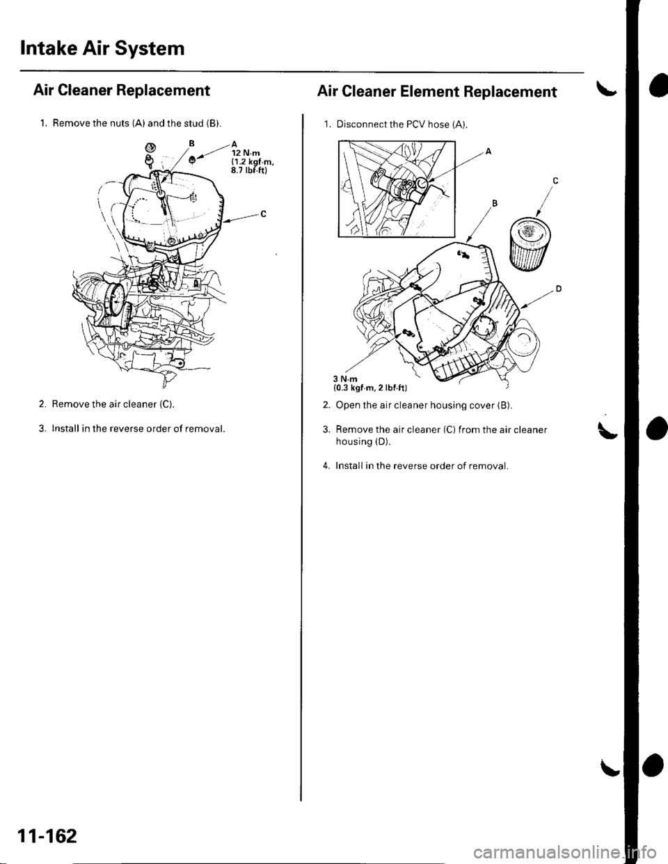
1. Remove the nuts (A) and the stud (B).
Air Cleaner Replacement
Remove the air cleaner (C).
Install in the reverse order of removal.
2.
3.
11-162
Air Cleaner Element Replacement
1. Disconnect the PCV hose 1A).
Open the air cleaner housing cover (B).
Remove the air cleaner (C) from the air cleaner
housing (D).
Install in the reverse order of removal.
2.
3.\,
4.
{0.3 kgf m,2lbf.ft)
Page 370 of 1139
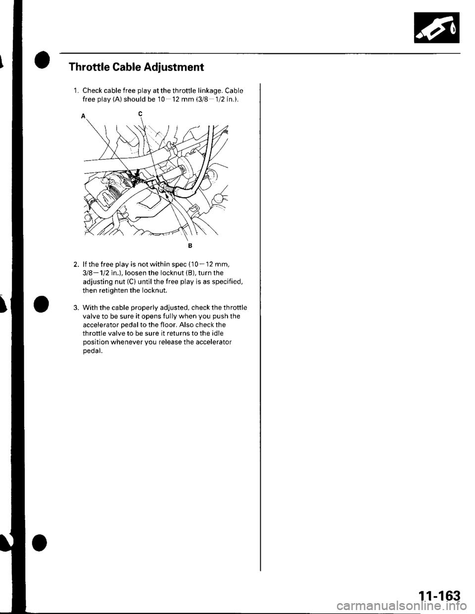
Throttle Cable Adjustment
1.Check cable free play at the throttle linkage. Cable
free pf av (A) should be 10 12 mm (3/8 1/2 in.).
lf the free play is not within spec (10 - 12 mm,
318-112ln.l,loosen the locknut (B), turn the
adjusting nut (C) untilthe free play is as specified,
then retighten the locknut.
With the cable properly adjusted, check the throttle
valve to be sure it opens fully when you push the
accelerator pedal to the floor. Also check the
throttle valve to be sure it returns to the idle
position whenever you release the accelerator
peoar.
11-163