idle control HONDA CIVIC 2003 7.G Owner's Guide
[x] Cancel search | Manufacturer: HONDA, Model Year: 2003, Model line: CIVIC, Model: HONDA CIVIC 2003 7.GPages: 1139, PDF Size: 28.19 MB
Page 558 of 1139
EPS Control Unit Removal/
Installation
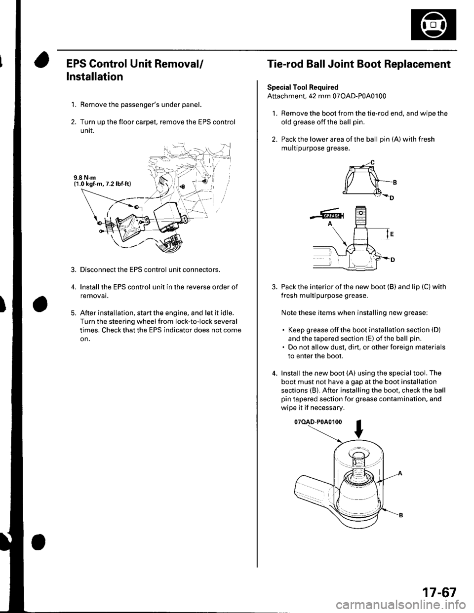
1. Remove the passenger's under panel.
2. Turn up the floor carpel, remove lhe EPS control
untr.
Disconnect the EPS control unit connectors.
lnstallthe EPS control unit in the reverse order of
removal.
After installation, start the engine, and let it idle.
Turn the steering wheelfrom lock-to-lock several
times. Check that the EPS indicator does not come
on.
3.
E
Tie-rod Ball Joint Boot Replacement
Special Tool Required
Attachment, 42 mm 07OAD-P0A0100
l. Remove the boot from the tie-rod end, and wipe the
old grease off the ball pin.
2. Pack the lower area of the ball pin(A)wilhfresh
mulr purpose grease.
3. Pack the interior of the new boot (B) and lip (C) with
fresh multipurpose grease.
Note these items when installing new grease;
. Keep grease offthe boot installation section (D)
and the tapered section (E) of the ball pin.
. Do not allow dust, dirt, or other foreign materials
to enter the boot.
4. Installthe new boot (A) using the specialtool. The
boot must not have a gap at the boot installation
sections (B). After installing the boot. check the ball
pin tapered section for grease contamination, and
wipe it if necessary.
07(lAD-P0A0100
*-4
r/ \-,d______i.l+_D
-6rA
17-67
Page 716 of 1139
Dashboard
Dashboard Center Panel Removal/lnstallation
NOTE:. Put on gloves to protect your hands.. When prying with a flat-tip screwdriver, wrap it with
protective tape, and apply protective tape around the
related parts, to prevent damage.. Take care not to scratch the dashboard and related
parts.
1. Make sure you have the anti-theft code for the radio,
the write down the frequencies for the preset
buttons.
Remove these items:
. Driver's dashboard lower cover (see page 20-59)
. Passenger's dashboard lower cover (see page
20-63).. Glove box (see page 20-63).. Shift lever trim {see page 20-61).
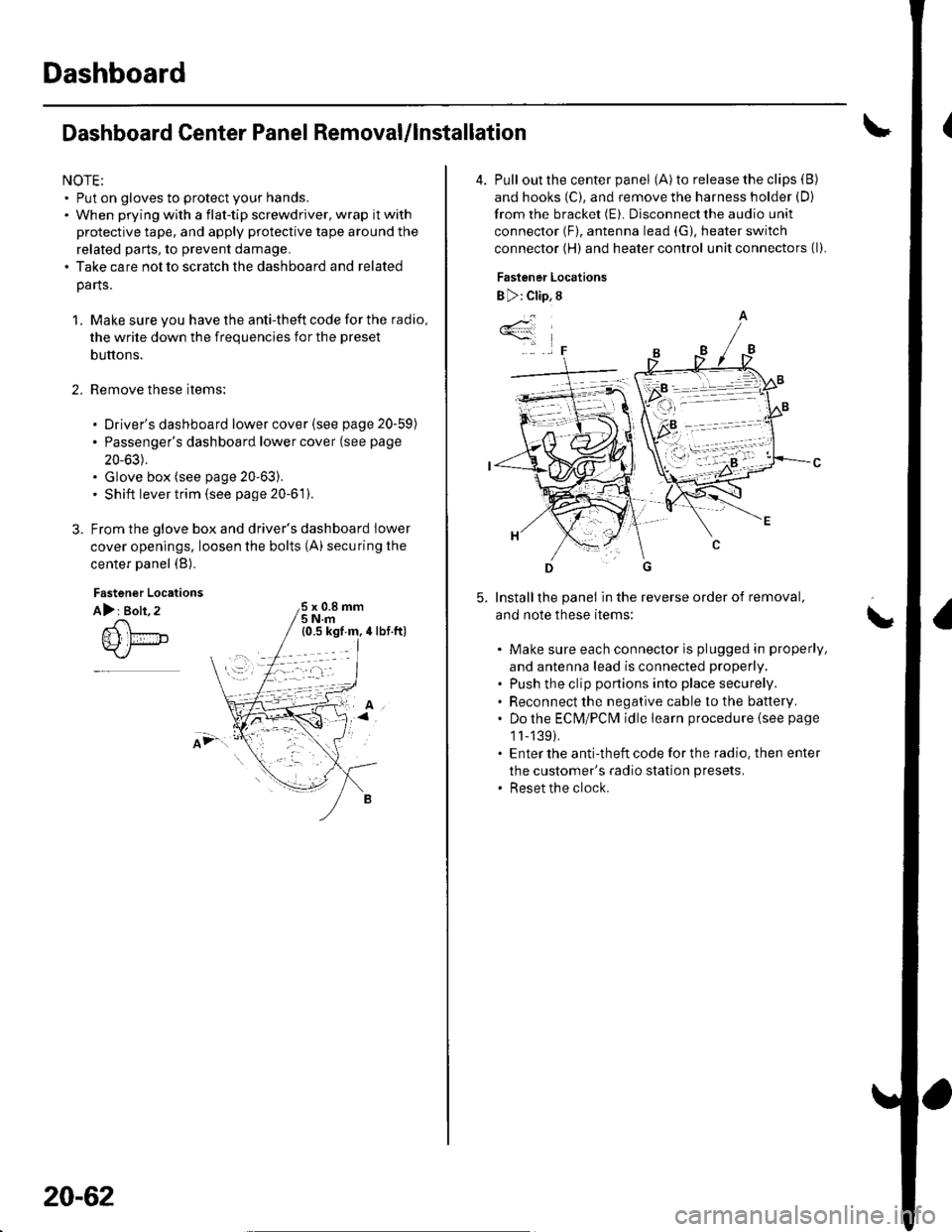
From the glove box and driver's dashboard Iower
cover openings, loosen the bolts (A) securing the
center panel (B).
2.
Fastener Locations
A): Bolt, 2x 0.8 mm5Nm
;.'
20-62
4. Pull out the center panel (A) to release the clips (B)
and hooks (C), and remove the harness holder (D)
from the bracket (E). Disconnect the audio unit
connector (F), antenna lead (G), heater switch
connector (H) and heater control unit connectors (l).
Fastener Locations
B ): Clip, 8
Installthe panel in the reverse order of removal,
and note these items:
Make sure each connector is plugged in properly,
and antenna lead is connected properly.
Push the clip portions into place securely.
Reconnect the negative cable to the battery.
Do the ECN4/PCt\4 idle learn procedure {see page
1l-139).
Enter the anti-theft code for the radio. then enter
the customer's radio station presets.
Reset the clock.
*4
,F
\
Page 722 of 1139
Dashboard
Dashboard Removal/lnstallation
(cont'd)
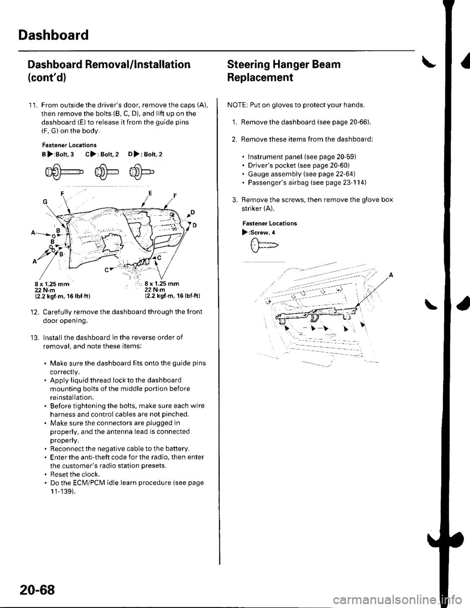
11. From outside the driver's door, remove the caps (A),
then remove the bolts (8, C, D), and lift up on the
dashboard (E) to release it from the guide pins
(F. G) on the body.
Fastener Locations
B>rBolt.3 C>: Bolt,2 D>: Bolt,2
m6[-,,,,",",,-,F6't---'' ffi'!--v{/- Kr* w-
B
$7:
^/761:
/,-,. r:; 8 x 1.25 mm22Nm(2.2 kgf.m, 16lbf.ft)
13.
{2.2 kgf m, 16lbf.ftl
Carefully remove the dashboard through the front
door opening.
lnstall the dashboard in the reverse order of
removal, and note these items:
. Make sure the dashboard fits onto the guide pins
correctly.. Apply liquid thread lock to the dashboard
mounting bolts of the middle portion before
reinstallation.. Before tightening the bolts, make sure each wire
harness and control cables are not pinched.
. Make sure the connectors are plugged in
properly, and the antenna lead is connected
propeny.. Reconnect the negative cable to the battery.. Enter the anti-theft code for the radio, then enter
the customer's radio station presets.
. Reset the clock.. Do the ECM/PCM idle learn procedure isee page
1 '1-139).
20-68
Steering Hanger Beam
Replacement
NOTE: Put on gloves to protect your hands.
1, Remove the dashboard (see page 20-66).
2. Remove these items from the dashboard:
. lnstrument panel (see page 20-59). Driver's pocket (see page 20-60). Gauge assembly (see page 22-64). Passenger's airbag (see page 23-'l 14)
Remove the screws, then remove the glove box
striker (A).
Fastenea Locations
):Screw,4
\
Page 811 of 1139
Heating and Air Gonditioning
Blower Unit Removal and Installation {cont'd}
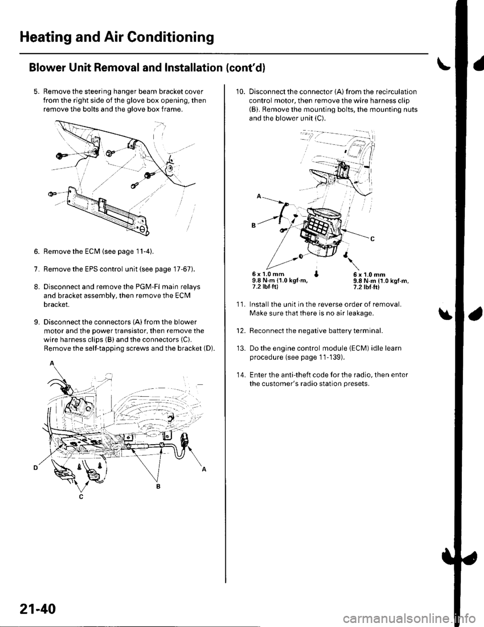
Remove the steering hanger beam bracket cover
from the right side of the glove box opening, then
remove the bolts and the olove box frame.
1.
8.
9.
Remove the ECM (see page 11-4).
Remove the EPS control unit (see page 17-67).
Disconnect and remove the PGM-Fl main relays
and bracket assembly, then remove the ECM
bracket.
Disconnect the connectors {A) from the blower
motor and the power transistor, then remove the
wire harness clips (B) and the connectors (C).
Remove the self-tapping screws and the bracket (D).
A
21-40
10. Disconnectthe connector {A) from the recirculation
control motor, then remove the wire harness clip
{B). Remove the mounting bolts, the mounting nuts
and the blower unit (C).
6x 1.0 mm I9.8 N.m (1.0 kgt.m,7.2 tbt.ftl
6x1.0mm9.8 N.m (1.0 kgf.m,?.2 tbf.ft)
11.
14.
Installlhe unit in the reverse order of removal.
Make sure that there is no air leakage.
Reconnect the negative battery terminal.
Do the engine control module (ECM) idle learn
procedure {see page 11-139).
Enter the anti-theft code for the radio, then enter
the customer's radio station presets.
\
'13.
Page 816 of 1139
13. Installthe heater core and the evaporator core in
the reverse order of removal.
14. Installthe heater unit in the reverse order of
removal, and note these items:
. Do not interchange the inlet and outlet heater
hoses, and installthe hose clamps securely.. Refillthe cooling system with engine coolant (see
page 10-6).. Adjust the heater valve cable (see page 2'l-461.. Make sure that there is no coolant leakage.. Make sure that there is no air leakage.. Refer to evaporator core replacement {see step 6
on page 21-42).. Do the engine control module (ECl\4) idle learn
procedure (see page 11-139).. Enter the anti-theft code for the radio, then enter
the customer's radio station Dresets.
21-45
Page 818 of 1139
Compressor Replacement
1. lf the compressor is marginally operable, run the
engine at idle speed, and let the air conditioning
work for a few minutes, then shut the engine off.
2. Make sure you have the anti-theft code for the radio,
then write down the frequencies for the radio's
preset buttons.
3. Disconnect the negative cable from the battery.
4. Recover the refrigerant with a recovery/recycling/
charging station (see page 21-53).
5. Remove the alternator (see page 4-29).
6. Remove the Ay'C condenser fan assembly (see page
10-10).
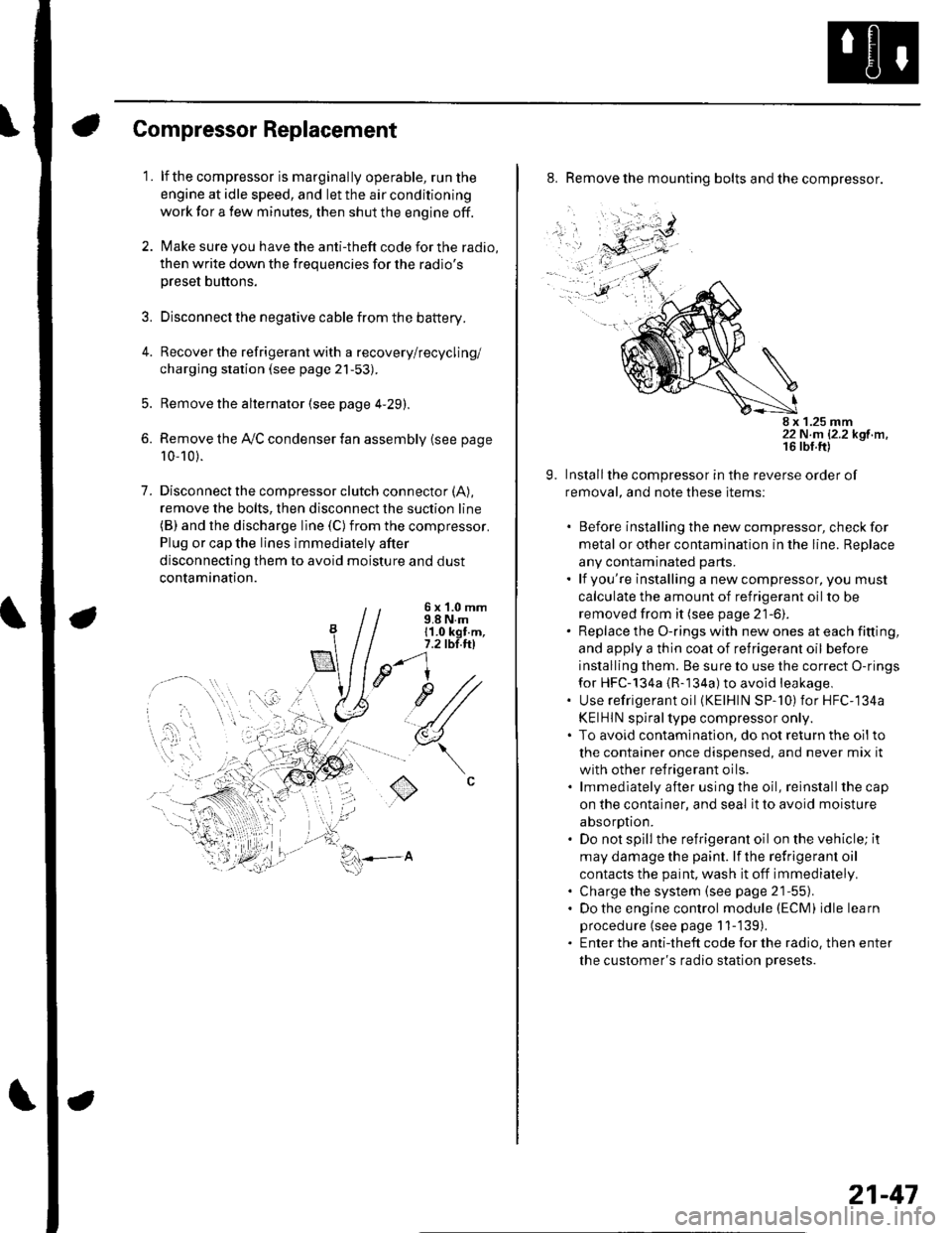
7. Disconnectthe compressor clutch connector (A),
remove the bolts, then disconnect the suction line(B) and the discharge line (C)from the compressor.
Plug or cap the lines immediately after
disconnecting them to avoid moisture and dust
contamination.
6 x '1.0 mm9.8 N.m11.0 kgt.m,7.2 tbl.ttl
u1/
(
o
8. Remove the mounting bolts and the compressor.
8 x 1.25 mm22 N.m 12.2 kgf.m.
9. Installthe compressor in the reverse order of
removal, and note these items:
. Before installing the new compressor, check for
metal or other contamination in the line. Replace
any contaminated parts.. lf you're installing a newcompressor, you must
calculate the amount of refrigerant oil to be
removed from it (see page 21-6).. Replace the O-rings with new ones at each fitting,
and apply a thin coat of refrigerant oil before
installing them. Be sure to use the correct O-rings
for HFC-134a {R-134a) to avoid leakage,. Use refrigerant oil (KElHlN SP-'10) for HFC-134a
KEIHIN spiral type compressor only.. To avoid contaminatlon, do not return the oilto
the container once dispensed, and never mix it
with other refrigerant oils.. lmmediately after using the oil, reinstallthe cap
on the container, and seal it to avoid moisture
absorption.. Do not spill the refrigerant oil on the vehicle; it
may damage the paint. lf the refrlgerant oil
contacts the paint, wash it off immediately.. Charge the system (see page 21-55).. Do the engine control module (ECM) idle learn
procedure (see page 11-'139).. Enter the antitheft code for the radio, then enter
the customer's radio station presets.
21-47
Page 876 of 1139
Under-dash Fuse/Relay Box
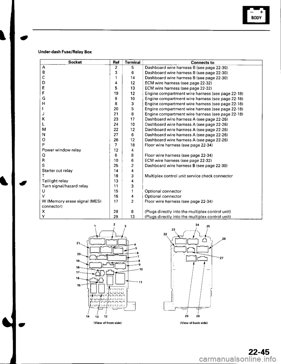
SocketRefTerminal Connects to
B
c
D
E
F
G
H
J
K
M
N
o
P
Power window relay
o
R
S
Starter cut relay
T
Taillight relay
Turn signal/hazard relay
U
W (Memory erase signal (MES)
connector)
X
Y
2
3
1
5
19
9
I
20
24
22
27
26
7
6
10
25
14
18
11
l5
to
17
28
5
6
14
13
12
10
3
:
11'10
1:
.o^
;;
4
8
2
i
nl
al
lt
2
Dashboard wire harness B {see page 22-30)
Dashboard wire harness B {see page 22-30)
Dashboard wire harness B (see page 22-30)
ECM wire harness (see page 22-32)
ECI\4 wire harness (see page 22-32)
Engine compartment wire harness (see page 22-'l8l
Engine compartment wire harness (se e page 22-181
Engine compartment wire harness (see page 22-18)
Engine compartment wire harness (se e page 22-18)
Engine compartment wire harness (see page 22-18)
Dashboard wire harness A (see page 22-26)
Dashboard wire harness A (see page 22-26)
Dashboard wire harness A (see page 22-26)
Dashboard wire harness A (see page 22-26)
Dashboard wire harness A (see page 22-26)
Floor wire harness (see page 22-34)
Floor wire harness (see page 22-34)
ECM wire harness (see page 22-32)
Dashboard wire harness B (see page 22-30)
Multiplex control unit service check connector
Optional connector
Optional connector
Floor wire harness (see page 22-34)
{Plugs directly into the multiplex control(Pluqs directlv into the multiDlex control
unat)
unrl)
I
13
tn--rlI U LI L.] L.Jh--n-UL]L]UL]
I] L] L] LI L]
!3 12
22-45
Page 877 of 1139
Power Distribution
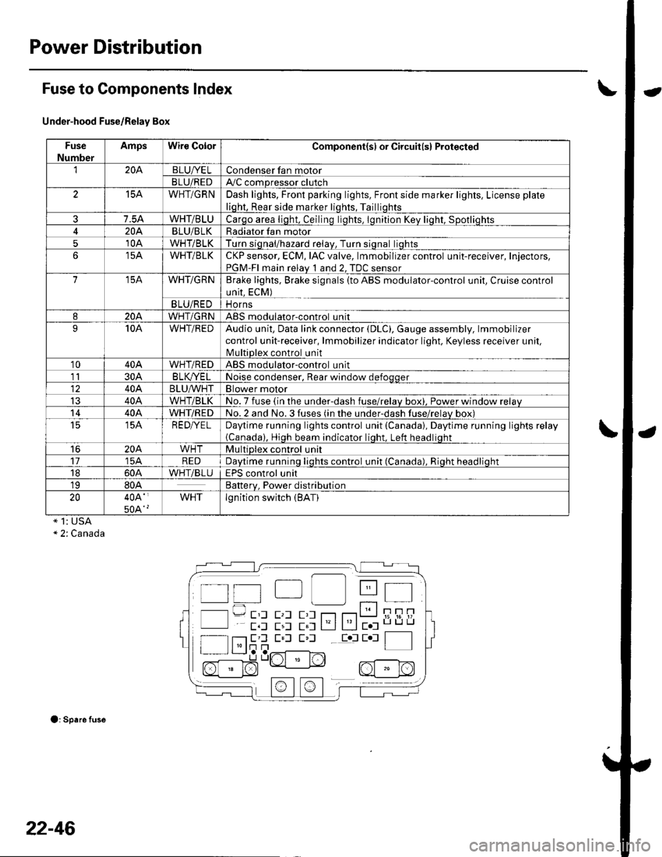
Fuse to Components lndex
Under-hood Fuse/Relay Box
Fuse
Number
AmpsWire ColorComponent(sl or Circuit(s) Protected
'I204BLUI/ELCondenser fan motor
BLU/REDAy'C compressor clutch
15AWHT/GRNDash lights, Front parking lights, Front side marker lights, License plate
liqht, Rear side marker liqhts, Tailliqhts
7.5AWHT/BLUCarqo area liqht, Ceilinq liqhts. lqnition Kev liqht. Sootliohts
204BLU/BLKRadiator fan motor
510AWHT/BLKTurn siqnal/hazard relav, Turn siqnal liqhts
15AWHT/BLKCKP sensor, ECM, IAC valve, lmmobilizer control unit-receiver, Injectors,
PGM-FI main relav 1 and 2. TDC sensor
715AWHT/GRNBrake lights, Brake signals (to ABS modulator-control unit, Cruise control
unit, ECM)
BLU/REDi1 Orns
820AWHT/GRNABS modulatorcontrol unit
910AWHT/REDAudio unit, Data link connector (DLC), Gauge assembly, lmmobilizer
control unit-receiver, lmmobilizer indicator light. Keyless receiver unil,
lvlultiDlex control unit
1040AWHT/REDABS modulator-control unit
1130AB LK/YE LNoise condenser, Rear window defoqqer
40ABLU^^/HTBlower motor
IJ40AWHT/BLKNo. 7 fuse (in the under-dash fuse/relav box), Power window relav
1440AWHT/REDNo.2 and No.3 fuses (in the under-dash fuse/relav box)
t515AREDI/ELDaytime running lights control unit (Canada), Daytime running lights relay
{Canada), Hioh beam indicator liqht. Left headliqht
16204WHTMultiplex control unit
1715AREDDavtime runninq liqhts control unit (Canada). Rioht headlioht
1860AWHTiBLUEPS control unit
1980ABatterv. Power distribution
2040A'
50A'?
WHTlgnition switch (BAT)
* 1: USA" 2. Canada
O: Spare fuse
t t"| lll Itt 4t I
l l---- E'l E,l E,l r--r r---r t__J i; i6'!/'
E,l E,l E,l Eol E l f__--lI l'lr]n | |I r L__J,a ,..r^{-------l^-,
n[:]$"Lrt " N2, nf - r^l
22-46
Page 880 of 1139
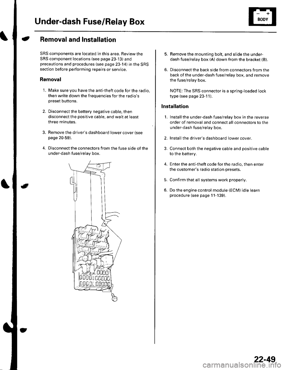
Under-dash Fuse/Relay Box
Removal and Installation
SRS components are located in this area. Review the
SRS component locations {see page 23-13) andprecautions and procedures (see page 23-14) in the SRS
section before performing repairs or service.
Removal
1. Make sure you have the anti-theft code for the radio,
then write down the frequencies for the radio's
preset buttons.
2. Disconnectthe battery negative cable, then
disconnect the positive cable, and wait at least
three minutes.
3. Remove the driver's dashboard lower cover (see
page 20-59).
4. Disconnect the connectors from the fuse side of the
under-dash fuse/relay box.
5. Remove the mounting bolt, and slide the under-
dash fuse/relay box (A) down from the bracket {B).
6. Disconnect the back side from connectors from the
back of the under-dash fuse/relay box, and remove
the fuse/relay box.
NOTE:The SRS connector is a spring-loaded lock
type (see page 23-1 1).
lnstallation
1. Installthe under-dash fuse/relay box in the reverse
order of removal and connect all connectors to the
under-dash fuse/relay box.
2. Installthe driver's dashboard lower cover.
3. Connect both the negative cable and positive cable
to the battery.
4. Enter the anti-theft code for the radio, then enter
the customer's radio station presets.
5. Confirm that all systems work properly,
6. Do the engine control module (ECM) idle learn
procedure (see page 11-139).
22-49
Page 888 of 1139
\
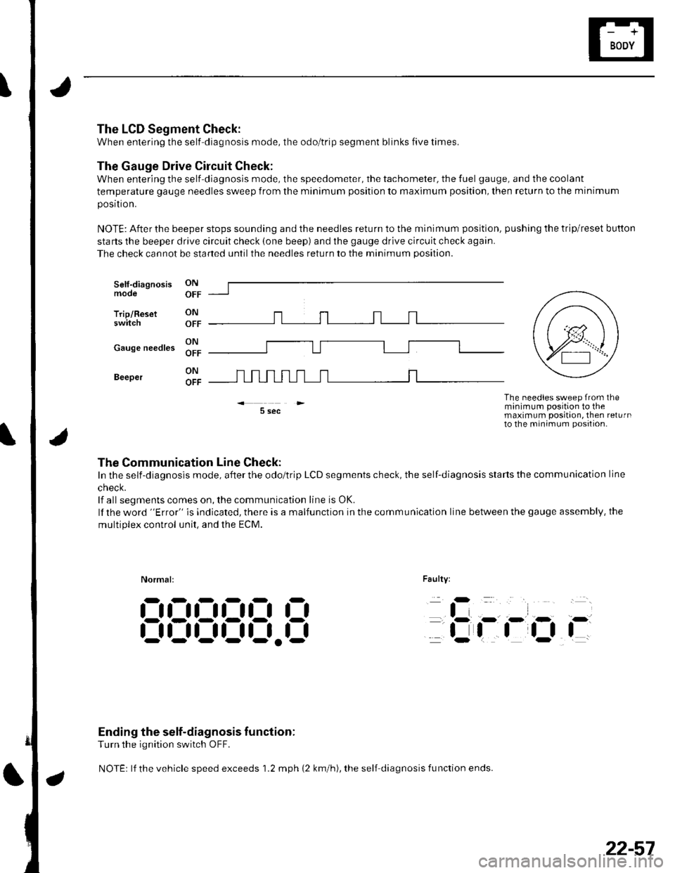
The LCD Segment Check:
When entering the self-diagnosis mode, the odo/trip segment blinks five times.
The Gauge Drive Circuit Check:
When entering the self-diagnosis mode, the speedometer, the tachometer, the fuel gauge, and the coolant
temperature gauge needles sweep from the minimum position to maximum position, then return to the minimum
posrtron.
NOTE: After the beeper stops sounding and the needles return to the minimum position, pushing the trip/reset button
starts the beeper drive circuit check (one beep) and the gauge drive circuit check again.
The check cannot be started untilthe needles return to the minimum position.
Self-diagnosismode
Trip/Resetswitch
ON
OFF
ON r-r r-r r-r .-1 r-r r-r
;; lll u u l_l L__l I l-l
5 sec
Faulty:
The needles sweep from theminimum position to themaximum position, then returnto the minimum position-
Normal:
iD
tli-
flOi-
Ending the self-diagnosis function:
Turn the ignition switch OFF.
NOTEr lf the vehicle speed exceeds 1.2 mph {2 km/h), the self diagnosis fu nction ends.
:-l!:!!JlJ!J
,-
t,-- - ,- r- i-
| | | ttfi- r-
9l- r n =--llJL--oFF _---
cause needles Xl" f---U---------l [-----l
Beeper
The Communication Line Check:
In the self-diagnosis mode, after the odo/trip LCD segments check, the self-diagnosis starts the communication line
cnecK.
lf all segments comes on, the communication line is OK.
lf the word "Error" is indicated, there is a malfunction in the communication line between the gauge assembly. the
multiDlex control unit. and the ECM.
@,
22-57