HONDA CIVIC 2003 7.G Workshop Manual
Manufacturer: HONDA, Model Year: 2003, Model line: CIVIC, Model: HONDA CIVIC 2003 7.GPages: 1139, PDF Size: 28.19 MB
Page 661 of 1139
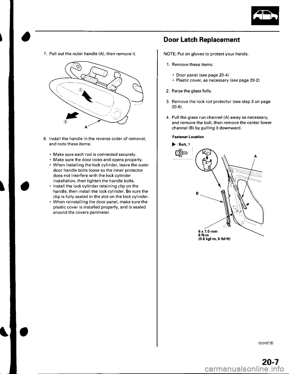
7. Pull out the outer handle (A), then remove it.
Installthe handle in the reverse order of removal,
and note these items:
. Make sure each rod is connected securelv.. Make sure the door locks and opens properly.. When installing the lock cylinder. leavetheouter
door handle bolts loose so the inner protector
does not interfere with the lock cylinder
installation, then tighten the handle bolts.. Install the lock cylinder retaining clip on the
handle, then install the lock cylinder. Be sure the
clip is fully seated in the slot on the lock cylinder.. When reinstalling the door panel, make sure the
plastic cover is installed properly, and is sealed
around the covers Derimeter.
Door Latch Replacement
NOTE: Put on gloves to protect your hands.
1. Remove these items:
3.
4.
. Door panel (see page 20-4). Plastic cover, as necessary (see page 20-2)
Raise the glass fully.
Remove the lock rod protector (see step 3 on page
20-6).
Pullthe glass run channel (A) away as necessary,
and remove the bolt, then remove the center lower
channel (B) by pulling il downward
Fastenor Location
> : Bolt, 1
IIilE
q
6x1.0mm8 N.m{0.8 kgf.m, 6 lbf.ftl
(cont'd)
20-7
Page 662 of 1139
Doors
Door Latch Replacement (cont'dl
5.
6.
7.
Disconnect the cylinder rod (see step 4 on page 20-
6).
Disconnect the outer handle rod (see step 5 onpage 20-6).
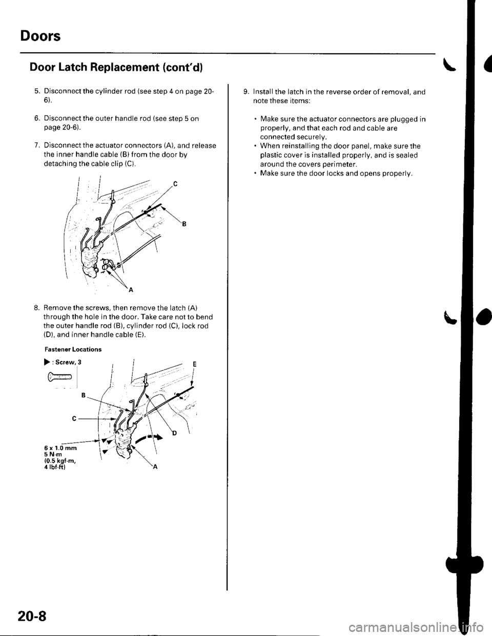
Disconnect the actuator connectors (A), and release
the inner handle cable (B)from the door by
detaching the cable clip (Ci.
Remove the screws, then remove the latch {A)
through the hole in the door. Take care not to bend
the outer handle rod (B), cylinder rod (C), lock rod(D), and inner handle cable (E).
Fastener Locations
8.
) : Screw
U.#
6x1.0mm5Nm{0.5 kgf.m,4 tbf.ft)
20-8
9. Installthe latch in the reverse order of removal, and
note these rtems:
. [Vlake sure the actuator conneclors are plugged in
properly, and that each rod and cable are
connected securely.. When reinstalling the door panel, make sure the
plastic cover is installed properly, and is sealed
around the covers perimeter.. Make sure the door locks and opens properly.
Page 663 of 1139
Door Glass and Regulator Replacement
NOTE: Put on gloves to protect your hands.
1. Remove these items:
. Door panel (see page 20-4). Plastic cover. as necessary (see page 20-2)
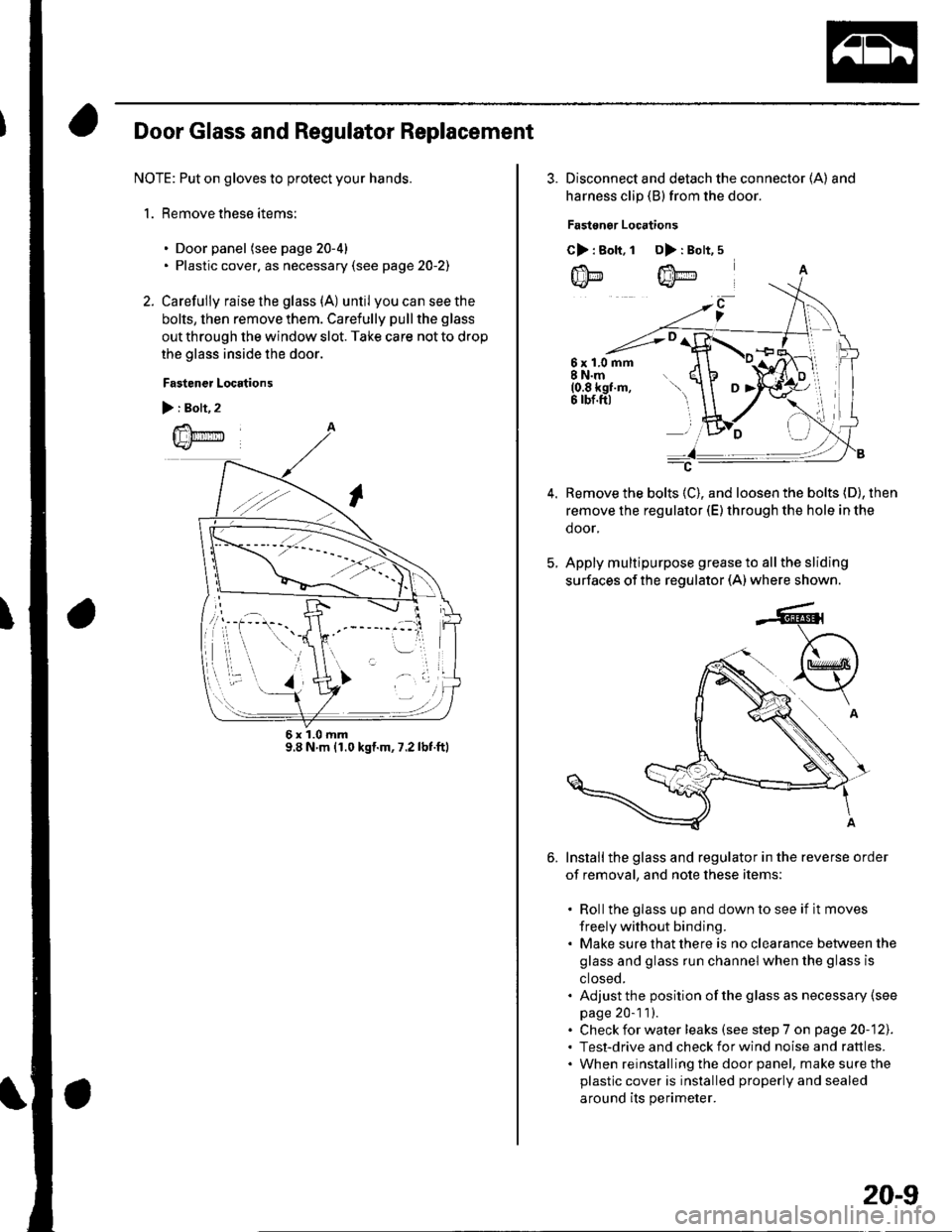
2. Carefully raise the glass (A) until youcanseethe
bolts, then remove them. Carefully pull the glass
out through the window slot. Take care not to drop
the glass inside the door.
Fastener Locations
):Boh,2
@
6x1.0mm9.8 N m {1.0 kgl.m, 7.2 lbf.ftl
3. Disconnect and detach the connector (A) and
harness clip (B) from the door.
Fastonor Locations
C>: Bolt.1 D>: Bolt,5
6x1.0mm8 N.m(0.8 kgf.m,6 rbf.ftl
Remove the bolts (C), and loosen the bolts (D), then
remove the regulator (E) through the hole in the
door,
Apply multipurpose grease to all the sliding
surfaces of the regulator (A) where shown.
Installthe glass and regulator in the reverse order
of removal, and note these items:
. Rollthe glass up and down to see if it moves
freely without binding.. Make sure that there is no clearance between the
glass and glass run channel when the glass is
ctoseo.. Adjust the position of the glass as necessary (see
page 20-1 1).. Check for water leaks (see step 7 on page 20-121.. Test-drive and check for wind noise and rattles.. When reinstalling the door panel, make sure the
plastic cover is installed properly and sealed
around its perimeter.
20-9
Page 664 of 1139
Doors
IDoor Sash Trim Replacement
NOTE: Take care not to scratch the door.
1. Remove the door glass outer weatherstrip.
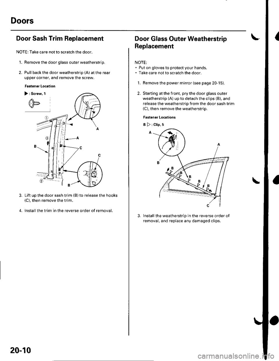
2. Pull back the door weatherstrip (A) at the rear
upper corner, and remove the screw.
Fasten6r Location
) : Screw, I
Lift up the door sash trim {B) to release the hooks(C), then remove the trim.
lnstallthe trim in the reverse order of removal.
3.
20-10
Door Glass Outer Weatherstrip
Replacement
NOTE:. Put on gloves to protect your hands.. Take care not to scratch the door
1. Remove the power mirror (see page 20-15).
2. Starting at the front, pry the door glass outer
weatherstrip (A) up to detach the clips (B), and
release the weatherstrip from the door sash trim(C), then remove the weatherstrip.
Fastener Locations
Install the weatherstrip in the reverse order ot
removal, and replace any damaged clips.
3.
B>:Clip,s
Page 665 of 1139
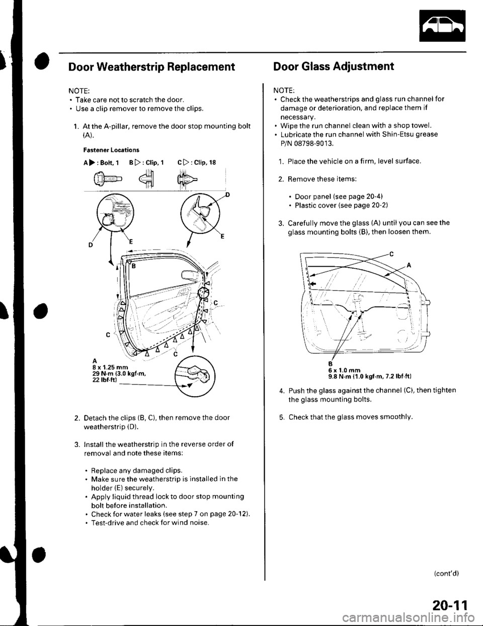
Door Weatherstrip Replacement
NOTE:. Take care not to scratch the door.. Use a clip remover to remove the clips.
1. At the A-pillar, remove the door stop mounting bolt
(A).
Fastener Locations
A>:Bott, 1 B>:Clip,1 C>:Clip, 18
Detach the clips (8, C), then remove the door
weatherstrip (D).
Install the weatherstrip in the reverse order of
removal and note these items:
. Replace any damaged clips.. Make sure the weatherstrip is installed ln the
holder (E) securely.. Apply liquid thread lock to door stop mounting
bolt before installation.. Check for water leaks (see step 7 on page 20-'121.. Test-drive and check for wind noase.
14.----'
'
'r, .,'o-,,tL' .
.rrt
Door Glass Adjustment
NOTE:. Check the weatherstrips and glass run channelfor
damage or deterioration, and replace them if
necessary.. Wipe the run channel clean with a shop towel.. Lubricate the run channel with Shin-Etsu grease
P/N 08798-9013.
1. Place the vehicle on a firm, level surface.
2. Remove these items:
. Door panel (see page 20-4). Plastic cover {see page 20'2)
3. Carefully move the glass (A) until you can see the
glass mounting bolts (B), then loosen them.
B6x1.0mm9.8 N.m (1.0 kgf.m, 7.2lbf.ft)
Push the glass against the channel (C), then tighten
the glass mounting bolts.
Check that the glass moves smoothly.
(cont'd)
20-11
Page 666 of 1139
Doors
Door Glass Adiustment {cont'd)
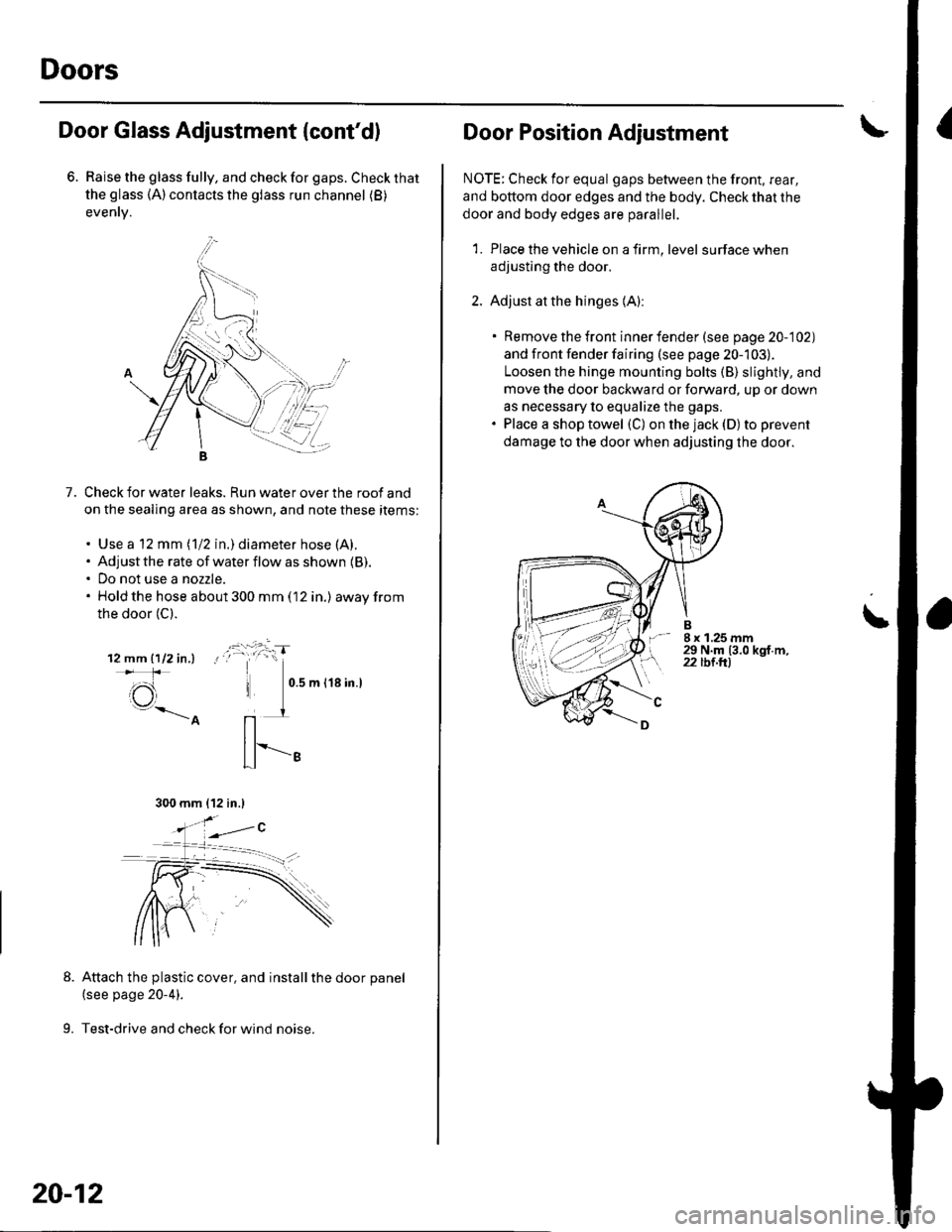
6. Raise the glass fully, and check for gaps. Check that
the glass (A) contacts the glass run channel (B)
evenrv.
7.Check for water leaks. Run water over the roof and
on the sealing area as shown, and note these items:
. Use a 12 mm (1/2 in.) diameter hose (A).. Adjust the rate of water flow as shown {B).. Do not use a nozzle.. Hold the hose about 300 mm (12 in.) awayfrom
the door (C).
12mm1112in,l !
\e
Attach the plastic cover, and installthe door panel(see page 20-4).
9. Test-drive and check for wind noise.
300 mm {12 in.l
20-12
Door Position Adiustment\
NOTE; Check for equal gaps between the front, rear,
and bottom door edges and the body. Check that the
door and body edges are parallel.
1. Place the vehicle on a firm, level surface when
adjusting the door.
2. Adjust at the hinges {A):
. Remove the front inner fender (see page 20-102)
and front fender fairing (see page 20-103).
Loosen the hinge mounting bolts (B) slightly, and
move the door backward or forward, uD or down
as necessary to equalize the gaps.. Place a shop towel (C) on the jack (D) to prevent
damage to the door when adjusting the door.
t, 8x1.25mm29 N.m (3.0 kgf.m,22 tbt.trl
\
Page 667 of 1139
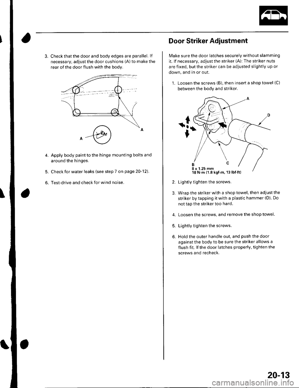
3. Check that the door and body edges are parallel. lf
necessary, adjust the door cushions (A) to make the
rear of the door flush with the bodv.
Apply body paint to the hinge mounting bolts and
around the hinges.
Check for water leaks (see step 7 on page 20-12).
Test-drive and check for wind noise.
5.
Door Striker Adjustment
Make sure the door latches securely without slamming
it. lf necessary, adjust the striker (A): The striker nuts
are fixed, but the striker can be adjusted slightly up or
down, and in or out.
1. Loosen the screws (B), rhen insert a shop towel (C)
between the body and striker.
Lightly tlghten the screws.
Wrap the striker with a shop towel, then adjust the
striker by tapping it with a plastic hammer (D). Do
not tap the striker too hard.
Loosen the screws, and remove the shop towel.
Lightly tighten the screws.
Hold the outer handle out, and push the door
against the body to be sure the striker allows a
flush fit, lf the door latches properly, tighten the
screws and recheck.
5.
6.
8 x 1.25 mm18 N.m 11.8 kgf m, 13 lbf.ft)
20-13
Page 668 of 1139
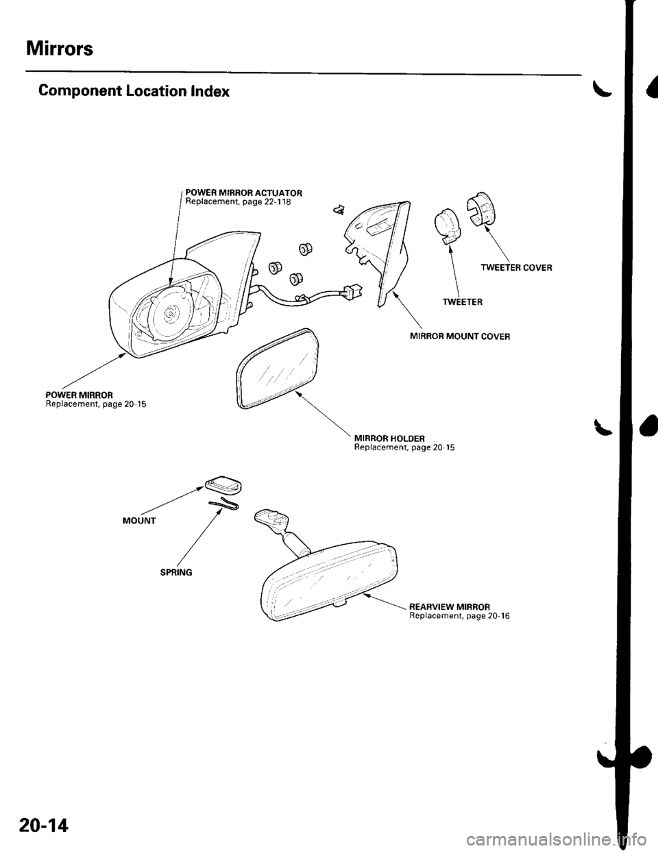
Mirrors
Component Location Index
POWER MIRRORReplacement, page 20-15
.a b\.\| \-r<,,/
\.J \\.4 \
1\
TWEETER
TWEETER
MIRROR MOUNT COVER
MIRROR HOLDERReplacement, page 20 '15
__.Q
-'-'MOUNT
/
/
REARVIEW MIRRORReplacement, page 20 16
POWER MIRROR ACTUATORReplacement, page 22-1'18
20-14
Page 669 of 1139
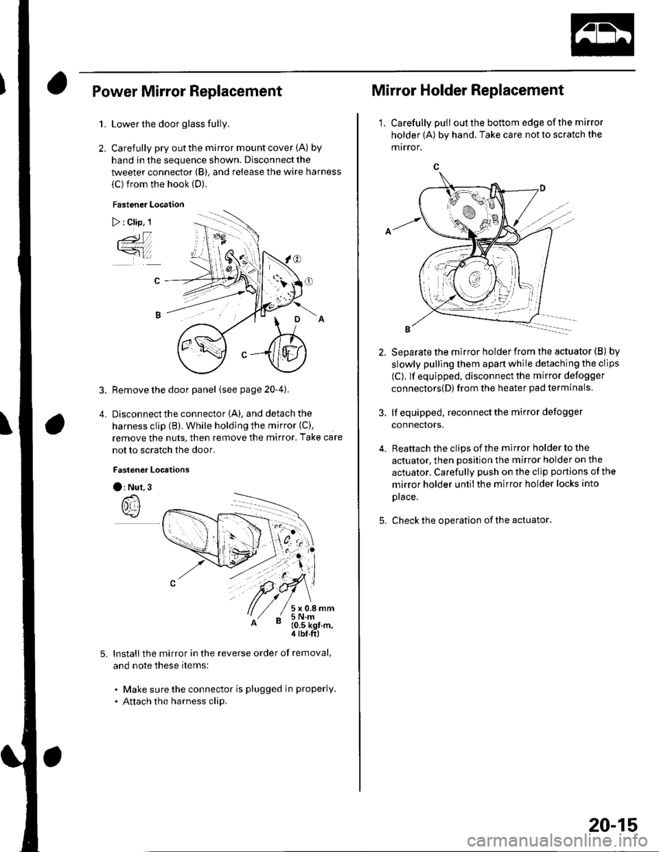
Power Mirror Replacement
1.
2.
5.
Lower the door glass fully.
Carefully pry out the mirror mount cover (A) by
hand in the sequence shown. Disconnect the
tweeter connector (B), and release the wire harness
(C) from the hook (D).
Fastener Location
) : Clip, 1
3. Remove the door panel (seepage20-4).
4. Disconnectthe connector (A), and detach the
harness clip (B). While holding the mirror {C),
remove the nuts, then remove the mirror. Take care
not to scratch the door.
Fastener Locrtions
O: Nut.3
lnstall the mirror in the reverse order of removal,
and note these items:
. Make sure the connector is plugged in properly.
. Attach the harness clip.
Mirror Holder Replacement
1. Carefully pulloutthe bottom edge ofthe mirror
holder (A) by hand. Take care not to scratch the
mrrror.
5.
Separate the mirror holder from the actuator (B) by
slowly pulling them apart while detaching the clips
(C). lf equipped, disconnect the mirror defogger
connectors{D) from the heater pad terminals.
lf equipped, reconnect the mirror defogger
connectors.
Reattach the clips of the mirror holder to the
actuator, then position the mirror holder on the
actuator. Carefully push on the clip portions of the
mirror holder untilthe mirror holder locks into
prace.
Check the operation of the actuator
20-15
Page 670 of 1139
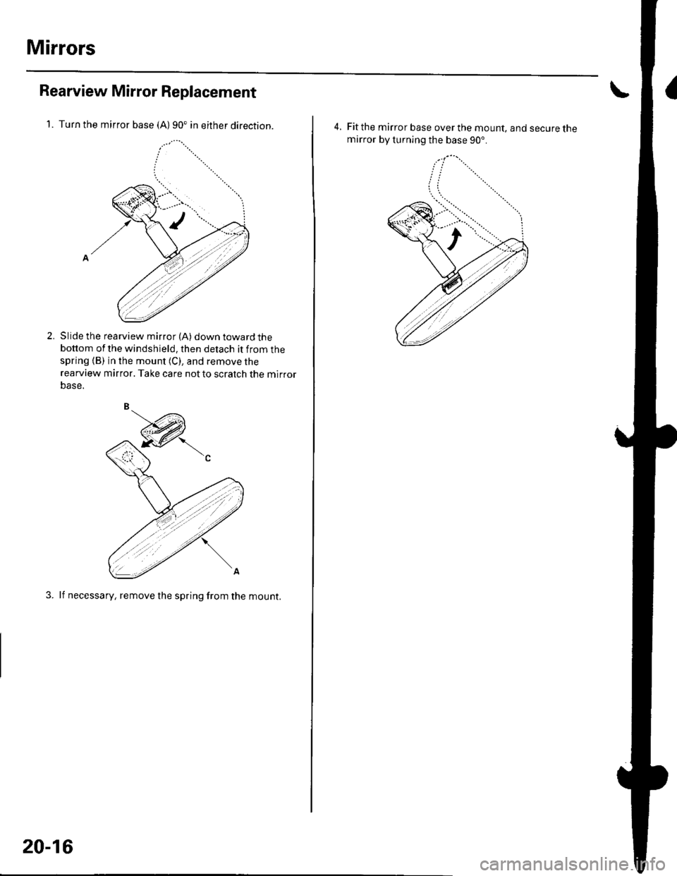
Mirrors
Rearview Mirror Replacement
1. Turn the mirror base (A)90. in either direction.
Slide the rearview mirror (A) down toward thebottom of the windshield, then detach it from thespring (B) in the mount (C), and remove the
rearview mirror. Take care notto scratch the mirror
Dase.
3. lf necessary, remove the spring from the mount.
2.
20-16
4, Fit the mirror base over the mount, and secure themirror by turning the base 90".