g101 HONDA CR-V 1997 RD1-RD3 / 1.G Workshop Manual
[x] Cancel search | Manufacturer: HONDA, Model Year: 1997, Model line: CR-V, Model: HONDA CR-V 1997 RD1-RD3 / 1.GPages: 1395, PDF Size: 35.62 MB
Page 87 of 1395
UNDER.OASH FUSARELAY BOX
INDICATORLIGHT(0.84W)
lPIOSET
526712813
CRUISE CONTROT UNLT 10
11114
COMEINATONL GH'I SWITCH
f7
IRED/BLK
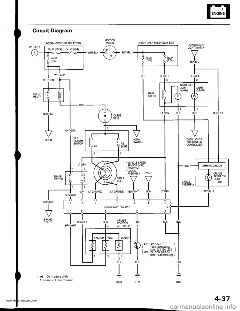
Gircuit Diagram
*: '98 00 models withAutomatic Transmission.
J
BRAK€LGHTSPNK BLK BLK
I L_l
tl
4F /lr,mcern I I
Y{"^ i?tr'.flffi'JF ) l
I
t loN : Pedar rereasedl /l
8LK BLK
TI
G101 G401
CRUISECONTROLACTUATOR
t'BLK
n:
G202
IGNIT ONSWITCHUNDER.HOOD FUSEi RELAY BOX
No 41 (100A) No 42 (404)
4-37
www.emanualpro.com
Page 89 of 1395

Disconnest the lilP connector from the control unit.
Csvity WireTest condition
R€conn€ct tho 14P connGctor to the control unit.
Test: Desired resultPossible cause it result is not obtained
BRNAr'VHTUnder all conditionsCheck for resistance to groundl
There should be 80 - 120 o.
Faulty actuator solenoid
Poor ground (G202)
An open in the wire1BRNUnder all conditionsCheck for resistance to groundl
There should be 40 - 60 0.
11BRN/BLKUnder all conditionsCheck for resistance to ground:
There should be 70 - 110 O.
2GRY
lgnition switch ON (ll),
main switch ON and
brake pedal depressed,
then released
Check for voltage to ground:
There should be 0 V with the pedal
depressed and battery voltage with
the pedal released.
. Faulty brake switch. An open in the wire
BLKUnder all conditionsCheck for continuity to ground:
There should be continuity.
. Poor ground (G401). An open in the wire
5GRNMHT
Brake pedal depressed,
then released
Check for voltage to ground:
There should be battery voltage with
the pedal depressed, and 0 V with
the pedal released.
Blown No.52 1'15 Alfuse in the
under-hood fuse/relay box
Faulty brake switch
An open in the wire
LT GRN/
RED
Set button pushedCheck for voltage to ground:
There should be battery voltage.Blown No. 52 {'15 A} fuse in the
under-hood fuse/relay box
Faulty horn relay
Faulty sevresume switch
Faulty cable reel
An open in the wire7LT GRN/
BLK
Resume button pushed
10RED/BLU
lgnition switch ON lll)Attach to ground:
Cruise indicator light in the gauge
assembly should come on.
Elown bulbBlown No. 25 (7.5 A) tuse in theunder-dash fuse/relay box
Faulty dimming circuit in the gauge
assembly
An open in the wire
ELU^r'r'HT
lgnitjon switch ON {ll}and main switch ON;
raise the front of the
vehicle, block one wheel
and rotate the other
wheel slowly.
Check for voltage between the
ELUA/VHT @ and BLK O terminalsl
There should be 0 - 5 V or more-0 - 5 V or more repeatedly.
Faulty vehicle speed sensor (VSS)
An open in the wire
r3LT GRN
lgnition switch ON {ll}and main switch ONCheck for voltage to ground:
There should be battery voltage.
Blown No. 14 (7.5 A) fuse in theunder-dash fuse/relay box
Faulty main switch
An open in the wire
l4PNK
A'/T: Shift lever in E, EotE
lvl/T: Clutch pedal
releaseo
Check for continuity to ground:
There should be continuity.NOTE: There should be no continu-
ity when the shift lever is in otherpositions or when the clutch pedal is
oepresseo.
Faulty A/f gear position switch 1A,/TlFaulty or misadjusted clutch switch
fi{/r)Poor ground (G101)
An open in the wire
BLU
Start tho engine. turnthe main switch ON, anddrive the vehicle over 25
mph (40 km/h)with the
crurse control set
Check for voltage to ground:
There should be approx.5 V
. Faulty cruise control unit. Shod to ground
*: '98 - 00 models with Automatic Transmission.
4-39
www.emanualpro.com
Page 287 of 1395
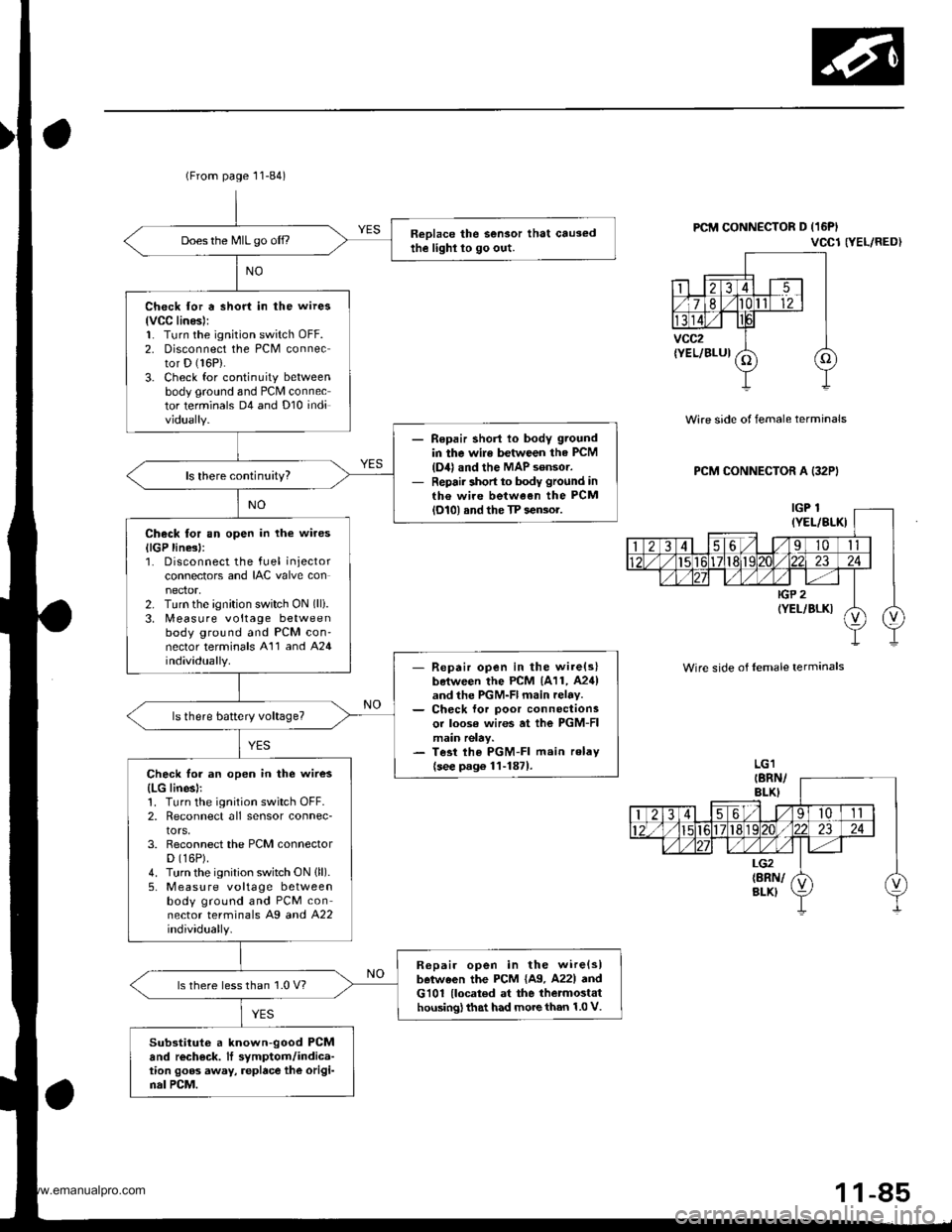
(From page 11-84)
Reolace the Sensor that causedthe lighl lo go out.Does the MIL go off.,
Check for a short in the wires
lvCC linesl:1. Turn the ignition switch oFF.2. Disconnect the PCM connector D (16P).
3. Check for continuity betweenbody ground and PCM connector terminals D4 and Dl0 individually.
Repair shorl lo body ground
in the wile between the PCM
{D4} and the MAP sensor.Repair short to body ground inth€ wire between the PCMlol0l and the TP sensor.
Check tor an open in the wires
llGP line3l:1. Disconnect the fuel injectorconnectors and IAC valve con
2. Turn the ignition switch ON (lli.
3. [,4easure voltage betweenbody ground and PCM con'nector terminals A'11 and A24individually.- Repair open in the wire(slboiween the PCM 1A11, A24)and the PGM-Fl main relav.- Ch€ck lor poor connectionsor loose wires at ihe PGM-FImain relay.- Tesi lhe PGM-FI main relav
{see p.g6 1l-1871.Check for an open in the wires
{LG linesl:1. Turn the ignition switch OFF.2, Reconnect all sensor connec-tors,3. Reconnect the PCM connectorD (16P).
4. Turn the ignition switch ON (ll).
5, M easu re voltage betweenbody ground and PCM connector terminals Ag a^d 422individually.
R6pair open in the wire{slbetween the PCM {A9. A22l andG101 {located at the thetmostathousing) that had more than 1.0 V.
ls there less than 1.0 V?
Substituto a known-good PCMand rech€ck. It symptom/indica-tion goos away, replace the origi-nal PCM.
PCM CONNECTOR D (16PI
VCCl NEL/RED}
Wire side of female terminals
PCM CONNECTOR A (32PI
Wire side of lemale terminals
1 1-85
www.emanualpro.com
Page 289 of 1395
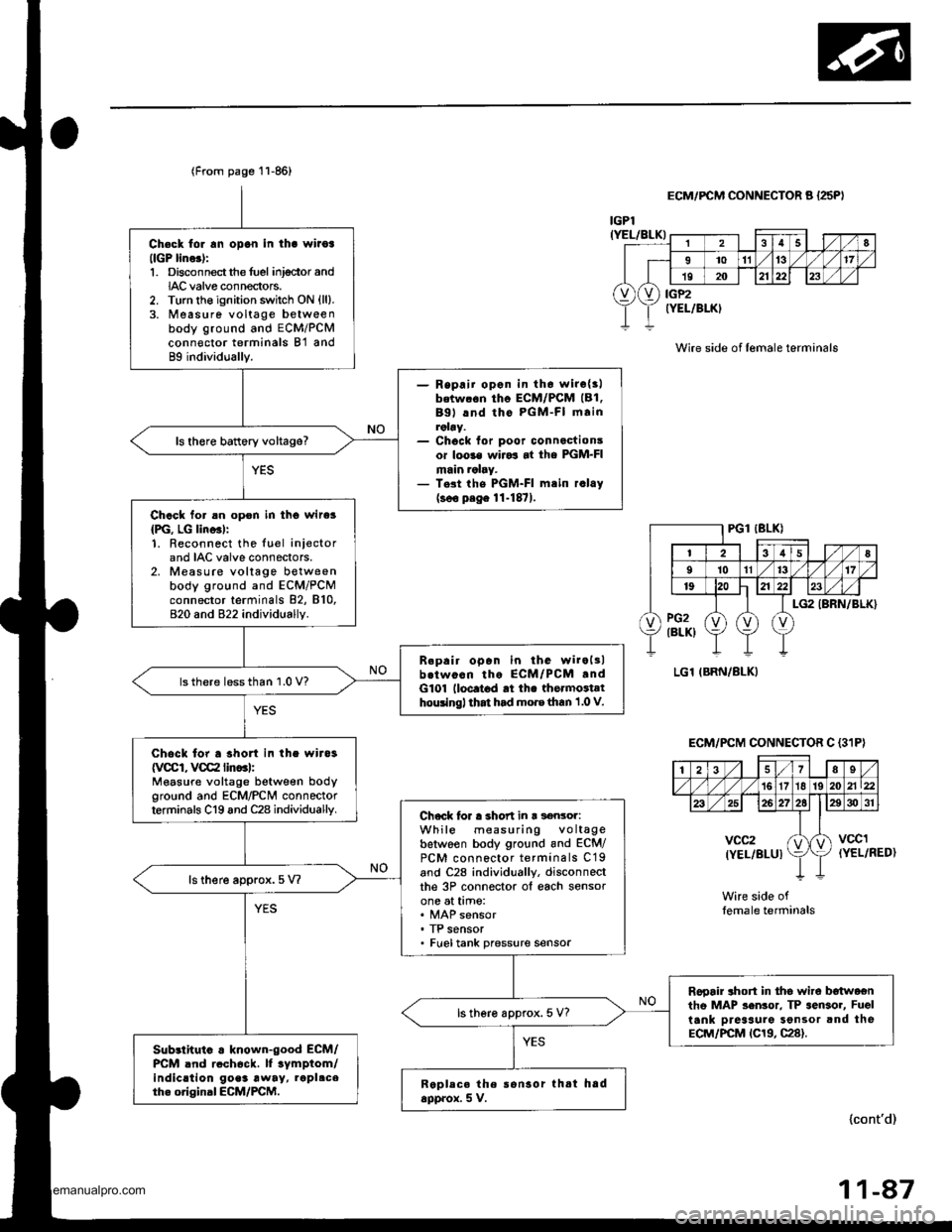
Ch€ck tor rn opon in tha wiioa(lGP lino.):1. Disconnectthe fuel inj€ctor andIAC valve connectors.2. Turn the ignition switch ON {ll}.3. Measure voltage betweenbody ground and ECM/PCMconn€ctor terminals B'l and89 individually.
- Repaii opon in th6 wirc{3lbetw.6n tho ECM/PCM (B1.
Bgl lnd tho PGM-FI mainroby.- Chock for poor connactionsor loo3€ wiJo3 at the PGM-FImain ralry.- T.st the PGM-FI mtin r.lay(soo p.ge 11-1871.
ls there battery voltage?
Chack for an opon in tho wire3
{PG, LG lino3l:1. Reconnect the luel iniectorand IAC valve connectors.2. Measure voltage betweenbody ground and ECM/PCMconnector terminals 82, 810,820 and 822 individually.
B.pair open in the wiroltlb.twocn tho ECM/PCM .ndG101 lloc.t6d rt th. thormoiathouingl that had mo.e than 1 .0 V.
lsthere lessthan 1.0 V?
Chock for a shon in the wira3
{VCCI, VCC2 lin..l:Measure voltage between bodyground and ECM/PCN4 connectorterminals C19 and C28 individuallv.Chock lor a short in r s€nsor:While measuring voltagebetwoen body ground and ECM/PCM connector terminals C19and C28 individually, disconneclthe 3P connector ol each sensorone at time:
. TP sensor. Fueltank pressure sensor
ls there approx.5 V?
Rooair ahort in tho wire b€twoentho MAP sen3or. TP sensor, Fuel
tank Dreaaure Sonsor and theECM/PCM tC19, C28).
ls there approx. 5 V?
Sub3lhuio . known-good ECM/PCM .nd rcch6ck. lf tymptom/indic.tion go.3 away, rapl.ceth. original ECM/PCM.Replece the ronsor thtt hadapprox. 5 V.
(From page 11-86)
lcont'd)
r
28
I1011't317
19202123
vXv) iiP2rELlBLK)
IGPl(YEL/BLK)
ECM/FCM CONNECTOR A {25PI
Wire side of lemale terminals
(YEL/RED)
Wire side oflemale terminals
ECM/PCM CONNECTOR C {3'IP}
| 2i37Es/'t61718 192021\22
26272elE30 31
vcc2(YEL/BLUIktvccl
11-47
www.emanualpro.com
Page 364 of 1395
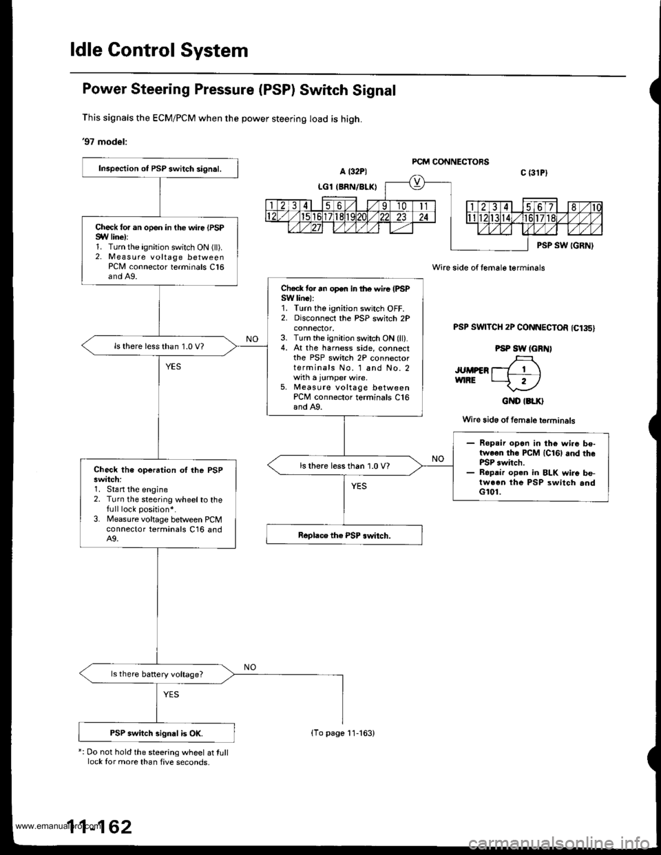
ldle Gontrol System
Power Steering Pressure (PSP) Switch Signal
This signals the ECM/PCM when the power steering load is high.
'97 model:
*: Do not hold the steering wheel at tulllock for more than five seconds,
Wire side of female terminals
PSP SWTTCH 2P CONNECTOR 1C135)
PSP SW (GRN)
JUMPER T_7 1 \vnRE t--f r)
GND IBLK}
Wire 3id6 of female terminals
Inspection ot PSP switch signal.
Check for an open in the wire {PSPSYV line):1. Turn the ignition switch ON (ll).2. Measure voltage betweenPCN4 connector terminals C16and A9.
Check tor an open in lhe wire (PSPSW linel:1. Turn the ignition switch OFF.2. Disconnect the PSP switch 2Pconnecror,3. Turn the ignition switch ON (ll).4. At the harness side, connectthe PSP switch 2P connectorterminals No. 1 and No. 2with a jumper wire.5, Measute voltage betweenPCM connector terminals C16and A9.
ls there less than 1.0 V?
- Ropsir open in the wi.e be-twoon the PCM lcl6l and thePSP switch.- Ropdir open in BLK wire be-tween the PSP switch andG101.
ls there less than 1.0 V?Check the operation oI lhe PSPswitch:1. Stan the engine2. Turn the steering wheelto thefull lock position*.
3. Measure voltage between PCMconnector terminals C16 andA9.
ls there battery voltage?
PSP switch signal is OK.(To page 11-163)
www.emanualpro.com
Page 390 of 1395
![HONDA CR-V 1997 RD1-RD3 / 1.G Workshop Manual
Fuel Supply System
PGM-FI Main Relay (contdl
Troubleshooting
lc(}21PGM.FI MAIN RELAY 7P CONNECTOR
GND
trTr]--Flq
FI,TilI A
Y
Wire side ot female terminals
- Engine will not start.- InsDection ol PG HONDA CR-V 1997 RD1-RD3 / 1.G Workshop Manual
Fuel Supply System
PGM-FI Main Relay (contdl
Troubleshooting
lc(}21PGM.FI MAIN RELAY 7P CONNECTOR
GND
trTr]--Flq
FI,TilI A
Y
Wire side ot female terminals
- Engine will not start.- InsDection ol PG](/img/13/5778/w960_5778-389.png)
Fuel Supply System
PGM-FI Main Relay (cont'dl
Troubleshooting
lc(}21PGM.FI MAIN RELAY 7P CONNECTOR
GND
trTr]--Flq
FI,Til'I A
Y
Wire side ot female terminals
- Engine will not start.- InsDection ol PGM-FI mainrelay and relay harness,
Check fo. an open in the wireIGND linol:1. Turn the ignition switch OFF.2. Disconnect the PGM Fl mainrelay 7P connector.3. Check for continuity betweenthe PGM'FI main relay 7P con-nector terminal No. 3 and bodyground.
Repair opcn in th€ wire betweenthe PGM-FI main relav and G101.
Check tor an open or short in thewiro (BAT line):Measure voltage between thePGM'FI main relay 7P connectorterminal No. 7 and body ground.- Repai. open or short in lhewir6 belween the PGM-FImain relay and the Fl E/M (15Al fu3e.- Replace th6 FIE/M (15 Altus6in th€ under-hood fuse/.6lay
ls there baftery voltage?
Check lor an open or short in thewire (lGl line):L Turn the ignition switch ON (ll).2. Measure the voltage betweenthe PGM-FI main relay 7P connectorterminal No. 5 and bodyground.- Repair open or shorl in thewire between the FGM-FI mainrelay and the No. 13 FUELPUMP 115 A) tuse.- Replaco the No. 13 RJEL PUMP115 A) luse in the und6.-d$hfuso/ relav box.Check for an open or short in thewire {STS line):1. Turn the ignition switch to theSTART (lll) position.NOTE:. M/T: Clutch pedal must bedepressed.. A/T: Transmission in E orElposition.2. Measure the voltage betweenthe PGM-Fl main retay 7Pconnector terminal No. 2 andbody ground.- Repair open or short in thewire betwe€n the PIGM-FI m.inrclay and th€ No. 31 STARTERSlGllAL 17.5 A) tuse.- Repl.ce the No. 31 STARTERSIGNAL 17.5 Al tuse in theunder-dash tuse/relay box.('97 model: To page 11-189)('98 00models:To page 1l 190)
1 1-188
www.emanualpro.com
Page 562 of 1395
![HONDA CR-V 1997 RD1-RD3 / 1.G Workshop Manual
PCM Circuit Diagram (A/T Control System)
97 Model
UNDER.I]OOD FUSAFELAY BOXEATTEFY
_YEL_
T-l ,
TT-l
t_-:
G101
Fr-r.04
P- r.-or..u L_a TMEALOC(BrK€ru -<< calTFoL
P_ *+rr
F- onmrxCFUISECONTFOLUNITf HONDA CR-V 1997 RD1-RD3 / 1.G Workshop Manual
PCM Circuit Diagram (A/T Control System)
97 Model
UNDER.I]OOD FUSAFELAY BOXEATTEFY
_YEL_
T-l ,
TT-l
t_-:
G101
Fr-r.04
P- r.-or..u L_a TMEALOC(BrK€ru -<< calTFoL
P_ *+rr
F- onmrxCFUISECONTFOLUNITf](/img/13/5778/w960_5778-561.png)
PCM Circuit Diagram (A/T Control System)
'97 Model
UNDER.I]OOD FUSAFELAY BOXEATTEFY
_YEL_
T-l ,
TT-l
t_-:
G101
'Fr-r.04
P- r.-or..u L_a TMEALOC(BrK€ru -<< calTFoL
P_ *+rr
F- onmrxCFUISECONTFOLUNITf-"".>
| ["'"]
I l,[-l
III ;,
F_ pw
P_ eLu
F-- enN
UNDER DASN
M 25(7.54)
IGNITONSWITCH UNDEF OASNFUSAFELAYSOX
oowEa-qar. cor.lFo- MooLrE rpcMr F &*1 r*--'l_____O_=_ATP IO! ,ATP . ATD , A-P , A-P , A-PNP lrNo lR 101 103 12 ll
Ar'TGEAR POS]TIONswtcN
14-46
www.emanualpro.com
Page 563 of 1395
![HONDA CR-V 1997 RD1-RD3 / 1.G Workshop Manual
SEr!5OR
V
I
I
t.rh
nf
I
I
1",,
]IYEI]BLK
I-[
lYEITILX
t,
I
l-f?
POSrn0N
P POsITION
II
Ir
SEFVICECHECKCONNECTON
l"8nN
I
I
H
IBLX
{
G101
INTEFLOC( CONIFOL UNITKEY LCICI( SHIFI LOCXACCPUSNSW SOLEIJOIO HONDA CR-V 1997 RD1-RD3 / 1.G Workshop Manual
SEr!5OR
V
I
I
t.rh
nf
I
I
1",,
]IYEI]BLK
I-[
lYEITILX
t,
I
l-f?
POSrn0N
P POsITION
II
Ir
SEFVICECHECKCONNECTON
l"8nN
I
I
H
IBLX
{
G101
INTEFLOC( CONIFOL UNITKEY LCICI( SHIFI LOCXACCPUSNSW SOLEIJOIO](/img/13/5778/w960_5778-562.png)
SEr!5OR
V
I
I
t.rh
nf
I
I
1",,
]'IYEI]BLK
I-[
lYEITILX
t,
I
l-f?
POSrn0N
P POsITION
II
Ir
SEFVICECHECKCONNECTON
l"8nN
I
I
H
IBLX
{
G101
INTEFLOC( CONIFOL UNITKEY LCICI( SHIFI LOCXACCPUSNSW SOLEIJOIO IGI SOLEIOD PPNSW LI] ATPF GND
ENGINECooL,ANTTEMPERATURESENSOF
www.emanualpro.com
Page 564 of 1395
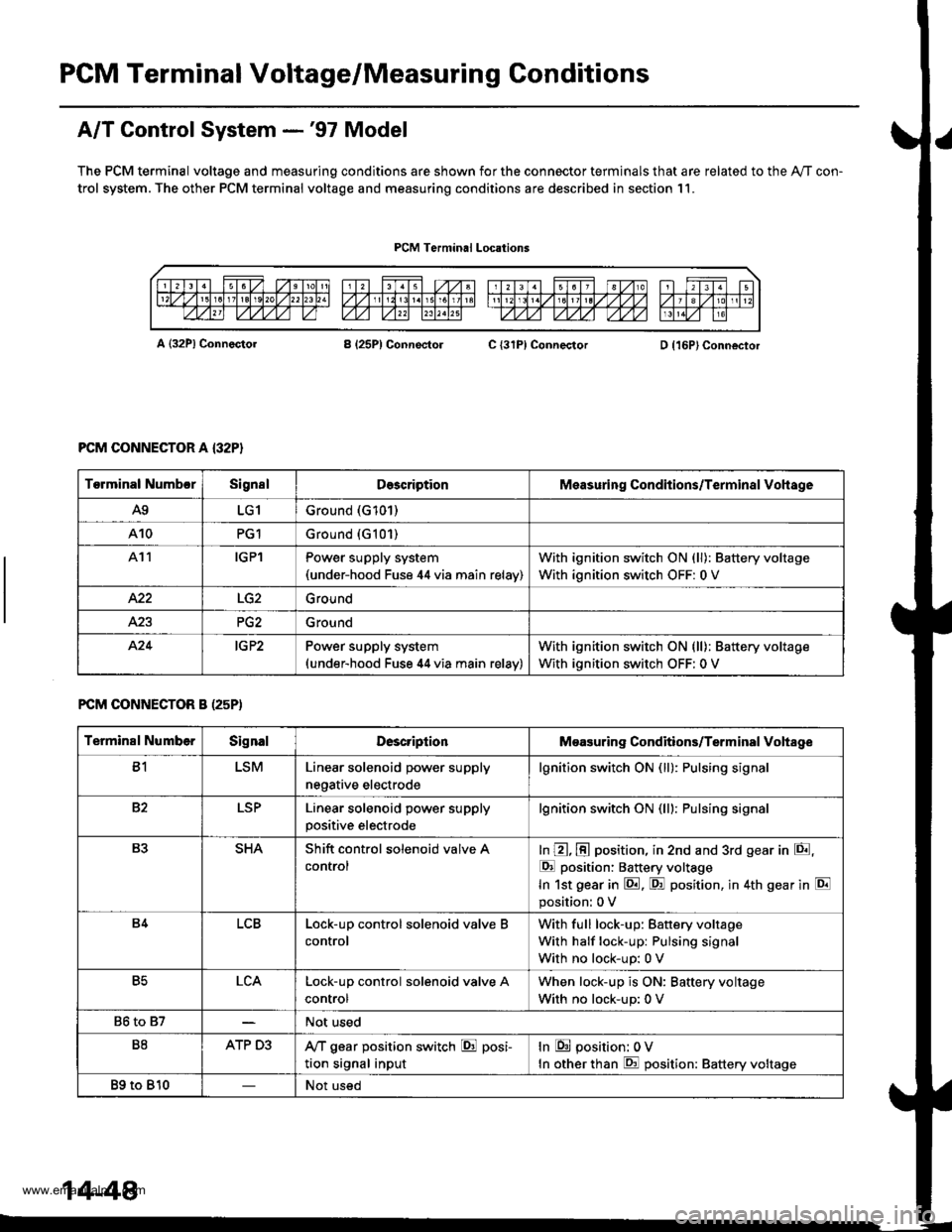
PGM Terminal Voltage/Measuring Conditions
A/T Control System -'97 Model
The PCM terminal voltage and measuring conditions are shown for the connector terminals that are related to the Ay'T con-
trol system. The other PCM terminal voltage and measuring conditions are described in section 11.
PCM Terminal Locations
A {32P} ConnectorB (25P1 ConnectolC {31PI ConnectorD {16P}Connector
PCM CONNECTOR A {32P}
FCM CONNECTOR B (25P)
Torminal NumbcrSignslDescriptionMeasuring Conditions/Terminal Vohage
A9LG1Ground (G101)
A10PG1Ground {G101)
At1IGPlPower supply system(under-hood Fuse 44 via main relav)
With ignition switch ON (ll): Battery voltage
With ignition switch OFF: 0 V
422Ground
Ground
424IG P2Power supply system(under-hood Fuse 44 via main relav)
With ignition switch ON (ll): Battery voltage
With ignition switch OFF: 0 V
Terminal NumberSignalDescriptionMeasuring Conditions/Terminal Vohage
B1LSMLinear solenoid power supply
negative electrode
lgnition switch ON (ll): Pulsing signa
82LSPLinear solenoid power supply
positive electrode
lgnition switch ON (lll: Pulsing signa
B3SHAShift control solenoid valve A
control
In @, @ position, in 2nd and 3rd gear in E,
E position: Battery voltage
In 1st gear in E. F! position, in 4th gear in E
position: 0 V
B4LCBLock-up control solenoid valve B
control
With full lock-up: Battery voltage
With half lock-up: Pulsing signal
With no lock-up: 0 V
B5LCALock-up control solenoid valve A
control
When lock-up is ON: Baftery voltage
With no lock-up: 0 V
86 to 87Not used
B8ATP D3,VT gear position switch E posi-
tion signal input
In E position: 0V
In other than E position: Battery voltage
89 to 810Not used
14-48
www.emanualpro.com
Page 570 of 1395

PCM Terminal Voltage/Measuring Conditions
A/T Control System -'98 - 00 Models
The PCM terminal voltage and measuring conditions are shown for the connector terminals that are related to the A"/T con-
trol system. The other PCM terminal voltage and measuring conditions are described in section 11.
FCM Connector Terminal Localions
NOTE: 819 and C3 terminalsare applied to'99 - 00 models.
o (16Pt
T6rminal NumberSignalDescriptionMeasuring Conditions/Terminal Voltage
A5CRSDownshift signal input from
cruise control unit
When cruise control is used; Pulsing signal
A10scsTiming and adjustment service
check signal (5 V from PCM)
With ignition switch ON (ll) and service check
connector open:5 V
With ignition switch ON (ll) and service check
connector jumped with special tool: 0 V
A14('98 model)
D4 INDD4 indicator light control
{Voltage from PCM turns D4 light
oN)
When ignition switch is first turned ON (ll):
Battery voltage for two seconds
In E position: Battery voltage
A14
('99 - 00 models)
D INDD indicator light control(Voltage from PCM turns D light
oN)
When ignition switch is first turned ON (ll):
Baftery voltage for two seconds
ln E position: Battery voltage
428ILUInterlock control(Voltage from PCM)
When ignition switch ON {ll), brake pedal
depressed, and accelerator pedal released:
Battery voltage
A.32STOP SWBrake switch signal inputBrake pedal pressed; Battery voltage
Brake pedal released: 0 V
FCM CONNECTOR B I25P}
Terminal NumberSignalDescriptionMeasuring Conditions/Terminal Voltage
B1IGPlPower supply circuit from main
relay via under-hood Fuse 44
With ignition switch ON {ll): Battery voltage
With ignition switch OFF: 0 V
82PG1Ground (G101)
B8LSMLinear solenoid power supply
negative electrode
IG P2Power supply circuit from main
relay
With ignition switch ON (ll): Baftery voltage
With ignition switch OFF: 0 V
810PG2Ground (G101)
B17Linear solenoid power supply
positive electrode
With ignition switch ON (ll): Pulsing signal
819
('99 - 00 models)
O/D INDOver-Drive (O/D) OFF indicator
light control
When ignition switch is first turned ON (ll):
0 V for two seconds
O/D OFF indicator light ON:0 V
O/D OFF indicator light OFF: Battery voltage
s20Ground (G101)
B�21VBUBack-up power supply(under-hood Fuse 47)
Always battery voltage
B�22LG2Ground (G101)
14-54
www.emanualpro.com