Ignition switch HONDA CR-V 2000 RD1-RD3 / 1.G Workshop Manual
[x] Cancel search | Manufacturer: HONDA, Model Year: 2000, Model line: CR-V, Model: HONDA CR-V 2000 RD1-RD3 / 1.GPages: 1395, PDF Size: 35.62 MB
Page 580 of 1395
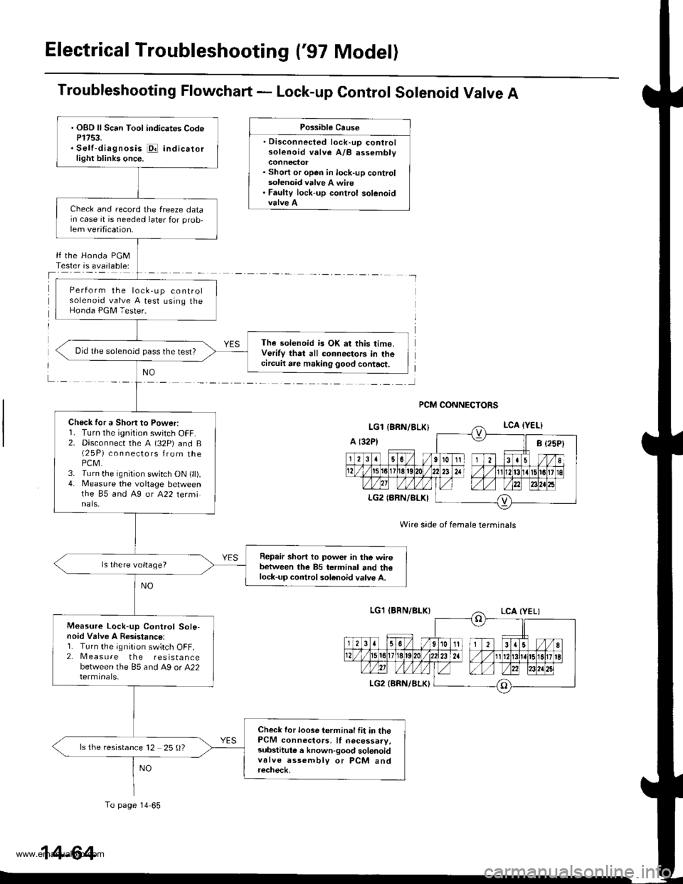
Electrical Troubleshooting ('97 Model)
Troubleshooting Flowchart - Lock-up Control Solenoid Valve A
Possible Cause
. Disconnected lock-up controlsolenoid valve A/B assembly
. Short or open in lock-up controlsolenoid valve A wire. Faulty lock-up control solenoid
lf the Honda PGMTester is available:
NO
Wire side of female terminals
PCM CONNECTORS
. OBD ll Scan Tool indicates CodeP1753.. Self-diagnosis i@ indicatorlight blinks once.
Check and record the freeze datarn case it is needed later for prob-lem verification.
Perform the lock,up controlsolenoid valve A test using theHonda PGM Tester.
The solenoid is OK at this time.Verify that all connectors in thecircuil are making good contact,
Did the solenoid pass the test?
Check for a Short to Power:r. I urn rne tgntUon swttch ut-f.2. Disconnecr the A (32P) and B(2 5P) connectors from thePCM.3. Turn the ignition switch ON (ll).4. Measure the voltage betweenthe 85 and A9 or A22 terminals.
Repair short to power in the wirebetween the 85 terminal and thelock-up control solenoid valve A.
ls there voltage?
Measure Lock-up Control Sole-noid Valve A Resistance:1. Turn the ignition switch OFF.2. Measure the resistancebetween the 85 and A9 or A22
Check for loose terminal fit in thePCM connectors, ll necessary,substitule a known-good solenoidvalve assembly or PCM andrecheck,
ls the resistance 12 25 ()?
To page 14 65
14-64
www.emanualpro.com
Page 582 of 1395
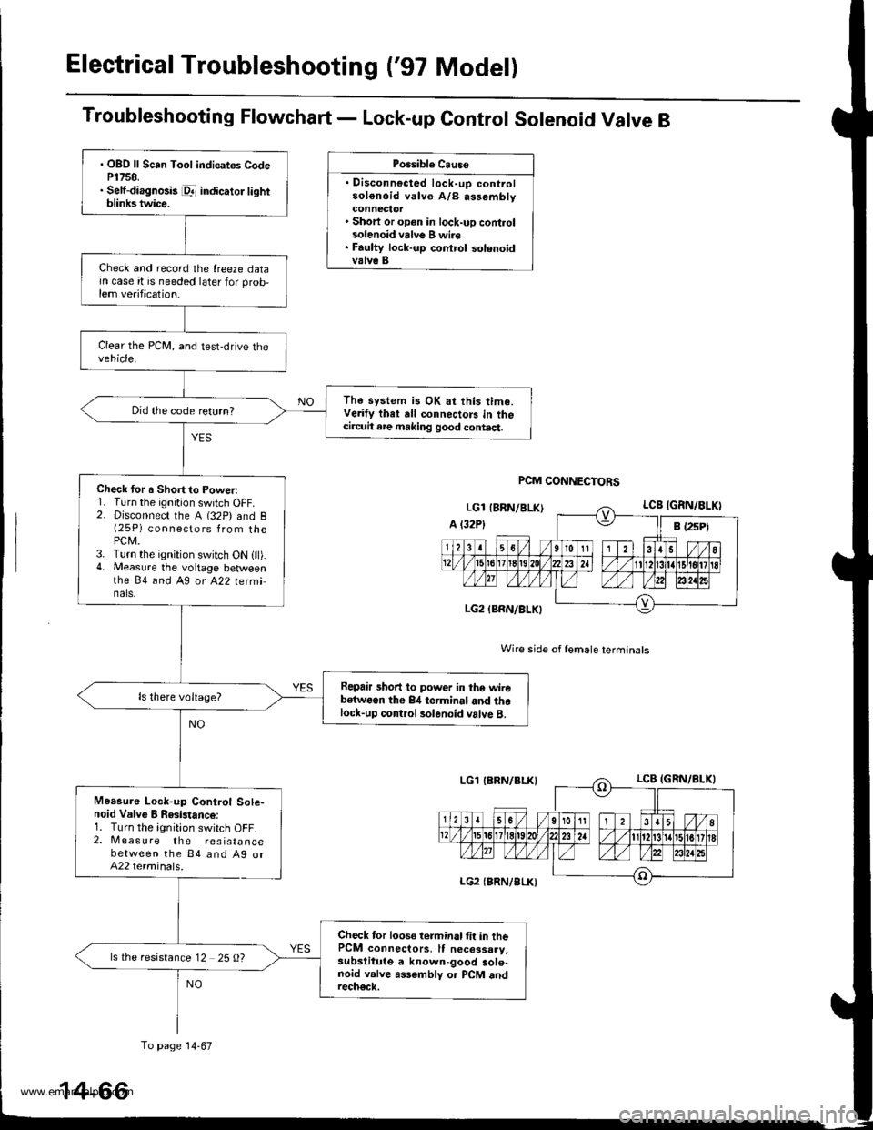
Electrical Troubleshooting ('97 Model)
Troubleshooting Flowchart - Lock-up Control Solenoid Valve B
Possible Causo
. Disconnocted lock-up controlsol€noid valve A/B assembly
. Short or op€n in lock-up control3olenoid vrlve B wi.e. Faulty lock-up control solenoidvalve B
Wire side of female terminals
PCM CONNECTORS
. OBO ll Scan Tool indicates CodeP1758.. Self-diagnosis pr- indicator lightblink3 twice.
Check and record the {reeze datajn case it is needed later for prob,lem verification.
The system is OK at this time.Verify thet dll connectors in thecircuit are making good contact.
Did the code return?
Check tor a Short to Powerl1. Turn the ignition switch OFF.2. Disconnect the A (32P) and B(25P) connectors from thePCM.3. Turn the ignition switch ON {ll).4. Measure the voltage betweenthe 84 and Ag ot A22 tetminals,
Repair short to power in tho wirebstween the 84 terminal and thelock-up control rolenoid valve B.
Measure Lock-up Control Sole-noid Valve B Resistance:1. Turn the ignition switch OFF.2. Measure the resistancebetween the 84 and Ag orA22 terminals.
Check tor loose terminal tit in thePCM connectors, It necessary,subslitute a known-good sole-noid valve assembly o. PCM andrech€ck.
ls the resistance 12 25 O?
To page 14-67
14-66
www.emanualpro.com
Page 584 of 1395
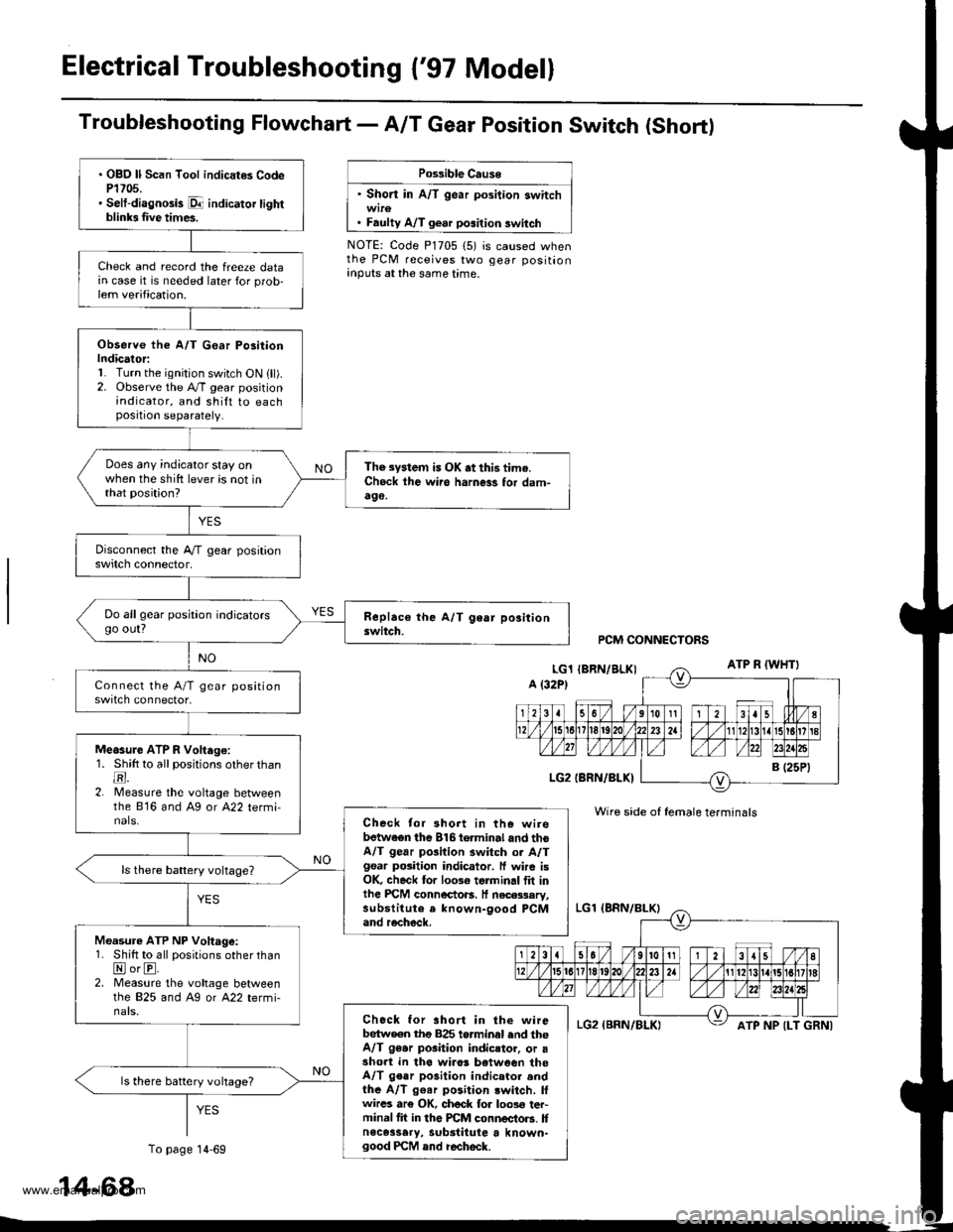
Electrical Troubleshooting {'97 Model}
Troubfeshooting Flowchart- AIT Gear Position Switch (Short)
Po$ible Cause
' Short in A/T gear position switch
. Faulty A/T gear position switch
NOTE: Code P1705 (5) is caused whenthe PCM receives two gear positionanputs at the same time.
. OBO ll Scan Tool indicat€s CodeP1705.' Selt-diagnosis p1- indicator tightblinb Iive times.
Check and record the freeze datain case it is needed later for prob-lem verification.
Observe the A/T G€ar Po3itionIndicator:1. Turn the ignition switch ON lll).2. Observe the A./T gear positionindicator, and shilt to eachposition separately.
Does any indicator stay onwhen the shift lever is not inthat position?
The system is OK .t this time.Ch6ck ihe wii6 harness for dam-490,
Do allgear position indicatorsgo out?
Measure ATP R Voltago:1. Shitt to all positions other thantr.2. lMeasure the voltage betweenthe 816 and Ag or A22 termi-nals.Check tor 3hort in the wirebetwaen the 816torminal and thoA/T gear pGilion switch or A/Tgsar posiiion indicator. ff wire isOK, check for 10036 torminal flt inlhe PICM connectoB. It necessary,substitute a known-9ood PCMand recheck.
Measure ATP NP Voltage:1. Shift to all positions other thanNorE.2. Measure the vohage betweenlhe 825 and Ag or A22 termi-nals.Chock for ahort in the wirebetw€en tho 825 torminal end theA/T 96.r pGition indicstor, or asho.t in tha wiro! b€tween theA/T gear po3ition indicator andthe A/T g€ar position lwitch. lfwircs ar€ OK, ch6ck for loos€ ter-minal fit in the PCM connectors. Itnece3sary, substitute a known-good PCM and recheck.
ls there battery vohage?
PCM CONNECTORS
Wire side of female terminals
ATP NP {LT GRNI
14-68
To page 14-69
www.emanualpro.com
Page 586 of 1395
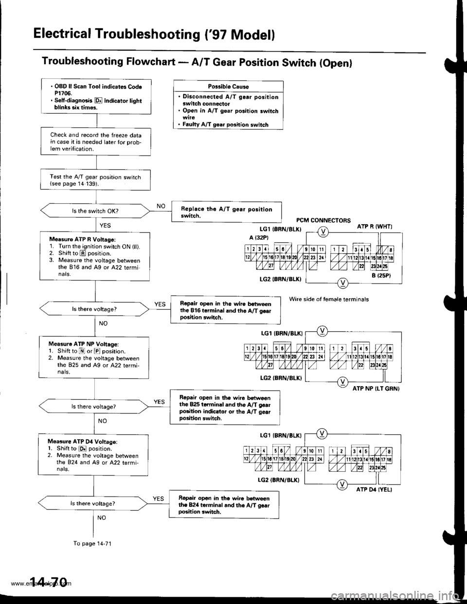
Electrical Troubleshooting ('97 Model)
Troubleshooting Flowchart - A/T Gear position Switch (Openl
Po$iblo C.u3e
. Disconnected A/T gear positionswitch connectol. Open in A/T goar position switch
. Faulty A/T goar position switch
Wire side ot temale terminals
ATP NP ILT GRNI
. OBD ll Scan Tool indicat6 CodeP1706.. Setf-diagnGb Dl indicator tightblinks six tim$.
Check and record the freeze datain case it is needed later for prob-lem verilication.
Test the A,/T gear position switch{see page 14139).
Measu.e ATP R Voltage:'1. Turn the ignition switch ON (ll).2. Shift to E position.3. Measure the voltage betweenthe 816 and Ag or A22 termi-nals.
Repeir op€n in the wire botweenthe 816t€rminaland the A/T g€.rpo3ition switch.
Measure ATP NP Voltage:1. Shift to E or E position.2. Measure the voltage betweenthe 825 and A9 or A22 termi-na ls,
Repai. open in th6 wir6 bctwoanthe 825 terminal and tho A/T gearpolition indicltor or tho A/T gea.Doshion swhch.
Moasure ATP 04 Voltage:1. Shift to E position.2. Measure the voltage betweenthe 824 and A9 or A22 termi-nars,
Ropai. opcn in tho wiro betwoenthe B24 torminal .nd the A/T gcarDosition switch.
To page 14-71
14-70
www.emanualpro.com
Page 588 of 1395
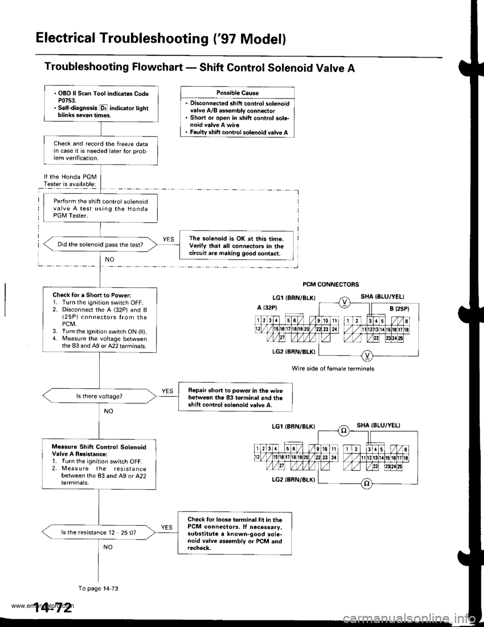
Electrical Troubleshooting ('97 Model)
Troubleshooting Flowchart - Shift Control Solenoid Valve A
. Disconnected shift control solenoidvalve A/8 a$embly connector. Short or open in shift control sole-noid valve A wire
Possible Causo
shift control solenoid valve A
lf the Honda PGMTester is available:
I
PCM CONNECTORS
Wire side of female termin6ls
. OBD ll Scan Tool indicates CodeP0753.. Self-diagnosk E indicator lightblinks seven tim€s.
Check and record the freeze datain case it is needed later for problem verification.
Perform the shift control solenoidvalve A test using the HondaPGM Tester.
The sol€noid is OK at this time.Verify that all connectors in thecircuit are making good contact.
Did the solenoid pass the test?
Check tor a Short to Power:1. Turn the ignition switch OFF.2. Disconnect the A (32P) and B(2 5P) connectors from thePCM.3. Turn the ignition switch ON lll).4. Measure the voltage betweenthe 83 and Ag or A22 terminals.
Repair short to power in the wirebetween the 83 terminal and theshift control solenoid valve A.
Measure Shift Control SolenoidValve A Resistanco:1. Turn the ignition switch OFF.2, Measure the resistancebetween the 83 and A9 or A22termrnals,
Check tor loose terminal tit in thePCM connectors, lf necessaay,subslituie e known-good sole-noid valve assemblv or PCM andrech€ck.
ls the resistance 12 25 {)?
To page l4-73
14-72
www.emanualpro.com
Page 590 of 1395
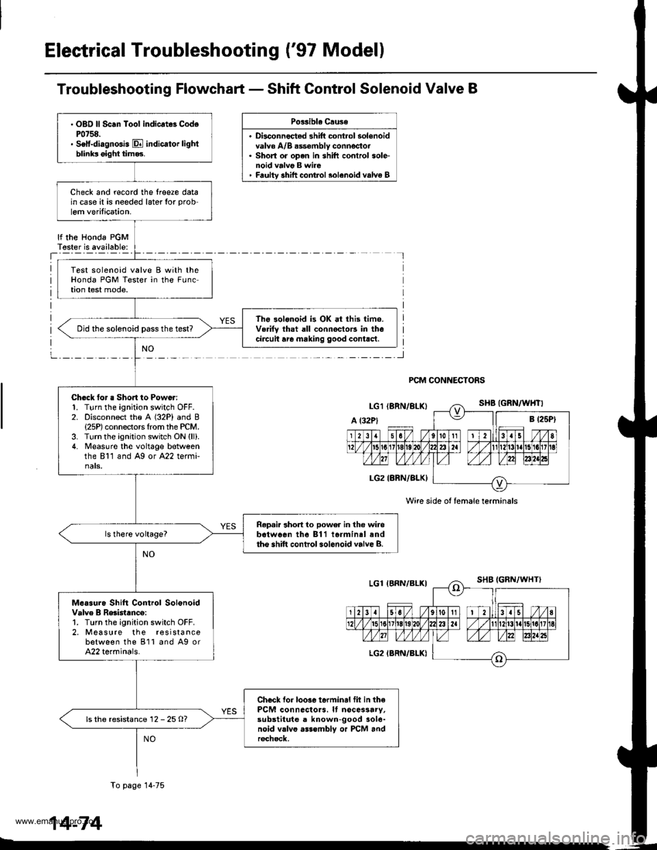
Electrical Troubleshooting ('97 Model)
Troubleshooting Flowchart - Shift Control Solenoid Valve B
Po33ibla Crusa
. Disconnec{ed shift cont.ol solenoidvalve A/B dssombly connector. Short or open in shift conlrol sole-noid valvg B wire' Faultv shift comrol 3olenoid valvo B
lf the Honda PGMT€ster is available:
PCM CONNECTORS
Wire side ot female terminals
. OBO ll Scan Toot indicrt8 CodoP0758.. Setf-diagnGis E indicator lightblinks oight tim93.
Check and r€cord the lreere datain case it is needed later for prob
lem verilication.
Test solenoid valve B with theHonda PGM Tester in the FLrnction test mode.
The 3olonoid is OK at this time.Verifv that all connoctors in thecircuit are making good contlct.Did the solenoid Dass the test?
Chock tor a Sho.t to Power:1. Turn the ignition switch OFF.2. Disconnect the A (32P) and B{25P) connectors Irom the PCM.3. Turn the ignition switch ON (ll).
4. Measuro the voltage botveenthe 811 and Ag or A22 termi-nats.
R.p.ir 3hort to power in the wirebotwo€n the 811 iormin.l andtho shift control sol.noid valve B.
M.6sure Shift Control SolonoidValve B Reaistanco:1. Turn the ignition switch OFF.2. Measure the r€sistancebetween the 811 and A9 orA22 terminals.
Checl lor loosc terminal fil in thePCM connactors. It nocessarv,substitute a known-good aole-noid vllvo asssmbly or PCM andr6chsck,
ls the resistance 12 - 25 O?
To page 14-75
14-74
www.emanualpro.com
Page 599 of 1395
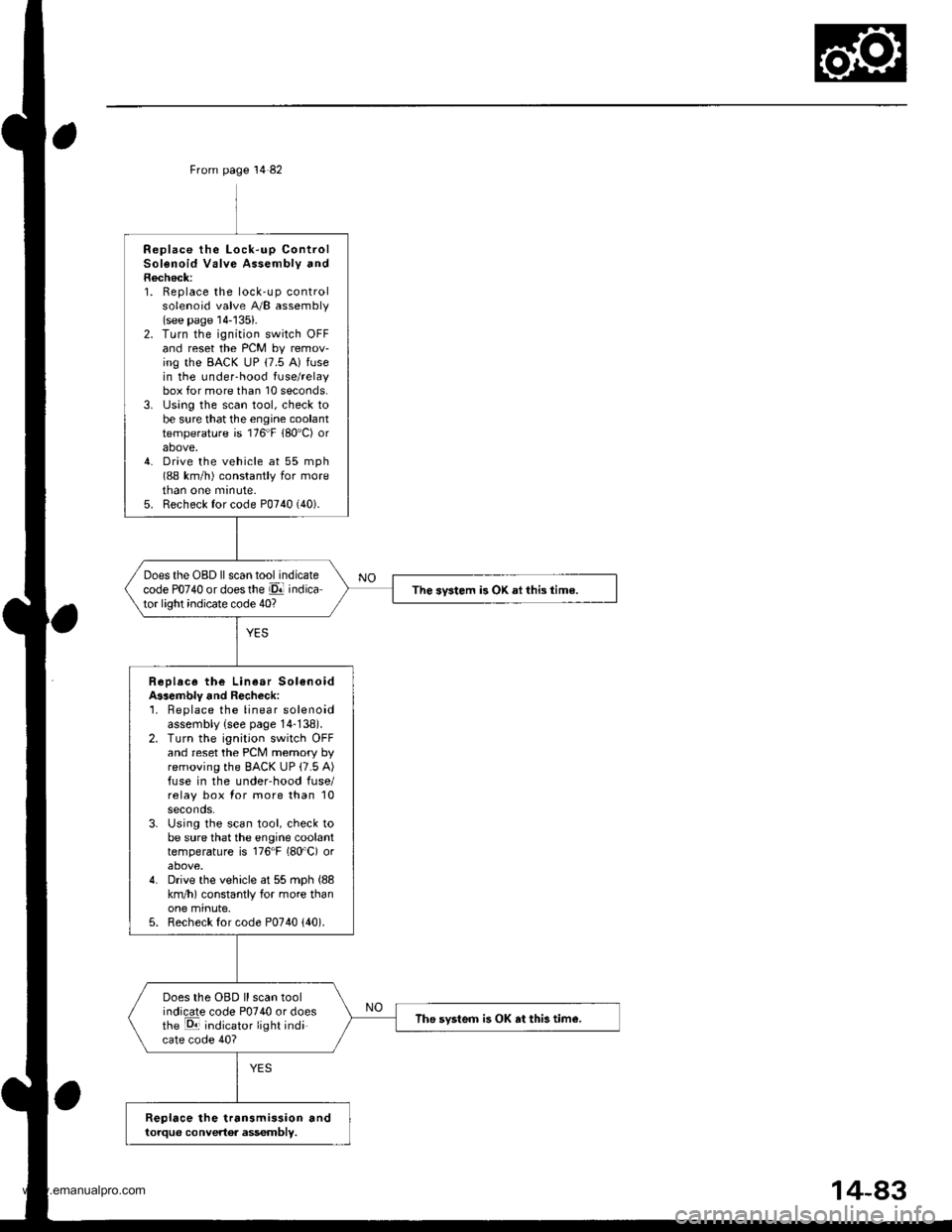
From page 14 82
Replace the Lock-up ControlSolenoid Valve Assembly andRecheck:1. Replace the lock-up controlsolenoid valve A/B assembly(see page 14-'135).2. Turn the ignition switch OFFand reset the PCM by remov-ing the BACK uP (7.5 A) fusein the under-hood fuse/relaybox for more than 10 seconds.3. lJsing the scan tool, check tobe sure that the engine coolanttemperature is 176"F 180'C) orabove,4. Drive the vehicle at 55 mph(88 km/h) constantly for moretnan one mrnute.5. Recheck for code P0740 (40).
Does the OBD ll scan tool indicatecode PO74O or doesthe El indicator light indicate code 40?The svstem is OK ai this time.
Replace the Linear Sol€noidA$embly and Recheck:'1. Beplace the linear solenoidassembly {see page 14-138).2. Turn the ignition switch OFFand reset the PCM memory byremoving the BACK UP (7.5 A)fuse in the underhood fuse/relay box for more than 10seconds.3. Using the scan tool, check tobe sure that the engine coolanttemperature is 176"F (80'C) orabove.4. Drive the vehicle at 55 mph (88
km/h) constantly for more thanone minute,5. Recheck for code P0740 {40).
Does the OBD ll scan toolindicate code P0740 or doesthe E indicator light indicate code 40?
The svsteo is OK at this tim€.
Replace the transmission andtorque convertor assembly.
www.emanualpro.com
Page 601 of 1395
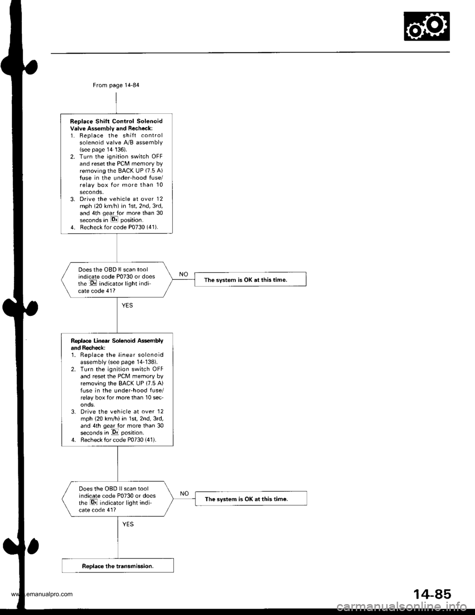
Replace Shift Control Solenoidvslve Assembly and Recheck:1. Replace the shift controlsolenoid valve A/B assembly(see page'14 136).2. Turn the ignition switch OFFand reset the PCM memory byremoving the BACK UP (7.5 A)fuse in the under-hood fuse/relay box for more than 10seconds.3. Drive the vehicle at over 12mph (20 km/h) in 1st,2nd,3rd,and 4th qear for more than 30seconds in E position.
4. Recheck for code P0730 (41).
Does the OBD ll scan toolindicate code P0730 or doesthe E indicator light indicate code 41?
The svstem is OK at this time.
Replace Linea. Solenoid Ass€mblyand Recheck:1. Replace the linear solenoidassembly lsee page 14-138).2. Turn the ignition switch OFFand reset the PcM memory byremoving the BACK UP 17.5 A)fuse in the underhood fuse/relay box tor more than 10 sec'onos.3. Drive the vehicle at over '12
mph {20 km/h) in 1st,2nd,3rd,and 4th geal for more than 30seconds in -Da position.
4. Recheck for code P0730 (41).
Does the OBD llscan toolindicate code P0730 or doesthe Di indicator light indi-cate code 41?
The syslem is OK at this time.
From page 14-84
14-85
www.emanualpro.com
Page 602 of 1395
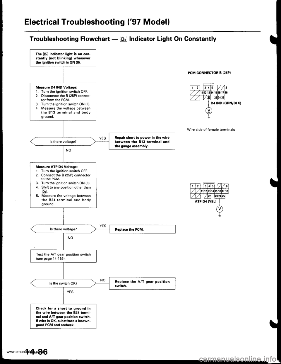
Electrical Troubleshooting ('97 Modell
Troubleshooting Flowchart - E Indicator Light On Constantly
PCM CONNECTOR B I25PI
IGRN/8LKI
Wire side of temale terminals
The E indicator light is on con-stantly {not blinking) wheneverthe ignition switch b ON (lll.
Measure D4 IND Voltage:'1.
2.
3.4.
Turn the ignition switch OFF.Disconnect the I (25P) connec-tor lrom the PCM.Turn the ignition switch ON lll).Measure the voltage betweenthe 813 terminal and bodygrouno,
Ropair short to powor in the wirebetwean tho B13 terminal andtho gauge assembly.
Maa3ure ATP D4 Voltage:1. Turn the ignition switch OFF.2. Connect the B (25P) connectorto the PCM.3. Turn the ignition switch ON (ll).
4. Shiftto any position other than
E.5. Measure the voltage betweenthe 824 terminal and bodyground.
Test the lVT gear position switch(see page '14 139).
Check lor a short to g.ound inthe wire betwoen tho B2rl te.minal and A/T gear position switch.It wira i3 OK, substitute a known-good PCM and r€check.
www.emanualpro.com
Page 603 of 1395
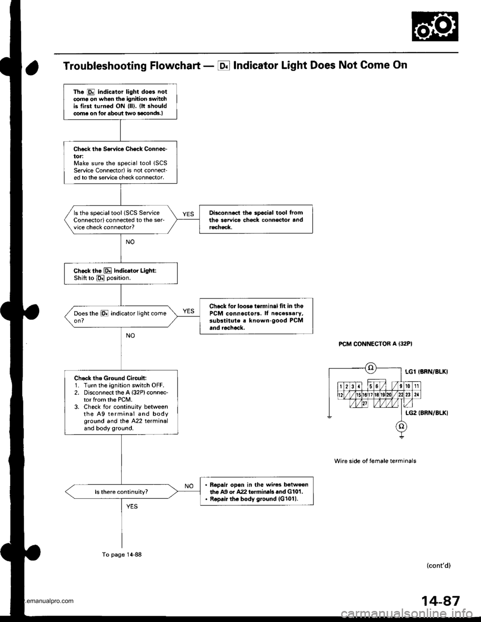
Troubleshooting Flowchart - E Indicator Light Does Not Come On
PCM CONNECTOR A {32PI
Wire side ot temale terminals
LGl IBRN/BLKI
LG2 (BRN/BLKI
(cont'd)
The E indicator light doos notcomo on whon the ignition switchis first turned ON {lll. (lt shouldcome on lor about two aaclnd!.I
Check the Sorvice Check Connec-toriMake sure the special tool 1SCSService Connector) is not connect-ed tothe service check connector,
Di3connect the spccial tool tromthe servica chock connoctor andrechsck.
ls the specialtool (SCS ServiceConnectorlconnected to the ser-vice check connector?
chock th. El Indicator Light:Shift to E position.
Ch6ck for looie terminal fit in thePCM connoctors. ll nocesssry,sub.titule a known-good PCMand rechock.
Check the Ground Circuit:1. Turn the ignition switch OFF.2. Disconnect the A {32P)connec-tor from the PCM.3. Check for continuity betweenthe A9 terminal and bodyground and tho A22 terminaland body ground.
R€pair opon in the wire3 betweenthe Ag or A22 torrninab and G101.Repair the body ground (G1011.
To page 14-88
14-87
www.emanualpro.com