Use engine oil HONDA CR-V 2000 RD1-RD3 / 1.G Owner's Manual
[x] Cancel search | Manufacturer: HONDA, Model Year: 2000, Model line: CR-V, Model: HONDA CR-V 2000 RD1-RD3 / 1.GPages: 1395, PDF Size: 35.62 MB
Page 920 of 1395

Rear Suspension
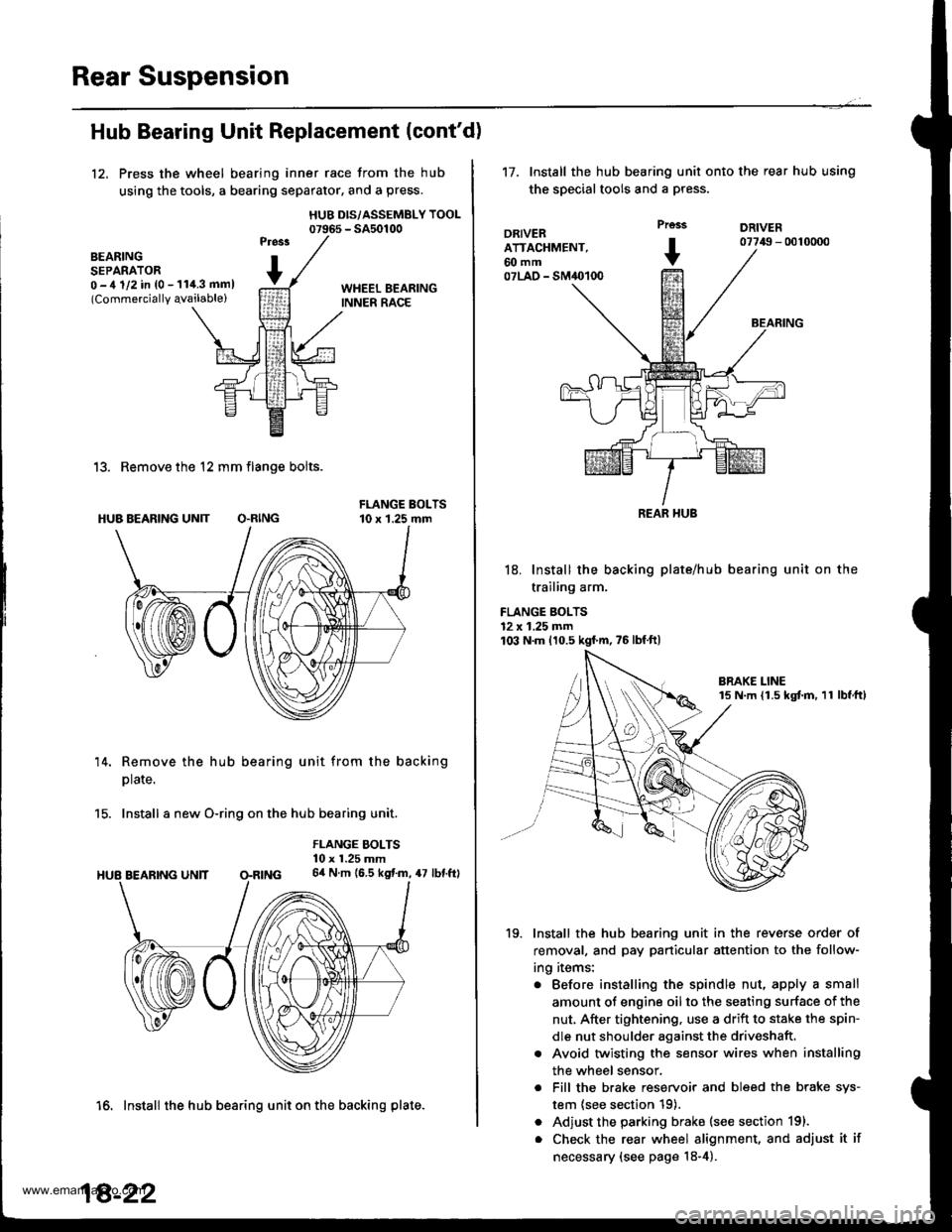
Hub Bearing Unit Replacement (cont'd)
12, Press the wheel bearing inner race from the hub
using the tools, a bearing separator, and a press.
HUB DIS/ASSEMBLY TOOL07965 - SA50100
BEARINGSEPARATOR0 -,t 1/2 in {0 - 11i1.3 mml(Commercially qvailable)
13. Remove the 12 mm flange bolts.
HUB BEARING UN]T O.RING
14. Remove the hub bearing unit from the backing
plate.
15. Install a new O-ring on the hub bearing unit.
FLANGE BOLTS10 x 1.25 mm64 N.m (6.5 kgf.m, 47 lbf.ftl
16. Install the hub bearing unit on the backing plate.
18-22
't7.Install the hub bearing unit onto the rear hub using
the special tools and a press.
DRIVERATTACHMENT,60 mm07LAO - SM40100
Prcss
+
DRIVER07749 - 0010000
BEARING
18. Install the backing plate/hub
trailing arm.
FLANGE BOLTS12 x 1.25 mm103 N.m 110.5 kgf'm,75lbfft)
bearing unit on the
19. Install the hub bearing unit in the reverse order of
removal, and pay particular attention to the follow-
ing items:
. Before installing the spindle nut, apply a small
amount of engine oil to the seating surface of the
nut, After tightening, use a drift to stake the spin-
dle nut shoulder against the driveshaft.
. Avoid twisting the sensor wires when installing
the wheel sensor,
. Fill the brake reservoir and bleed the brake sys-
tem {see section 19).
. Adjust the parking brake (see section 191.
. Check the rear wheel alignment, and adjust it if
necessary (see page 18-4).
REAR HUB
www.emanualpro.com
Page 1174 of 1395
![HONDA CR-V 2000 RD1-RD3 / 1.G Owners Manual
Connector ldentification and Wire Harness Routing
Engino Wire Harness
Connecto; or
Terminal
Number of
CavitiesLocationConneqts toNotos
c101
c102
c103
c 104
c105
c105
c106
c 107
c 108
c 109
c]10
c1ll HONDA CR-V 2000 RD1-RD3 / 1.G Owners Manual
Connector ldentification and Wire Harness Routing
Engino Wire Harness
Connecto; or
Terminal
Number of
CavitiesLocationConneqts toNotos
c101
c102
c103
c 104
c105
c105
c106
c 107
c 108
c 109
c]10
c1ll](/img/13/5778/w960_5778-1173.png)
Connector ldentification and Wire Harness Routing
Engino Wire Harness
Connecto; or
Terminal
Number of
CavitiesLocationConneqts toNotos
c101
c102
c103
c 104
c105
c105
c106
c 107
c 108
c 109
c]10
c1l'l
c112
c113
c't 14
cl16
cl16
c117
c118
c119
c120
c121
c't22
c't23
c't25
cl26
cl27
cr 28
cl29
c130
c131
c132
c 133
c134
c134
c135
c 136
10
6
1
2
1
2
1
10
20
31
16
22
l0
l0'14
14
1
Left side of engine compartment
Left side of engine compartment
Middle of engine
Middle of engine
Left side of engine compartment
Left side of engine compartment
Middle of engine
Middle of engine
Middle of engine
Middle of engine
Middle of engine
Middle of engine
Middle of engine
Middle of engine
Middle of engine
Middle of engine
Middle of engine
Middle of engine
Middle of engine
Middle of engine
Middle of engine
Right side of engine
Middle of engine
Behind right kick panel
Under right side of dash
Under right side of dash
Under right side of dash
Under right side of dash
Under right side of dash
Right side of engine
Right side of engine
Middle of engine
Middle of engine
Middle of engine
Middle of engine
Middle of engine
Middle of engine
Left side of engine compartment
Middle of engine
Middle of engine
Main wire harness (C304)
Main wire harness (C305):'97 - 98 models
No. 1 fuel injector
Crankshaft speed fluctuation (CKF) sensor
Alternator
Alternator
Engine oil pressure switch
No.2 fuel injector
Evaporative emission (EVAP) purge
control solenoid valve
No. 3 fuel injector
No. 4 fuel injector
Primary heated oxygen sensor(Primary HO2S) (sensor 1)
Radiator fan switch
Coolant temperature sending unit
Engine coolant temperature (ECT) sensor
Mainshaft speed sensor
Lock-up control solenoid valve
Back-up light switch
Shift control solenoid valve
Linear solenoid valve
Countershaft speed sesnsor
Starter solenoid
Distributor
Junction connector
PCM
ECIWPCM
ECM/PCM
ECM/PCM
Main wire harness (C,|:}1)
IVT gear position switch
Vehicle speed sensor (VSS)
Throttle position (TP) sensor
MAP sensor
ldle air control (lAC)valve
lntake air temperature (lAT) sensor
Junction connector
Junction connector
Power steering pressure (PSP) switch
Junction connector
Knock sensor (KS)
A/r
USA
Canada
Alr
AlT
M/'r
Afi
'97mooel
'97 model'98 - 00
mooets
'99 - 00
models
T101
r102
Left side of en0ine companment
Right side of engine compartment
Alternator
Under-hood fuse/relay box
G101Middle of engineEngine ground, via engine wire harness
23-14
www.emanualpro.com