housing HONDA CR-V 2000 RD1-RD3 / 1.G Service Manual
[x] Cancel search | Manufacturer: HONDA, Model Year: 2000, Model line: CR-V, Model: HONDA CR-V 2000 RD1-RD3 / 1.GPages: 1395, PDF Size: 35.62 MB
Page 484 of 1395
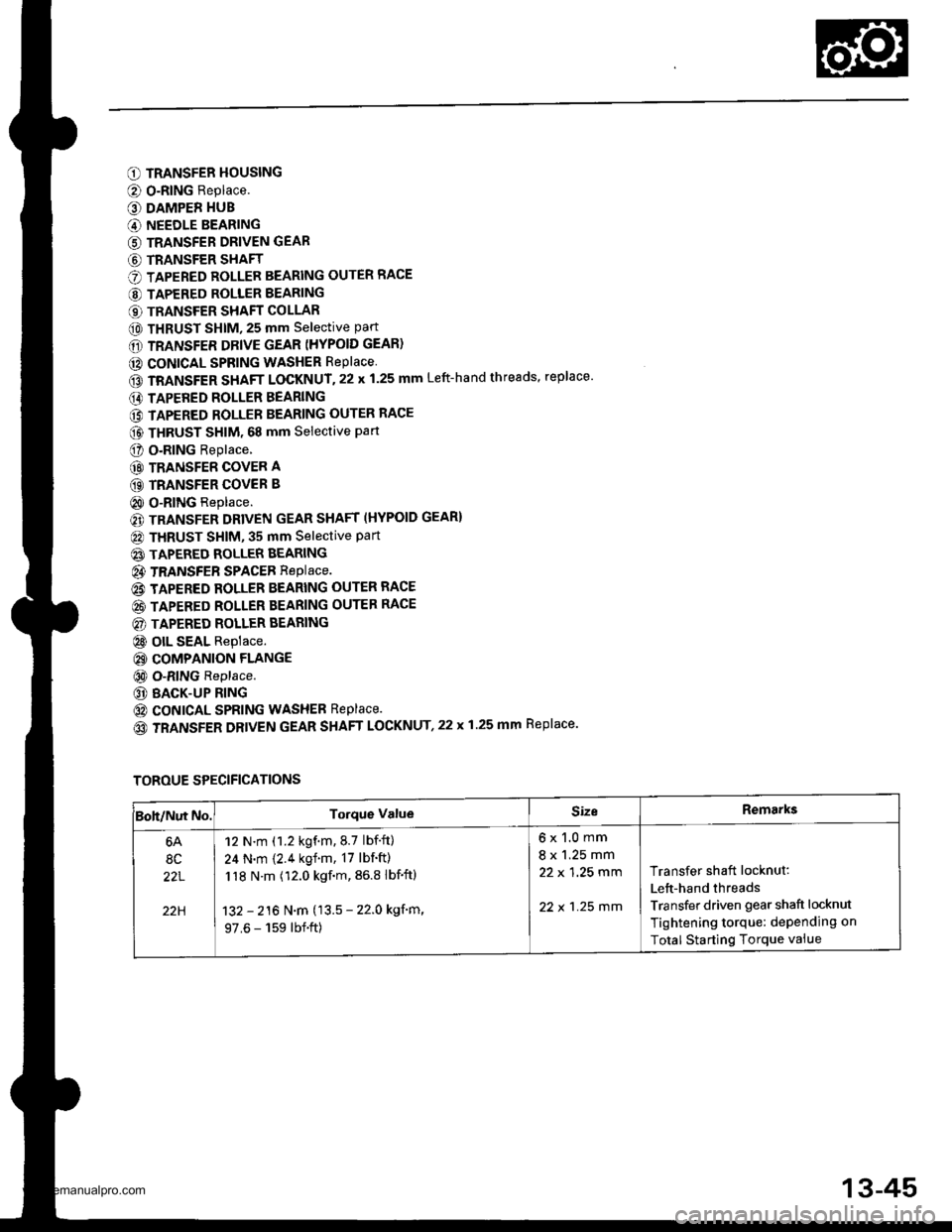
O TRANSFER HOUSING
@ O-RING Replace.
O DAMPER HUB
G) NEEDLE BEARING
G) TRANSFER DRIVEN GEAR
G) TRANSFER SHAFT
O TAPERED ROLLER BEARING OUTER RACE
@ TAPERED ROLLER BEARING
€) TRANSFER SHAFT COLLAR
@ THRUST SHIM, 25 mm selective part
6D TRANSFER DRIVE GEAR (HYPOID GEAR)
@ CONICAL SPRING WASHER RePlace
GD TRANSFER SHAFT LOCKNUT.22 x 1.25 mm Left-hand threads, replace'
E) TAPERED ROLLER BEARING
@ TAPERED ROLLER BEARING OUTER RACE
@ THRUST sHlM. 68 mm selective part
O o.RlNG Replace.
@ TRANSFER COVER A
GD TRANSFER COVER B
@ O-RING Replace.
€) TRANSFER DRIVEN GEAR SHAFT (HYPOID GEAR}
@ THRUST SHIM, 35 mm Selective Part
@ TAPERED ROLLER BEARING
@ TRANSFEB SPACEB RepIace.
@ TAPERED ROLLER BEARING OUTER RACE
@ TAPERED ROLLER BEARING OUTER RACE
@) TAPERED ROLLER BEARING
@ olL SEAL Replace.
@ COMPANION FLANGE
@ O-RING Replace.
@ BACK-UP RING
@ coNtcAL SPRING WASHEB Replace.
(o TRANSFER DRIVEN GEAR SHAFT LOCKNUT,22 x 1.25 mm Replace.
TOROUE SPECIFICATIONS
Boh/Nut No.Torque ValueSizeRemarks
6A
8C
22L
22H
12 N.m (1.2 kgf.m.8.7 lbf.ft)
24 N.m {2.4 kgf.m, 17 lbf'ft)
118 N.m (12.0 kgf.m, 86.8 lbf'ftl
132 - 216 N.m (13.5 - 22.0 kgf'm,
97.6 - 159 lbf.ft)
6x1.0mm
8 x 1.25 mm
22 x 1 ,25 mm
22 x 1 .25 mm
Transfer shaft locknut:
Lett-hand threads
Transfer driven gear shaft locknut
Tightening torque: dePending on
Total Starting Torque vaiue
13-45
www.emanualpro.com
Page 485 of 1395
Transfer Assembly
Inspection
NOTE: To prevent damage to the transfer housing,
always use soft jaws or equivalent materials between
the transfer housing and the vise.
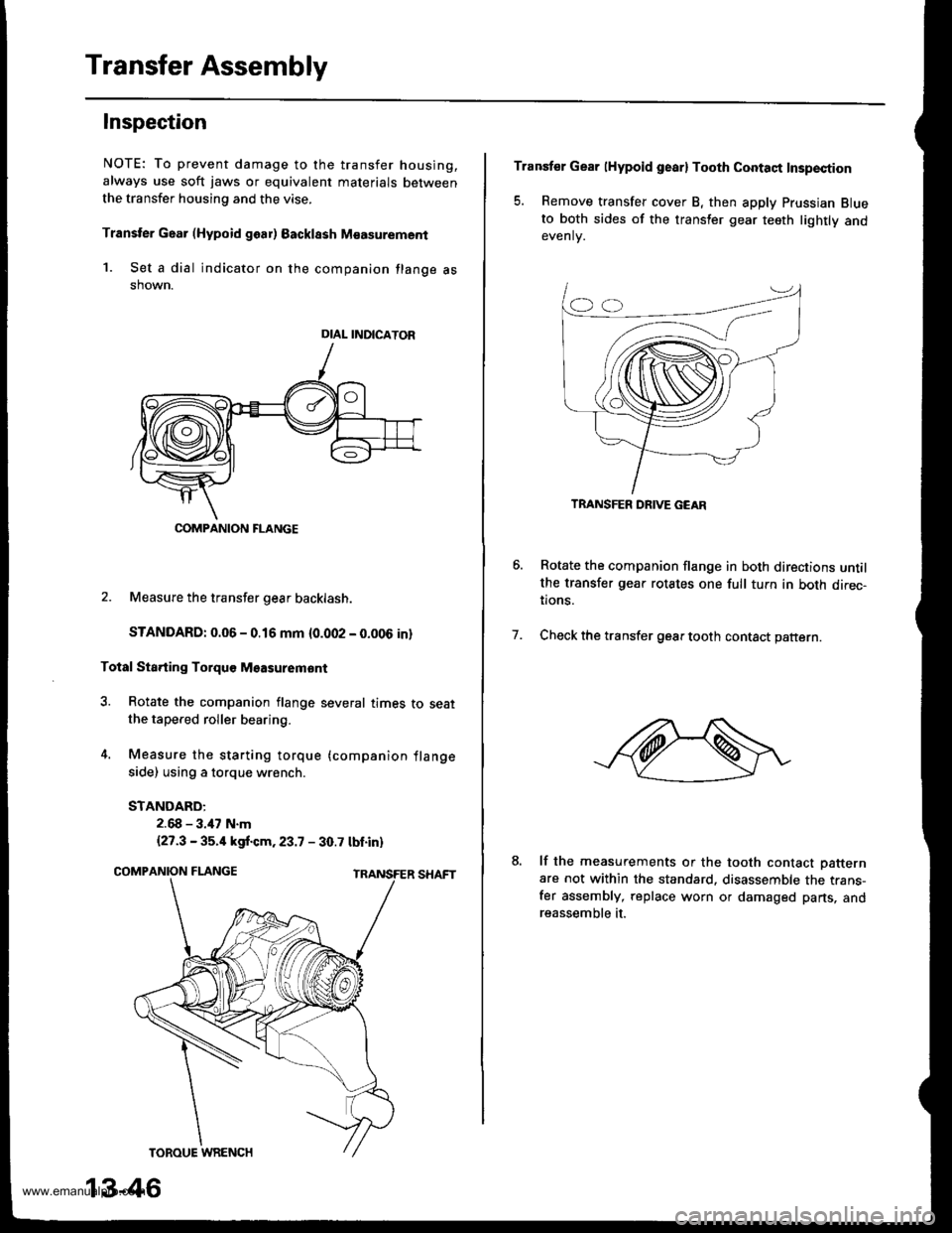
Transter Gaar (Hypoid goar) Backlssh M€asurement
1. Set a dial indicator on the companion flange asshown.
2. Measure the transfer gear backlash.
STANDARD: 0.06 - 0.16 mm {0.002 - 0.006 in}
Total Sta.ting Torquo Msasuremont
3. Rotate the companion flange several times to seatthe tapered roller bearing.
4. Measure the starting torque (companion flange
side) using a torque wrench.
STANDARD:
2.68 - 3.47 N.m
{27.3 - 35.4 kgf.cm.23.7 - 30.7 tbt.in)
DIAL INDICATOR
COMPANION FLANGE
13-46
Transfer Gear lHypoid gearl Tooth Contaqt Insp€ction
5. Remove transfer cover B, then apply Prussian Blueto both sides of the transler gear teeth lightly andevenlv.
Rotate the companion flange in both directions untilthe transfer gear rotates one full tuln in both direc-tions.
Check the transfer gear tooth contact pattern.7.
lf the measurements or the tooth contact Datternare not within the standard. disassemble the trans-fer assembly, replace worn or damaged parts, andreassemble it.
TRANSFER DRIVE GEAR
www.emanualpro.com
Page 486 of 1395
Disassembly
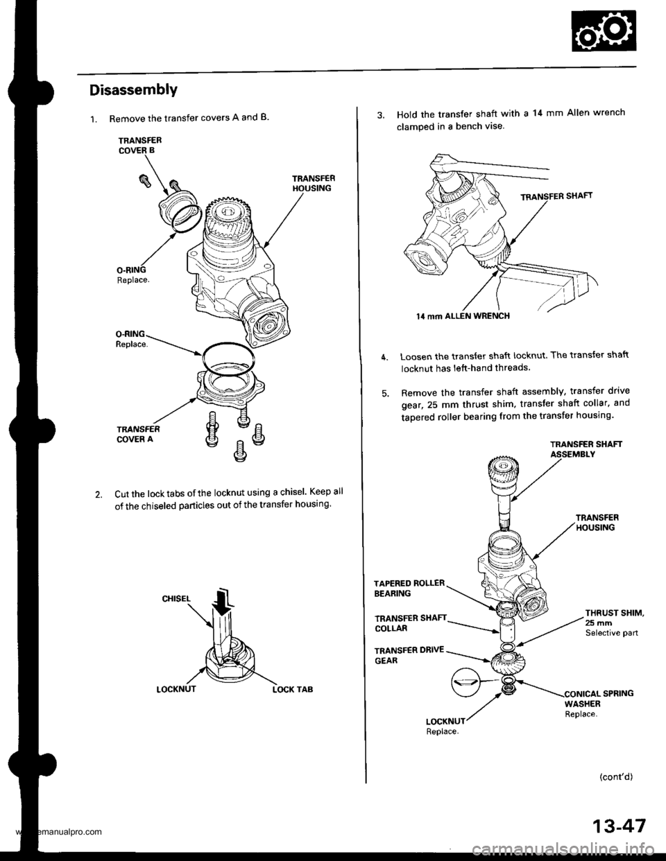
1.Remove the transfer covers A and B.
TRANSFER
TRANSFEF
Replace.
Cut the locktabs ofthe locknut using a chisel. Keep
of the chiseled particles out of the transfer housing
LOCKNUTLOCK TAB
atl
3. Hold the transfer shaft with a 14 mm Allen wrench
clamped in a bench vise.
Loosen the transter shaft locknut. The transfer shaft
locknut has lett-hand threads.
Remove the transfer shaft assembly, transfer drive
gear,25 mm thrust shim. transfer shaft collar. and
tapered roller bearing from the transfer housing.
TRANSFER SHAFTASSEMBLY
TAPERED ROLLERBEARING
TRANSFER SHAFTCOLLAR
TRANSFER DRIVE
GEAR
THRUST SHIM,25 mmSelective pan
(cont'd)
14 mm ALLEN WRENCH
13-47
www.emanualpro.com
Page 487 of 1395
Transfer Assembly
Disassembly (cont'd)
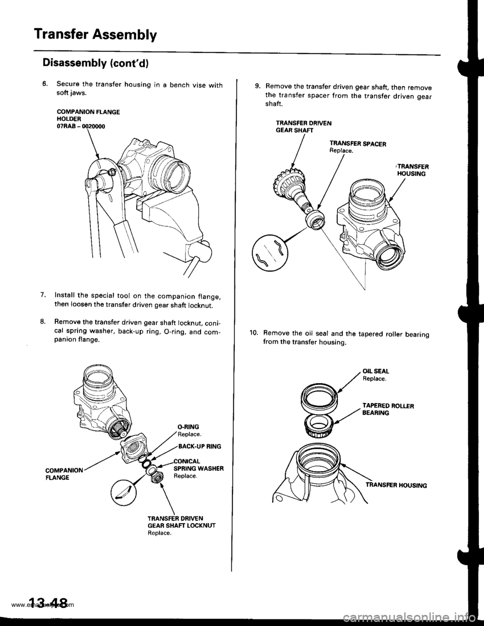
Secure the transfer housing in a bench vise withsoft jaws.
COMPANION FLANGEHOLDER07RAA -
Install the special tool on the companion flange,then loosen the transfer driven gear shaft locknut.
Remove the transfer driven gear shaft locknut, coni-cal spring washer, back-up ring, O-ring, and com-psnion flange.
7.
TRANSFER DRIVENGEAR SHAFT LOCKNUTReolace,
13-48
9. Remove the transfer driven gear shaft, then removethe transfer spacer from the transfer driven gearshaft.
TRANSFER ORIVENGEAR SHAFT
Remove the oil seal and the tapered roller bearingfrom the transfer housing,
OIL SEALReplace.
TAPEREO ROLIIRAEARING
TRANSFER HOUSING
www.emanualpro.com
Page 490 of 1395
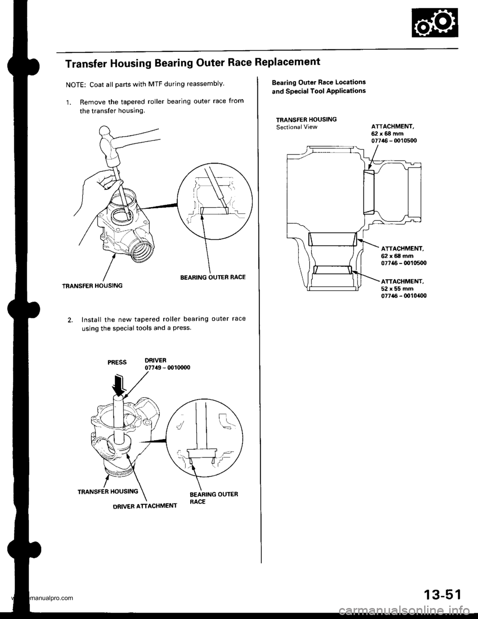
Transfer Housing Bearing Outer Race Replacement
NOTE: Coat all parts with MTF during reassembly.
1. Remove the tapered roller bearing outer race from
the transfer housing.
TBANSFER HOUSING
Install the new tapered roller bearing outer race
using the special tools and a press
DRIVER07749 - 0o1(xD0
TRANSFER HOUSINGBEARING OUTERRACE
J
i=
\l
DRIVER ATTACHMENT
13-51
Bealing Outer Race Locations
and Special Tool APP|ications
TRANSFER HOUSINGSectionalViewATTACHMENT,62x68mm07746 - 0010500
ATTACHMENT,62x68mm07?a6 - 0010500
ATTACHMENT,52x55mm07715 - 0010400
www.emanualpro.com
Page 492 of 1395
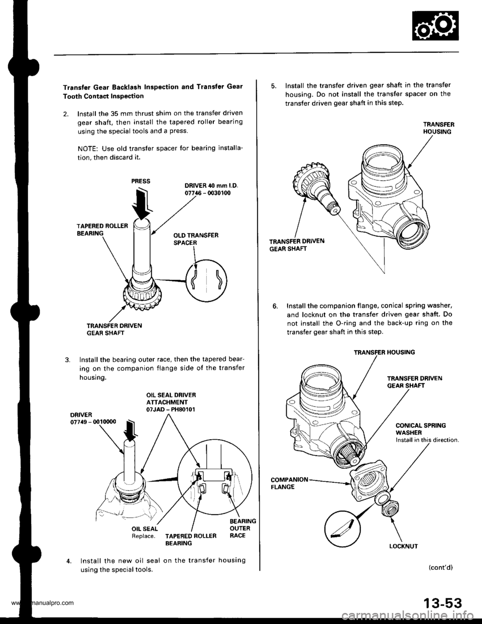
Transter Gear Backlash Inspection and Transfer Gear
Tooth Contaqt Inspection
2. lnstall the 35 mm thrust shim on the transfer driven
gear shaft, then install the tapered roller bearing
using the special tools and a press.
NOTE: Use old lransfer spacer for bearing installa-
tion, then discard it.
TRANSFER DRIVENG€AR SHAFT
Install the bearing outer race, then the tapered bear-
ing on the companion flange side ot the transfer
housing.
3.
OIL SEAL DRIVERATTACHMENT07JAD - PH80101DRIVER077/tg - 001qt00
Replace.TAPERED ROLLERBEARING
Install the new oil seal on the transfer housing
using the special tools.
5. Install the transfer driven gear shaft in the transfer
housing. Do not install the transfer spacer on the
transfer driven gear shaft in this step.
TRANSFERHOUSING
Installthe companion flange. conical spring washer,
and locknut on the transfer driven gear shaft. Do
not install the O-ring and the back-up ring on the
transfer gear shaft in this step.
6,
COMPANIONFLANGE
CONICAL SPRING
direction.
(cont'd)
13-53
TRANSFER HOUSING
WASHER
www.emanualpro.com
Page 493 of 1395
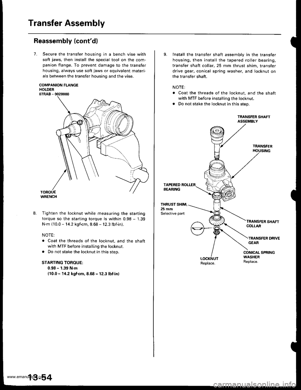
Transfer Assembly
Reassembly (cont'd)
7.Secure the transfer housing in a bench vise with
soft jaws, then install the special tool on the com-
panion flange. To prevent damage to the transfer
housing, always use soft jaws or equivalent materi-
als between the transfer housing and the vise.
COMPANION FLANGEHOLDER07RAB - 0020000
WRENCH
8. Tighten the locknut while measuring the starting
torque so the starting torque is within 0.98 - 1.39
N.m {10.0 - 14.2 kgf.cm. 8.68 - 12.3 lbf.in).
NOTE:
. Coat the threads of the locknut, and the shaft
with MTF before installing the locknut.
. Do not stake the locknut in this step.
STARTING TOROUE:
0.98 - 1.39 N.m(10.0 - 14.2 kgf.cm, 8.68 - 12.3 lbf.in)
9.Install the transfer shaft assembly in the transfer
housing, then install the tapered roller bearing,
transfer shaft collar,25 mm thrust shim, transfer
drive gear, conical spring washer, and locknut on
the transfer shaft.
NOTE:
. Coat the threads of the locknut, and the shaft
with MTF before installing the locknut.
. Do not stake the locknut in this step.
TRANSFER SHAFTASSEMBLY
TRANSFER
THRUST SHIM.25 mmSelective part
COLLAR
TRANSFER DRIVEGEAR
CONICAL SPRINGWASHERReplace.Replace.
www.emanualpro.com
Page 496 of 1395
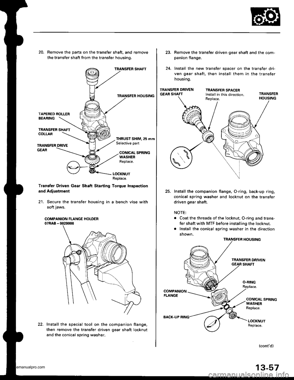
20. Remove the parts on the transfer shaft, and remove
the transfer shatt from the transfer housinq.
TRANSFER SHAFT
TRANSFER HOUSING
TAPERED ROLLERBEARING
TRANSFER SHAFTCOLLAR
TMNSFER DRIVEGEAR
THRUST SHIM, 25 mmSelective part
CONICAL SPRINGWASHERReplace.
LOCKNUTReplace.
Transter Driven Gear Shaft Starting Torque Inspection
and Adlustment
21. Secure the transfer housing in a bench vise with
soft iaws.
Install the special tool on the companion flang€,
then remove the transfer driven gear shaft locknut
and the conical spring washer.
COMPANION FLANGE HOLDER
22.
BACK.UP
Remove the transter driven gear shaft and the com-
panion flange.
Install the new transfer spacer on the transfer dri-
ven gear shaft, then install them in the transfer
housing.
TRANSFER DRIVENGEAR SHAFTTRANSFER SPACERInstall in this direction.TRANSFER
25.Install the companion flange, O-ring, back-up ring,
conical spring washer and locknut on the transfer
driven gear shaft.
NOTE:
. Coat the threads of the locknut, O-ring and trans-
fer shaft with MTF before installing the locknut.
. Install the conical spring washer in the direction
shown.
TRANSFER HOUSING
O.RING
COMPANIONFLANGECONICAL SPRINGWASHERReplace.
LOCKNUTReplace.
(cont'd)
13-57
www.emanualpro.com
Page 497 of 1395
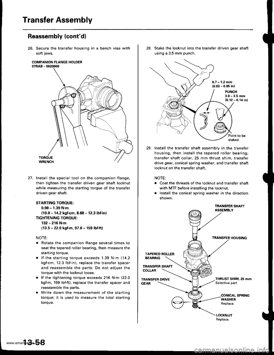
Transfer Assembly
Reassembly (cont'dl
26. Secure the transfer housing in a bench vise with
soft jaws.
COMPANION FLANGE HOLDER07RAB - 002tD00
27. Install the special tool on the companion flange.
then tighten the transfer driven gear shaft locknut
while measuring the starting torque of the transfer
driven gear shaft.
STARTING TOROUE:
0.98 - 1.39 N.m
{10.0 - 1i1.2 kgf.cm, 8.68 - 12.3 lbf in}
TIGHTENING TOROUE:
132 - 216 N.m
(13.5 - 22.0 kgf.m, 97.6 - 159 lbf.ft)
NOTE:
. Rotate the companion flange several times to
seat the tapered roller bearing, then measure the
startrng torque.
. lf the starting torque exceeds 1.39 N.m (14.2
kgf.cm, 12.3 lbf.in), .eplace the transfer spacer
and reassemble the parts. Do not adjust the
torque with the locknut loose.
. lf the tightening torque exceeds 216 N.m (22.0
kgf.m, 159 lbf'ft), replace the transfer spacer and
reassemble the parts.
. Write down the measurement of the starting
torque: it is used to measure the total starting
torque.
28. Stake the locknut into the transfer driven oear shaft
using a 3.5 mm punch.
0.7 - 1.2 mm(0.03 - 0.05 inl
Point to bestaked.
Install the transfer shaft assemblv in the transfer
housing, then install the tapered roller bearing,
transfer shaft collar, 25 mm thrust shim, transfer
drive gear, conical spring washer, and transfer shaft
locknut on the transfer shaft.
NOTE:
. Coat the threads of the locknut and transfer shaft
with MTF before installing the locknut.
. lnstall the conical spring washer in the direction
snown.
TMNSFER SHAFTASSEMBLY
TRANSFER HOUSING
TAPERED ROLLERBEARING
TRANSFER SHAFTCOLLAR
TRANSFER DRIVEGEAR
PUNCH3.0-3.5 mm10.12 - 0.1a inl
THRUST SHIM, 25 mmSelective part
CONICAL SPRINGWASHEBReplace.
LOCKNUTReplace.
29.
www.emanualpro.com
Page 498 of 1395
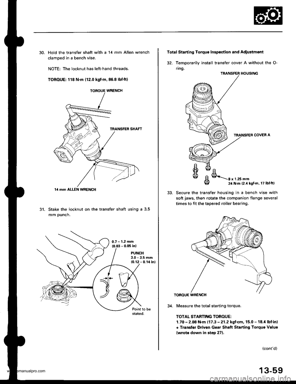
30. Hold the transfer shaft with a 14 mm Allen wrench
clamDed in a bench vise.
NOTE: The locknut has left-hand threads.
TOROUE: 118 N.m (12.0 kgt'm,86.8 lbf'ft)
31. Stake the locknut on the transfer shaft using a 3.5
mm Dunch.
PUNCH3.0 - 3.5 mm{0.12 - 0.14 inl
14 mm ALLEN WRENCH
Totsl Starting Torquo Inspoction and Adiustment
32. Temoorarilv install transfer cover A without the O-
ring.
TRANSFER HOUSING
TRANSFER COVER A
oEl
€lE/Ehvc/E\\g8 x 1 .25 mm24 N.m (2.4 kg{ m, 17 lbtftl
5t.Secure the transfer housing in a bench vise with
soft jaws. then rotate the companion flange several
times to fit the tapered roller bearing,
TOROUE WR€NCH
34. Measure the total starting torque.
TOTAL STARNNG TOROUE:
1.70 - 2.08 N.m 117.3 - 21.2 kgf.cm, 15.0 - 18.i1 lbf inl
+ Transter Driven Gear Shaft Starting Torque Value
(wrot€ down in step 27).
(cont'd)
13-59
www.emanualpro.com