clutch HONDA INTEGRA 1994 4.G Workshop Manual
[x] Cancel search | Manufacturer: HONDA, Model Year: 1994, Model line: INTEGRA, Model: HONDA INTEGRA 1994 4.GPages: 1413, PDF Size: 37.94 MB
Page 536 of 1413
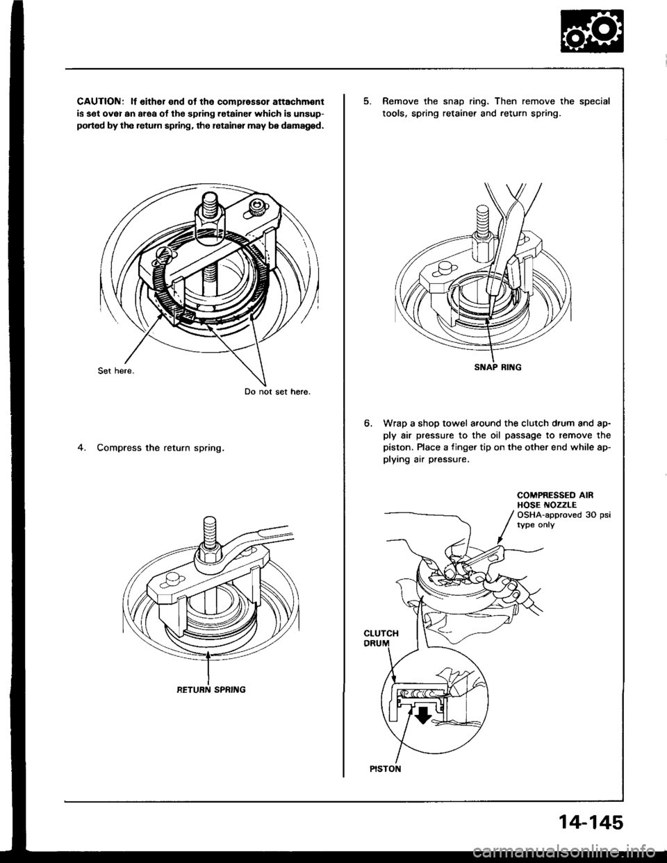
CAUTION: lf either end ot the comprassol attachm€nt
is sel ovsl an araa ol the spdng retaine. which is unsup-
ported by the retum spring. the letainer may be damag6d,
4. Compress the return spring.
Do not set horo.
RETURN SPRING
5.Remove the snap ring. Then remove the special
tools, spring retainer and return spring.
Wrap a shop towel around the clutch drum and ap-
ply air pressure to the oil passage to remove the
piston. Place a finger tip on the other end while ap-
plying air p.essure.
6.
COMPRESSED AIRHOSE NOZZLEOSHA-approved 30 psirype onry
CLUTCH
S AP RING
PISTON
14-145
Page 537 of 1413
Clutch
Reassembly
NOTE:
a Clean all psrts thoroughly in solvent or carburetorcleaner. and dry them with compressed air.a Blow out all passages.
a Lubricate all pans with ATF before .eassembly.
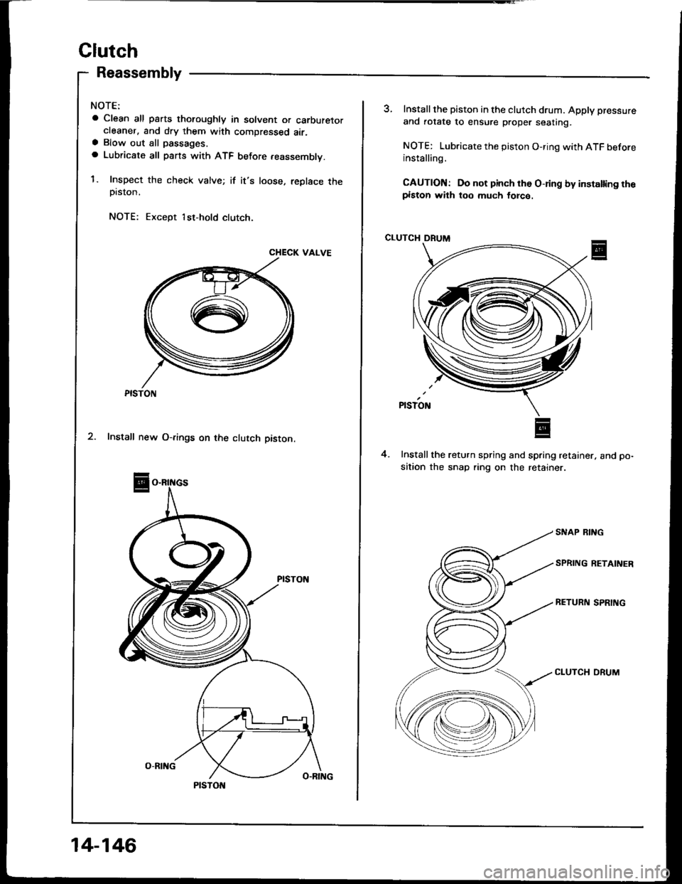
1. Inspect the check valve; if it's loose, replace theprston,
NOTE: Except 1st-hold clutch.
CHECK VAIVE
PISTON
14-146
3, Installthe piston in the clutch drum. Apply pressure
and rotate to ensure proper seating.
NOTE: Lubricate the piston O-ring with ATF beforeinstalling,
CAUTION: Do not pinch rh6 O-ring by installing th€piston with too much lorco.
CLUTCH DRUM
Installthe return spring and spring retainer. and po-
sition the snap ring on the retainer
4.
SNAP RING
SPRING RETAINER
RETURN SPRING
CLUTCH ORUM
Page 538 of 1413
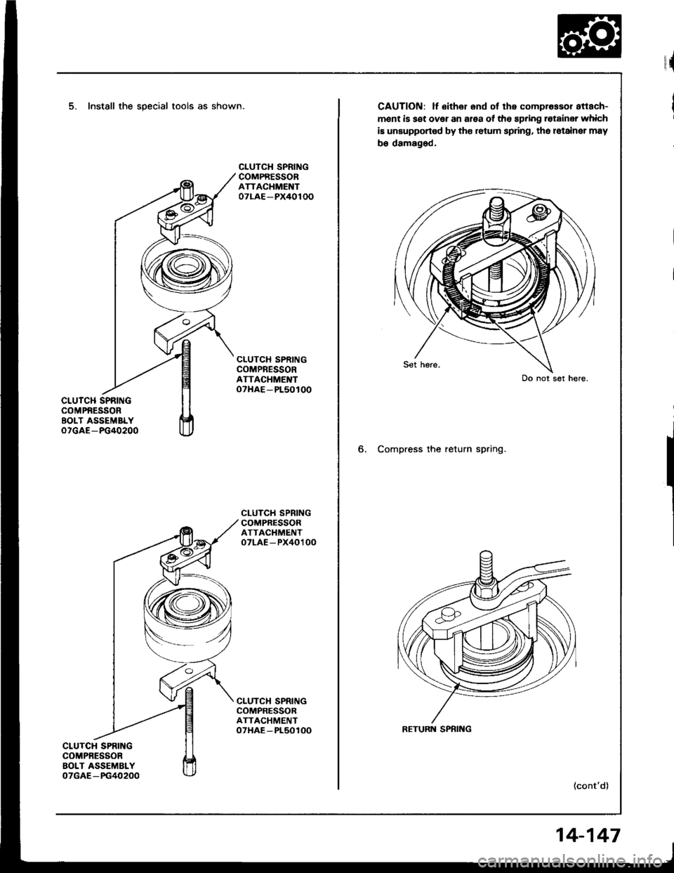
5, Install the special tools as shown.
CLUTCH SPRINGCOMPNESSORBOLT ASSEMBLYoTGAE-FG40200
CLUTCH SPRINGCOMPRESSORAOLT ASSEMBLY07GAE-PG40200
CLUTCH SPRINGCOMPRESSORATTACHMENT07LAE-PX40100
CLUTCH SPRINGCOMPRESSORATTACHMENToTHAE-Pl50100
CLUTCII SPRINGCOMPRESSORATTACHMENToTLAE-PX40100
CLUTCH SPRIIIGCOMPRESSORATTACHMENToTHAE-Pl50100
rr{
CAUTION: lf €ithor end of the comprossor attach-
ment is set over an area of the spring rotainer which
iE unsupported by tho retum spring, the latainer may
bo damaged.
6, Compress the return spring.
(cont'd)
Do not set here.
RETURN SPRING
14-147
Page 539 of 1413
Clutch
Reassembly (cont'd)
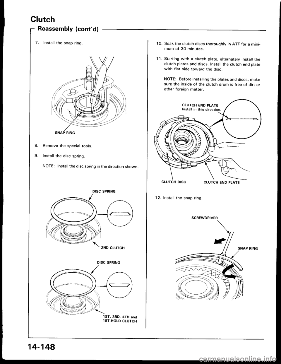
7. Install the snap ring.
Remove the special tools.
Install the disc spring.
NOTE: Installthe disc spring in the direction shown.
SNAP RING
DISC SPRING
.\
):ll
14-148
1ST, 3RD, 4TH andl ST.HOLD CLUTCH
1O. Soak the clutch discs thoroughly in ATF for a mini-mum of 30 minutes.
11. Starting with a clutch plate, alrernately install theclutch plates and discs. Install the clutch end plate
with flat side toward the disc.
NOTE: Before insralling the plates and discs, makesure the inside of the clutch drum is free ot dirt orother toreign matter.
CLUTCH END PLAT€Install in this direction
12. Install the snap ring.
SNAP RING
SCREWDRIVER
Page 540 of 1413
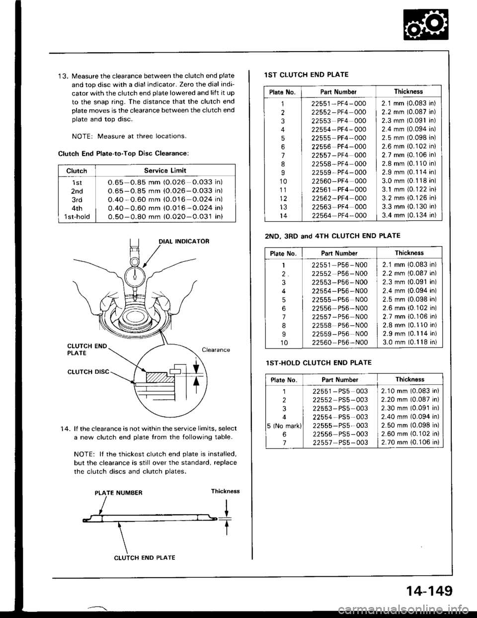
'13. Measure the clearance between the clutch end plate
and top disc with a dial indicator. Zero the dial indi-
cator with the clutch end plate lowered and lift it up
to the snap ring. The distance that the clutch end
plate moves is the clearance between the clutch end
plate and top disc.
NOTEr Measure at three locations.
Clutch End Plate-to-Too Disc Clearance:
1 4. lf the clearance is not within the service limits, select
a new clutch end plate lrom the following table.
NOTE: It the thickest clutch end plate is installed,
but the clearance is still over the standard, replace
the clutch discs and clutch Dlates.
Thickn€ss
ClulchService Limit
lst
2nd
3rd
4th
1st-hold
O.65 o.85 mm (O.026 O.O33 in)
O.65 - O.85 mm {O.026-O.O33 in)
O.4O-O.60 mm (0.O16 o.O24 in)
0.4O-0.60 mm (0.016-0.024 in)
0.50-0.8O mm {O.02O-0.031 in}
IAL INDICATOR
PLATE NUMBER
CLUTCH END PLATE
14-149
lST CLUTCH END PLATE
2ND- 3RD and 4TH CLUTCH END PLATE
lST.HOLD CLUTCH END PLATE
Plate No.Part NumberThickness
1
2
3
4
5
6
7
8
I
10
111)
IJ
14
22551-PF4-000
22552-PF4 000
22553 PF4 000
22554-PF4-OOO
22555 PF4-000
22556 PF4-000
22557 -PF4 000
22558-PF4 000
22559- PF4- 000
22560-PF4 000
22561 PF4-000
22562-PF4 000
22563-PF4 000
22564 PF4-OOO
2.1 mm 10.083 in)
2.2 mm (0.087 in)
2.3 mm (0.091 in)
2.4 mm (0.094 in)
2.5 mm (0.098 in)
2.6 mm {0.102 in}
2.7 mm i0.106 in)
2.8 mm (0.110 in)
2.9 mm (0.1 14 in)
3.0 mm (0.1 18 in)
3.1 mm (0.1 22 inl
3.2 mm {0.126 in}
3.3 mm (0.1 30 in)
3.4 mm (0.134 in)
Plate No.Part NumberThickness
1
2.
3
4
5
6
7
8
I
10
22551 P56,N00
22552-P56-N00
22553-P56-N00
22554- P56 -N00
22555-P56 N00
22556 Ps6- N00
22557 - P56 N00
22558 P56-N00
22559-P56 NOO
22560 P56-N00
2.1 mm (0.083 in)
2.2 mm (0.087 in)
2.3 mm (0.091 in)
2.4 mm (0.094 in)
2.5 mm (0.098 in)
2.6 mm {0.102 in)
2.7 mm {0.106 ini
2.8 mm (0.110 in)
2.9 mm (0.1 14 in)
3.0 mm (0.1 18 in)
Plare No.Part NumberThicknEss
1
2
3
4
5 (No mark)
6
7
22551-PS5 003
22552 PS5-003
22553-PS5 003
22554-PS5-003
22555-PS5-003
22556 PS5-003
22557 PS5-003
2.10 mm (0.083 in)
2.20 mm (0.087 in)
2.30 mm (0.09'1 in)
2.40 mm (0.094 in)
2.50 mm {0.098 in)
2.60 mm {0.102 in}
2.70 mm (0.106 in)
Page 550 of 1413
Transmission
Reassembly (cont'dl
SUB-SHAFT
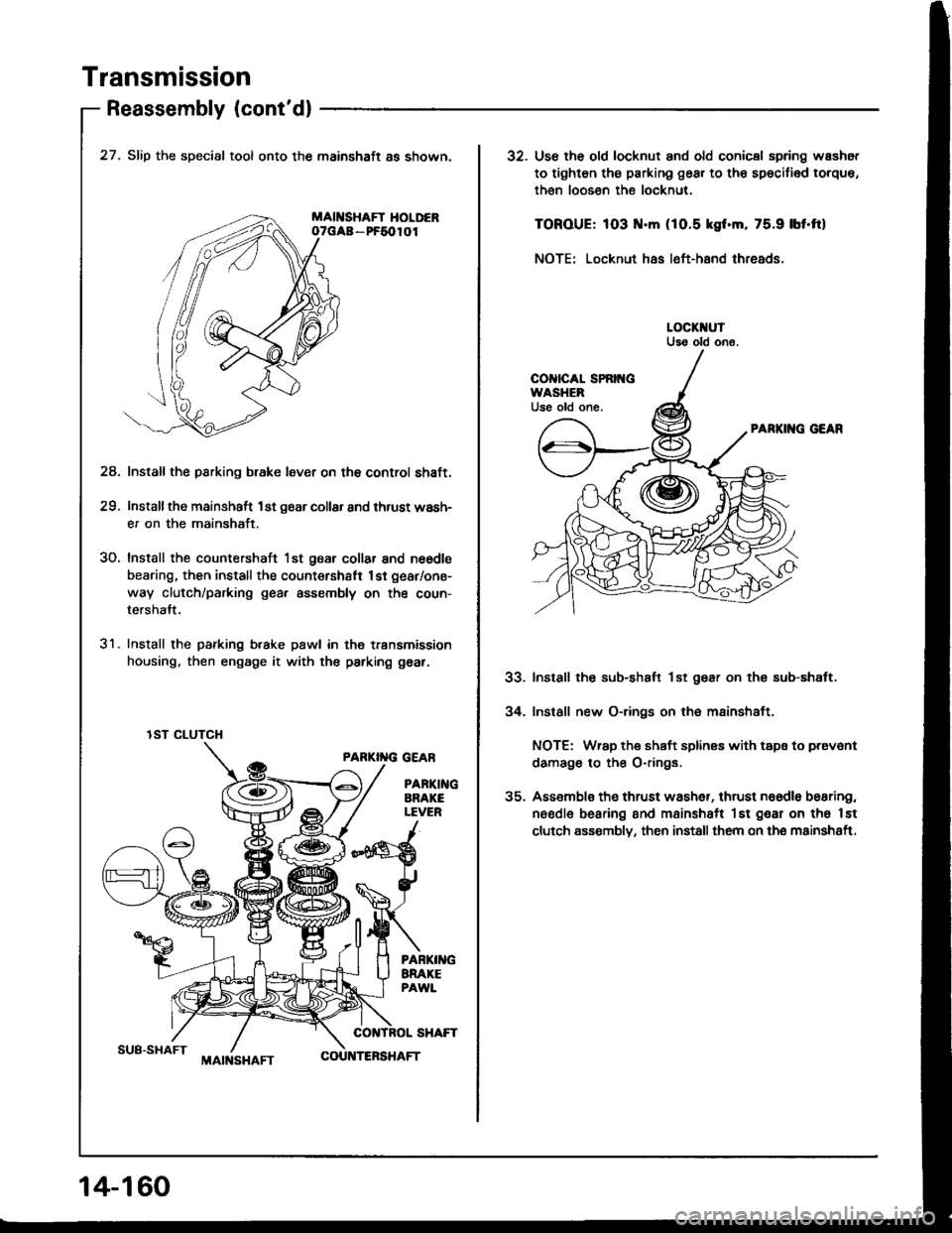
27. Slip the special tool onto the mainshaft as shown.
MAII{SHAFT HOLDERoTGAa - PF5010I
Install the parking b.ake lever on the control shaft.
Installthe mainshaft 1st g6ar collar and thrust wash-
er on the mainshaft.
Install the countershaft 1st gear collar and n6€dls
bearing, then install the count€rshatt 1st gear/one-
way clutch/parking gea, assembly on the coun-
tershalt.
Install the parking b.ake pawl in th€ transmission
housing, then engage it with the parking gear.
PARKI''IG GEAR
PARTI GARAKELEVER
24.
29.
30.
31.
lST CLUTCH
14-1 60
MAIt{SHAFTCOU TERSHAFT
32. Use th6 old locknut and old conicsl spring washot
to tighten th€ parking gear to th€ sp€cifi€d torque,
then loosen the locknut.
TOROUE: 103 .m (1O.5 kgf.m, 75.9 lbf'ftl
NOTE: Locknut has left-hand threads.
PARKII{G GEAR
Install the sub-shaft lst gear on thg sub-shaft.
Install new O-rings on the mainshaft.
NOTE: Wrap the shaft splines with tspa to prevont
damago to the O-rings.
Assemblo th€ thrust wash6r, thrust naedle bearing,
needle bearing and msinshsft lst gear on tho lst
clutch assombly, then install them on the mainshaft.
33.
34.
Page 572 of 1413
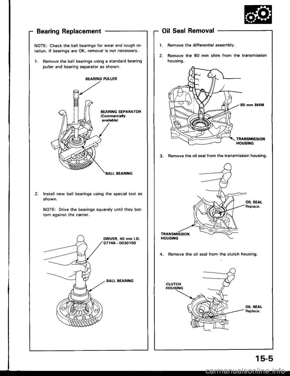
NOTE: Check the ball bearings for wear and rough ro-
tation. It bearings are OK, removal is not necessary.
1. Remove the ball bearings using a standatd bearing
puller and bearing separator as shown.
BEARING PULLEB
BALL BEARING
Install new ball bearings using the special tool as
snown.
NOTE: Drive the bearings squarely until they bot-
tom against the carrier.
DRIVER, 40 mm l.D.07746-0030100
BALL BEARING
Bearing ReplacementOil Seal Removal
1.Remove the ditterential assembly.
Remove the 8O mm shim from the transmission
housing.
80 mm SHIM
TRA[{SMtSStONHOUSING
3. Remove the oilseal from the t.ansmission housing.
4. Remove the oil seal from the clutch housing,
OIL SEALR€plac6.
15-5
Page 573 of 1413
Differential (81 881 engine)
Side Clearance Adjustment
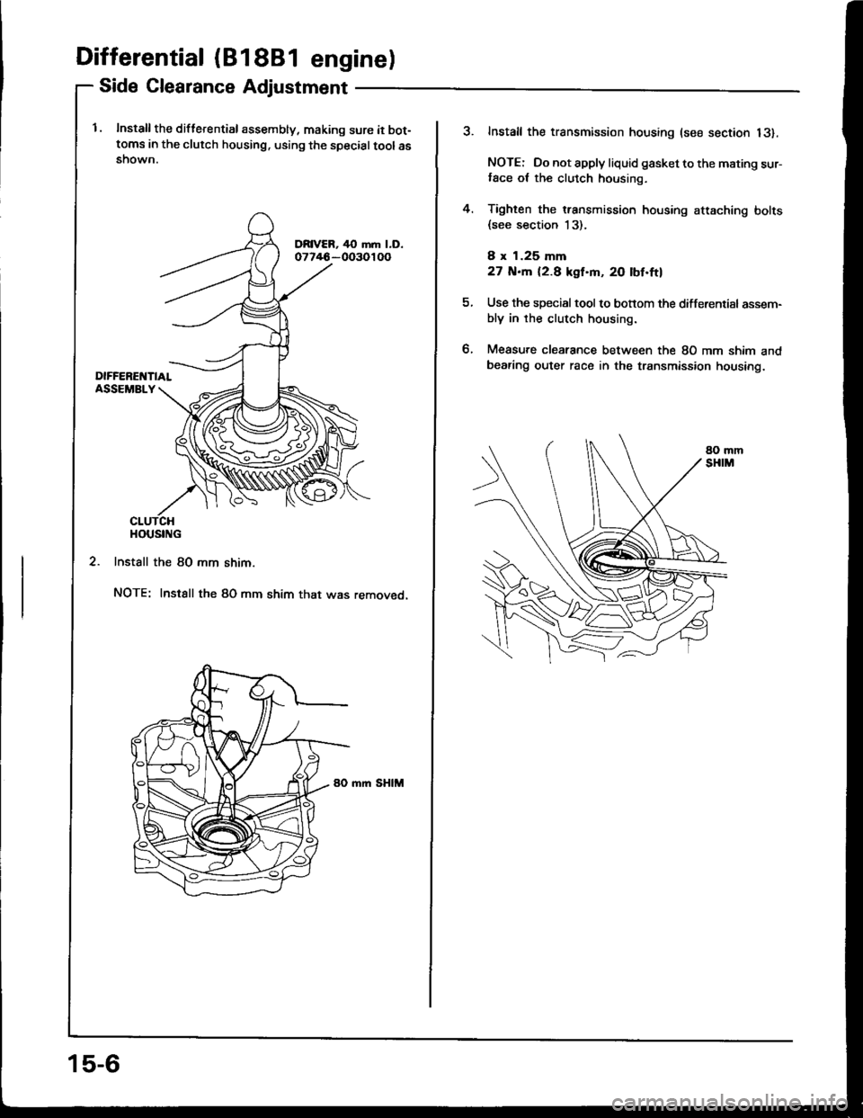
l. Install the diflerential assembly, making sure it bot-toms in the clutch housing. using the specialtoolasshown.
2. Install the 80 mm shim.
NOTE: Instsll the 80 mm shim that was removed.
mm SHIM
HOUSING
15-6
?Install the transmission housing (see section 13).
NOTE: Do not apply liquid gasket to the mating sur-,ace ot the clutch housing.
Tighten the transmission housing attaching bolts(see section 13).
8 x 1.25 mm
27 N.m 12.8 kgf'm, 20 lbf.ftl
Use the special tool to bonom the differential assem-bly in rhe clutch housing.
Measure clearance between the 80 mm shim andbearing outer race in the transmission housing.
4.
tt.
Page 575 of 1413
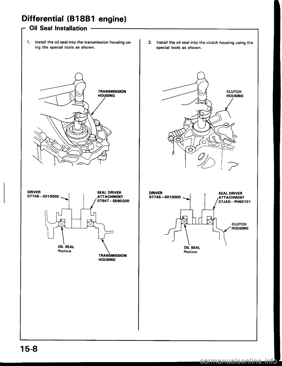
Differential (81 88l enginel
Oil Seal Installation
1. Install the oil seal into the t.ansmission housing us-
ing the special tools as shown
DRIVER07749-0010000
OIL SEALReplsce.
HOUSING
15-8
Install the oil seal into the clutch housing using the
soecial tools as shown.
DRIVER07749-0010000
OIL SEALReplace.
Page 580 of 1413
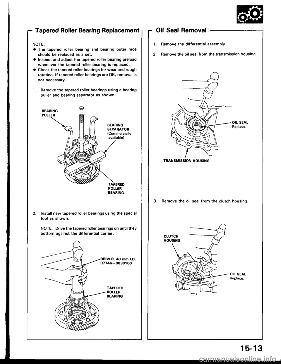
Tapered Roller Bearing Replacement
NOTE:
a The tapered roller bearing and bearing outer race
should be replaced as a set.
a Inspect and adjust the tapered roller bearing preload
whenevef the tapered rollef bearing is replaced.
a Check the tapered roller bearings tor wear and rough
rotation. lf tapered roller bearings are OK, removal is
not necessary.
1. Remove the tapered rolle. bearings using a bearing
puller and bearing separator as shown,
BEARING
BEARII{GSEPANATOR(Commercially
available)
Install new tapered roller bearings using the special
tool as shown.
NOTE: Drive the tapered roller bearings on until they
bottom against the differential carrier.
oilSealRemoval
1.Remove the differential assembly.
Remove the oil seal from the transmission housing.
3. Remove the oil seal from the clutch housino.
15-13