clutch HONDA INTEGRA 1994 4.G Workshop Manual
[x] Cancel search | Manufacturer: HONDA, Model Year: 1994, Model line: INTEGRA, Model: HONDA INTEGRA 1994 4.GPages: 1413, PDF Size: 37.94 MB
Page 1083 of 1413
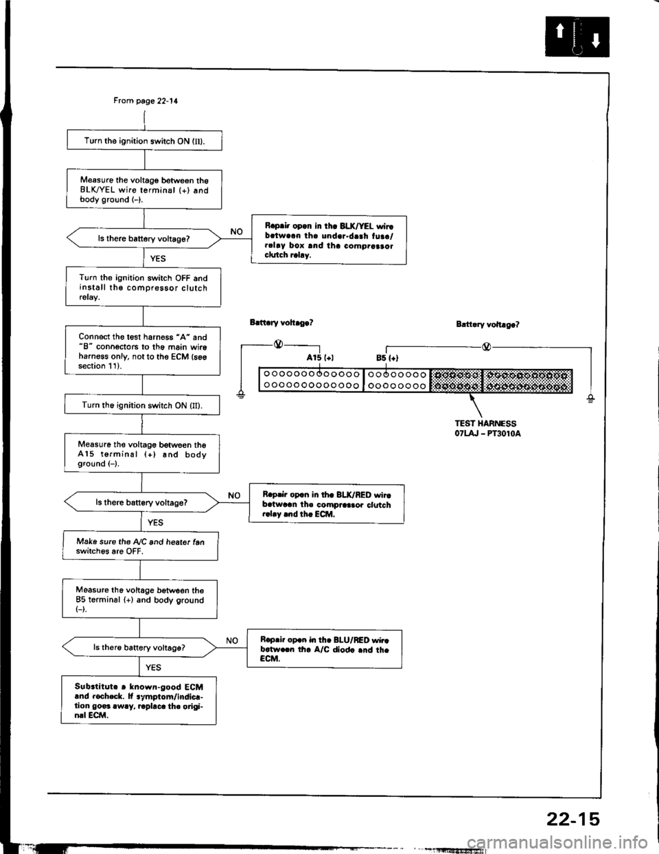
Frcm page 22-11
Bdt ry vohro.?
_@_____-l
Turn the ignition switch ON (lI).
M€asure the voltage betweon th6BLK/YEL wire terminsl {+) andbody ground (-).
R.p.i. opcn in th. 3LX/YEL wirrbalwarn tha undar.da3h tuaa/.clay box and iha como.aaao.clutch rahy.
ls there battery voltage?
Turn the ignition switch OFF andinstall the comprossor clutchrelay.
Connect the test harness "A" and"8" conoectors to th6 main wireharness only, not to the ECM (s6gsection 11).
Turn th6 ignition switch ON (II).
Measure the voltagG between theA15 terminal (+) and bodyground (-1.
R.prir op.n in th. BLK/RED wirtb.twran the compraa.or clotch..1.y .nd th. ECM.
Make sure the A/C and heate. tenswitch6s are OFF.
Measure tho voltage b€tween the85 terminsl (+) and body ground(-).
R.p.ir op.n in th. BI-U/RED wir.b.tw.rn th. A/C diod. .nd th.CCM.
Sub.titute r known-good ECMand rocheck. lt lymptom/indicr-tion go€3 rwry, rapbca th. origi-nrl ECM.
Blttary vohago?
r_--@_Bs {+)
TEST HARNESS07t4, - PT3010a
" , -1llltf,'tfrSfiiwiafi
22-15
Page 1085 of 1413
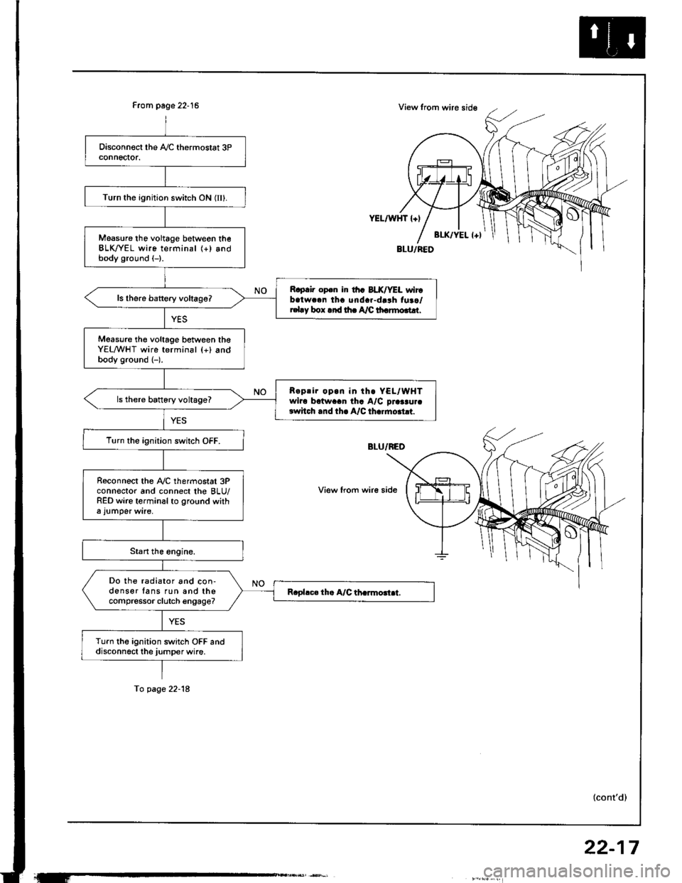
From page 22-15
Turn the ignition switch ON (IIl.
Measure tho voltage betweon theBLK/YEL wire terminal (+) andbody ground (-).
R.p.i. op.n ir th. BLX/YEL wirobatwc.n tha unda.-darh fuao/r.l.y box .rd rh. A/C th.rmo.t!r.
Measure th€ voltage between theYEL/WHT wire terminal {+} andbody ground (-).
R.prir op.n in th. YEL/WHTwiro bctwaan tha A/C praaau.crwhch .nd th. A/C th..mo.ht.
ls there battory voltage?
T!rn the ignition switch OFF.
R€connect the Ay'C thermostat 3Pconn€ctor and connect the BLU/RED wire terminal to ground witha l!mper wire,
Do the radiator and con-donser fans run and thecompressor clutch engage?
Turn the ignition switch OFF anddisconn6ct the jumper wire.
YEL/WHT l+l
View from wir€ side
To page 22-18
(cont'd)
22-17
Page 1087 of 1413
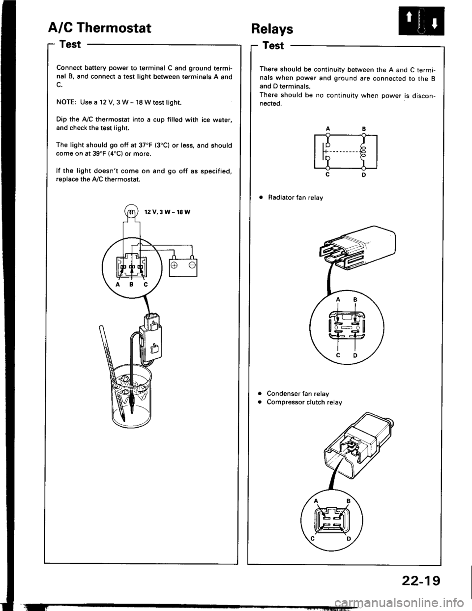
A/C Thermostat
Test
Connect battery power to terminal C and ground termi-
nal B, and connect a test light between terminals A and
NOTE: Use a 12 V, 3W- 18Wtest light.
Dip the A-/C thermostat into a cup filled with ice water,
and check the test light.
The light should go off at 37"F (3"C) or less. and should
come on at 39"F (4"C1 or more.
lf the light doesn't come on and go off as specified,
replace the Ay'C thermostat.
There should be continuity between the A and C term!nals when power and ground are connected to the Band D terminals.
There should be no continuity when power is discon-nected.
. Radiator fan relay
Condenser fan relay
Compressor clutch relay
Relays
a
a
,I Ir-b
InP.I I
12V.3W-18W
ABC
22-19
Page 1091 of 1413
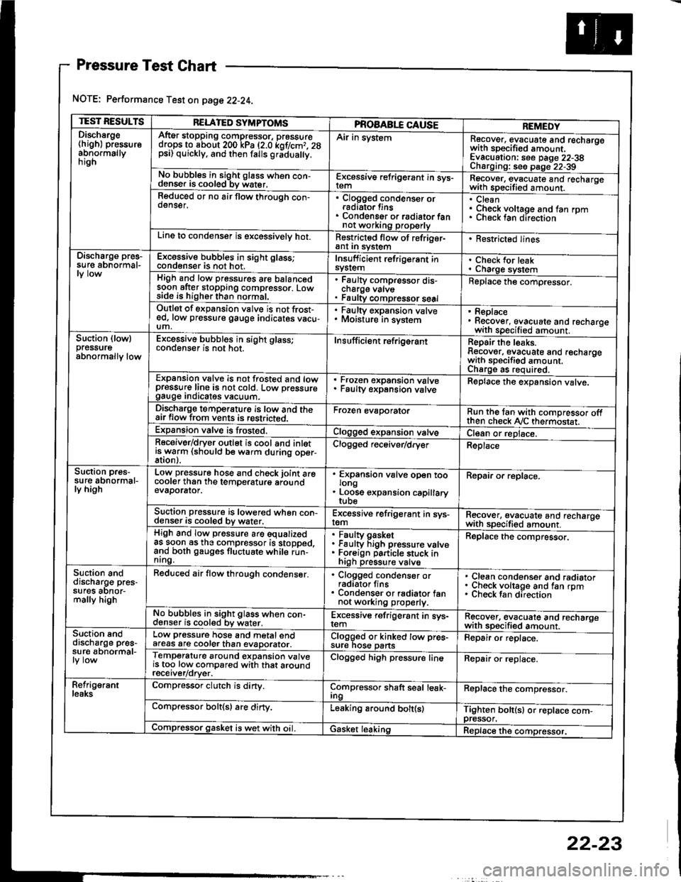
Pressure Test Chart
NOTE: Performance Test on page 22-24.
TEST RESULTSRELATED SYMPTOMSPROAABLE CAUSEREMEDYDischsrge(high) pressureabnormallynrgn
AftEr stopping compressor, pressuredrops to about 200 kPa (2.0 kof/cmr. 28psi) quickly, and then falls gr;dua y.
Air in systemRecover, evacuate and recharqowith sDecified amount. -
Evacuation: see Daqe 22-38Charoino: se6 D;op--2?-?qNo bubbles in sight g16ss when con-denser is cooled bv water.E-\cessive refrigerant in sys-Recover, evacuate and recharqewith specitied amount. -
Reduced or no air flow through con-oenser.Clogged condenser orradiato. finsCondenser o. radiator fannot working properly
CleanCheck voltage and fan rpmunecK lan ofeclton
Line to condenser is excessivelv hot.Restricted flow of refriger-ant In syslem. Restricted lines
Discharge pres-su re abnormal-Excossive bubbles in sight glass;condenser is not hot.Insuff icient refrigerant insyslemCheck for leakCharge systemHigh and low pressures are balancedsoon after stopping compressor. Lowside is higher than normal,
Faulty compressor dis-cnarge vaNsFaulty compressor seal
Replace the compressor.
Outlet of expansion vslve is not frost-ed, low pressure gauge indicates vacu-um,
. Faulty expansion valve. Moisture in sysiem. Replace. Recover, evacuate and recharoewith specified amount. -
Suction (lowlpressureabnormally low
Excessive bubbles in sight glass;conqenser rs not hot_Insuff icient ref rigerantReoair the leaks.Reaover, evacuate and recharoewith sDecifisd amount. -
Charqe as required.Expansion valve is not trosted and lowpressur€ line is not cold. Low pressuregauge Inorcates vacuum.
Frozen expansion valveFaulty expansion valveReplace the expansion valve.
Discharge temperaturg is low and theair flow from vents is restricted.Froren evaporatorRun the tan with comoressor oftthen check Ay'C thermostat.Expansion valve is frost€d.Clogged expansion valveCl€an or replace.Receiver/dryer outlet is cool and inletisrryarm (should be warm during oper-Clogged r€ceiver/dry€rReplace
Suction pres-su re abnormal-ly high
Low pressure hose and check joint arecooler than the temDeraturo aroundevaDorator.
'
ffin"nsion u"lu" oD"n too
. Loose expansion capillary
Repair or replace.
Suction pressure is lowered when con-denser is cooled by water,Excessive refrigerant in sys-remRecover, evacuate and recharqewith sDecifi€d amount. -
High and low pressure are equalizedas soon as the compressor is stopped,and both gauges fluctuate while run-nrng.
Faultv oasketFaulty Figh pressure valveForeign particle stuck inhigh pressure valve
Replace the compressor.
Suction anddischarg€ pres-sufes aonor-mally high
Reduced air flow through condenser.. Clogged condenser orradiator fins. Condenser or radiator fannot working properly.
Clean condenser and radiatorCheck voltage and fan rpmCheck fan direcrion
No bubbles in sight glass when con-cl€nser is cooled bv water.Excessive refrigerant in sys-remRgcover, €vacuate and recharoewith sp€cified amount.Suction snddischarge pres-su r€ abnormal-
Low pressure hose and metal endafeas are cooler than evaDorator.Clogged or kinked tow pre€-sure nos€ pansFepair or replace.
Temperature around expansion valveis too low compared with that aroundrecerver/orver.
Clogged high pressure lineRepair or replace.
Refrig€rantleaksCompressor clutch is dirty.Compressor shaft seal leak-IngReplace the comDressor.
Compressor bolt(s) are dirty.Leaking around bolt(s)Tighten bolt(sl or replace com-pressor.Compressor gasket is wet with oil. IGasket leakingReplace the compressor.
22-23
Page 1097 of 1413
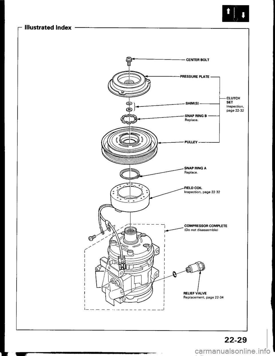
lllustrated lndex
CENTER BOLT
CLUTCHSETInspoc!on,page 22-32
SNAP RING AReplace.
-t COMPRESSOR COMPLETE
f-- lDo nor disassemble)
colLInspection, pag6 22 32
RELIEF VALVE
'-f
Replacement, page 22-34
22-29
Page 1098 of 1413
Compressor
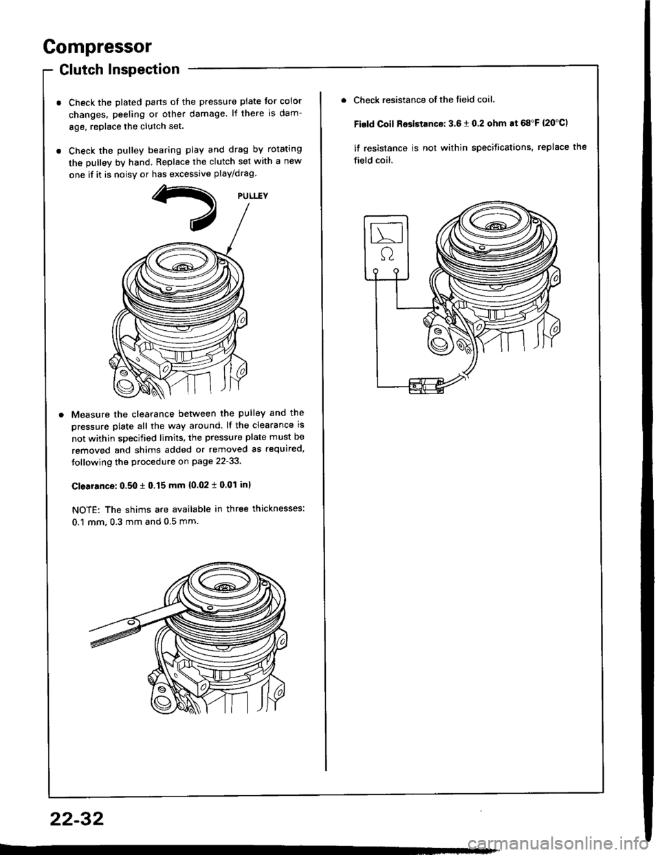
Glutch Inspection
Check the plated parts ot the pressure plate tor color
changes. peeling or other damage. lf there is dam-
8ge, replace the clutch set.
Check the pulley bearing play and drag by rotating
the pulley by hand. Replace the clutch set with a new
one if it is noisv or has excessive play/drag
Measure the clearance betlveen the pulley and the
pressure plate all the way around. lf the clearance is
not within specified limits, the pressure plate must be
removed and shims added or removed as required.
Jollowing the procedure on page 22-33.
Clearrnce: 0.50 t 0.15 mm {0.02 i 0.01 inl
NOTE: The shims are available in three thicknesses:
0.1 mm, 0.3 mm and 0.5 mm.
22-32
Check resistance of the tield coil.
Fisld Coil Rosistance: 3.6 t 0.2 ohm at 68"F {20'C)
lf resistance is not within specifications, replace the
field coil.
Page 1099 of 1413
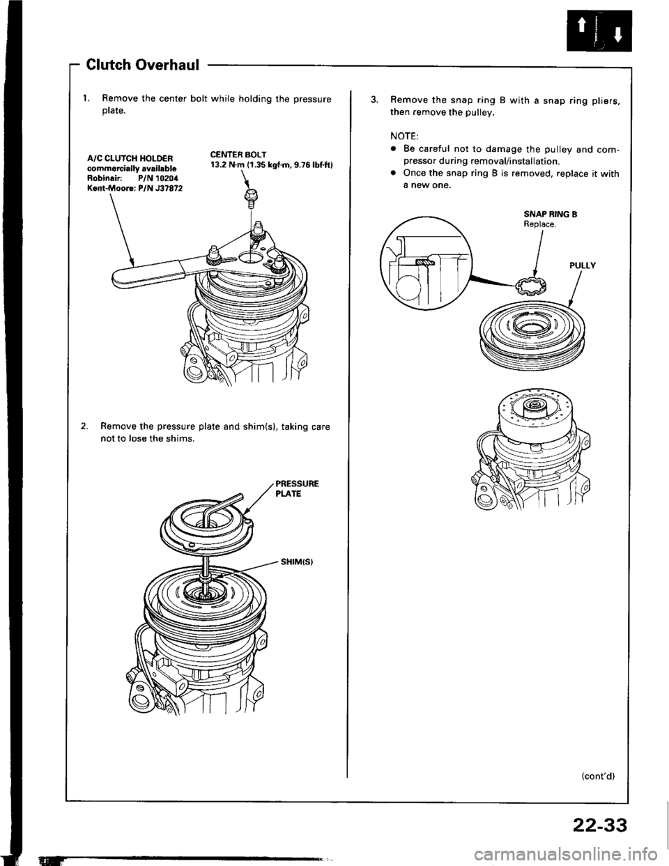
Glutch Overhaul
l. Remove the center bolt while holding the pressure
ptate.
A/C CLUTCH HOLDERcommorcially availsbleRobinair: P/N 10204Kont.Moore: P/N J37872
CENTER BOLT13.2 N.m (1.35 kgt.m,9.76 lbf.ftl
Remove the pressure plate and shim(s), taking care
not to lose the shims.
sHrM{s)
Remove the snap ring B with a snap ring pliers,
then remove the pulley.
NOTE:
. Be careful not to damage the pulley and com-presso. during removal/installation.
a Once the snap ring B is removed, replace it with
a new one,
SNAP RING BReplace.
(cont'd)
22-33
Page 1100 of 1413
and com
it with a
a
a
a
a
4t l\-N
r-
-l/
Compressor
Clutch Overhaul (cont'dl
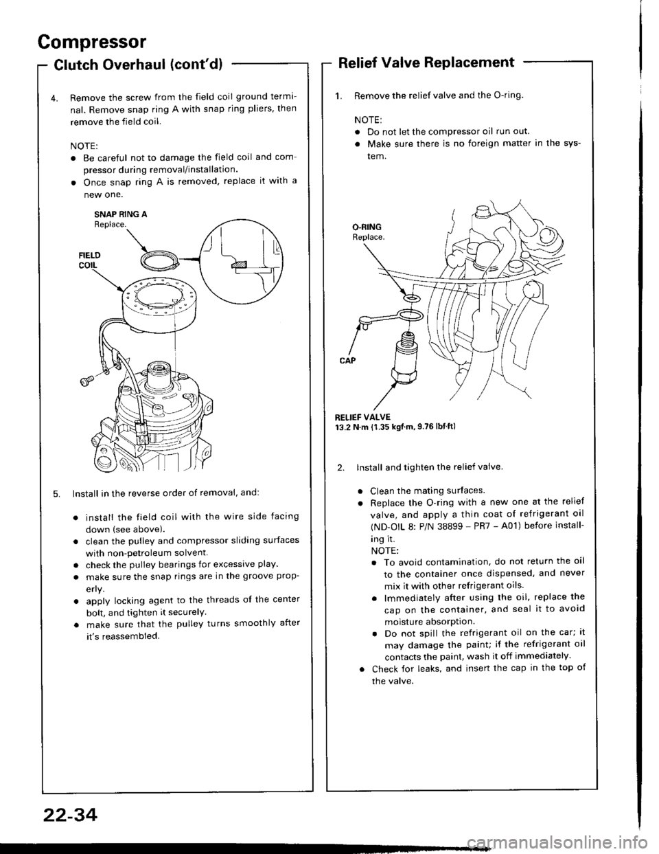
Remove the screw from the field coil ground terma-
nal. Remove snap ring A with snap rjng pliers, then
remove the field coil.
NOTE:
. Be careful not to damage the field coil
pressor during removal/installation.
. Once snap ring A is removed, replace
new one.
SNAP RING AReplace.
FIELDcorL
5. lnstall in the reverse order of removal, and:
install the field coil with the wire side facing
down (see above).
clean the pulley and compressor sliding surfaces
with non-petroleum solvent.
check the pulley bearings for excessive play.
make sure the snap rings are in the groove prop-
efly.
apply locking agent to the threads of the center
bolt, and tighten it securelY
make sure that the pulley turns smoothly after
it's reassembled.
1. Remove the relief valve and the O-ring.
NOTE:
. Do not let the compressor oil run out.
. Make sure there is no foreign matter in the sys-
tem.
RELIEF VALVE13.2 N.m {1.35 kgtm,9.76lbtftl
2. lnstall and tighten the relief valve.
Clean the mating surfaces.
Replace the O-ring with a new one at the relief
valve, and apply a thin coat of refrigerant oal
(ND-OIL 8: P/N 38899 - PR7 - A01) before install-
ing it.
NOTE:
. To avoid contamination, do not return the oil
to the container once dispensed, and never
mix it with other refrigerant oils.
. lmmediately after using the oil, replace the
cap on the container, and seal it to avoid
moisture absorption.
. Do not spill the refrigerant oil on the car; lt
may damage the painu if the refrigerant oil
contacts the paint, wash it off immediately.
Check for leaks, and insert the cap in the top of
the valve.
22-34
Page 1113 of 1413
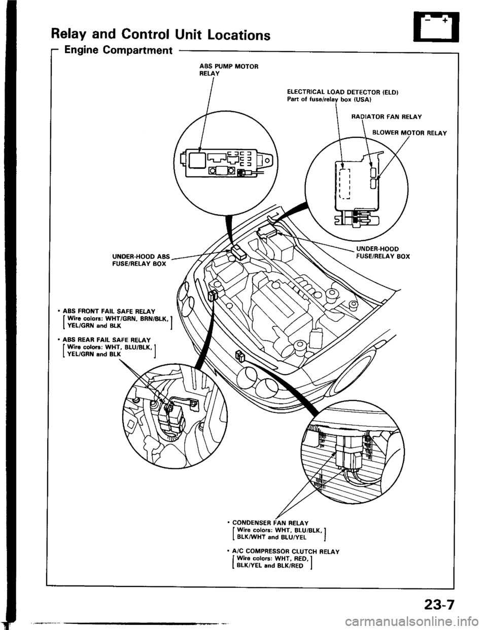
Relay and Control Unit Locations
Engine Compartment
ABS PUMP MOTORRELAY
ELECTRICAL LOAD DETECTOR (ELD)
UNDER.HOODFUSE/RELAY BOXUNOER-HOOD ABSFUSE/BELAY BOX
. ABS FRONT FAIL SAFE RELAY
I Wirc colors: WHT/GRN, BRN/BLK, IIYEL/GRN snd BLK I
. ABS REAR FAIL SAFE RELAY
I Wire colors: WHT, BLU/BLK, II YEL/GRN and BLK I
. CONDENSER FAN RELAY
I Wi]o colors: WHT, BLUi BLK, II BLKMHT and 8LU/YEL I
. A/C COMPRESSOR CLUTCH RELAY
I Wiro colors: WHT, RED, II BLK/YEL and BLK/RED I
23-7
Page 1120 of 1413
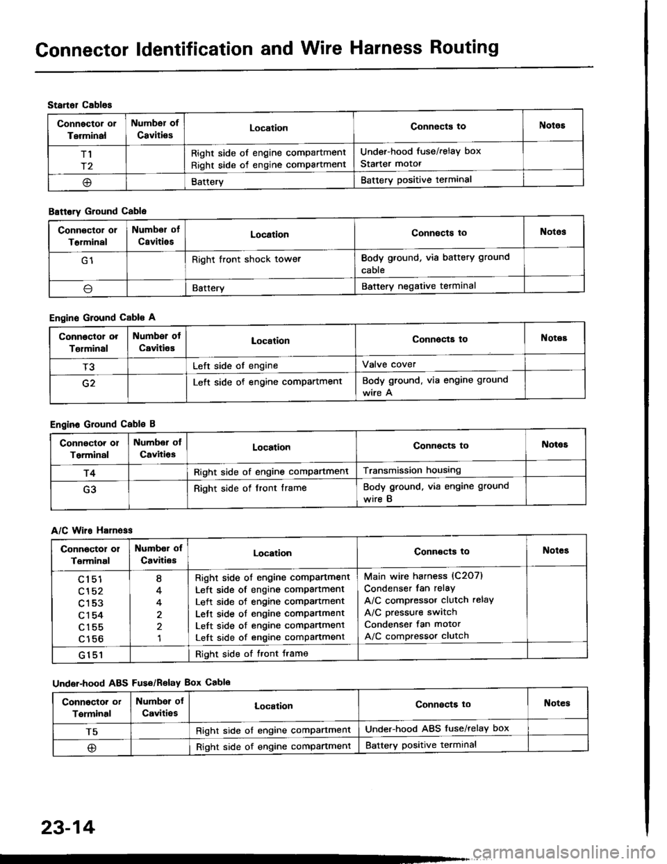
Gonnector ldentification and Wire Harness Routing
Startol cablos
Connector or
Terminal
Numbsr of
CavitiesLocationConnects toNotos
T1
r2
Right side of engine compartment
Right side of engine compartment
Under-hood fuse/relay box
Starter motor
@BatteryBattery positive terminal
B8ttory Ground Cable
Engine Ground Cable A
Engine Ground Cable B
A/C Wiro H81n6ss
Under-hood ABS Fus€/Relav Box Cablo
Conn€ctor or
T€rminal
Numbor of
CsvitiesLocationConnects toNotos
G1Right front shock towerBody ground, via battery ground
cable
\lBatteryBattery negative tetminal
Connoctor or
Tolminal
Number of
CavitiesLocationConnocta toNotes
T3Left side of engineValve cover
G2Left side of engine compartmentBody ground. via engine ground
wire A
Connoctor or
Torminal
Number ol
CavitiosLocationConnocts toNot€s
r4Right side of engine compartmentTransmission housing
G3Right side of front frameBody ground, via engine ground
wire B
Connoctor 01
Terminal
Numbor of
CavitiesLocationConnects toNotes
cl51
cl52
c153
c1 54
c155
c156
I
4
4
1
Right side ol engine comPartment
Left side of engine compartment
Left side of engine comPartment
Lett side ot engine compartment
Left side of engine comPanment
Left side of engine compartment
Main wire harness (C2O7)
Condenser fan relay
A/C compressor clutch relay
A/C pressure switch
Condenser fan motor
A/C compressor clutch
G151Right side of tront Jrame
Conngctor or
Terminal
Numbor ot
Caviti€sLocalionConnects loNotes
T5Right side of engine comPartmentUnder-hood ABS fuse/relay box
@Right side of engine compartmentBattery positive terminal
23-14