clutch HONDA INTEGRA 1994 4.G Workshop Manual
[x] Cancel search | Manufacturer: HONDA, Model Year: 1994, Model line: INTEGRA, Model: HONDA INTEGRA 1994 4.GPages: 1413, PDF Size: 37.94 MB
Page 1132 of 1413
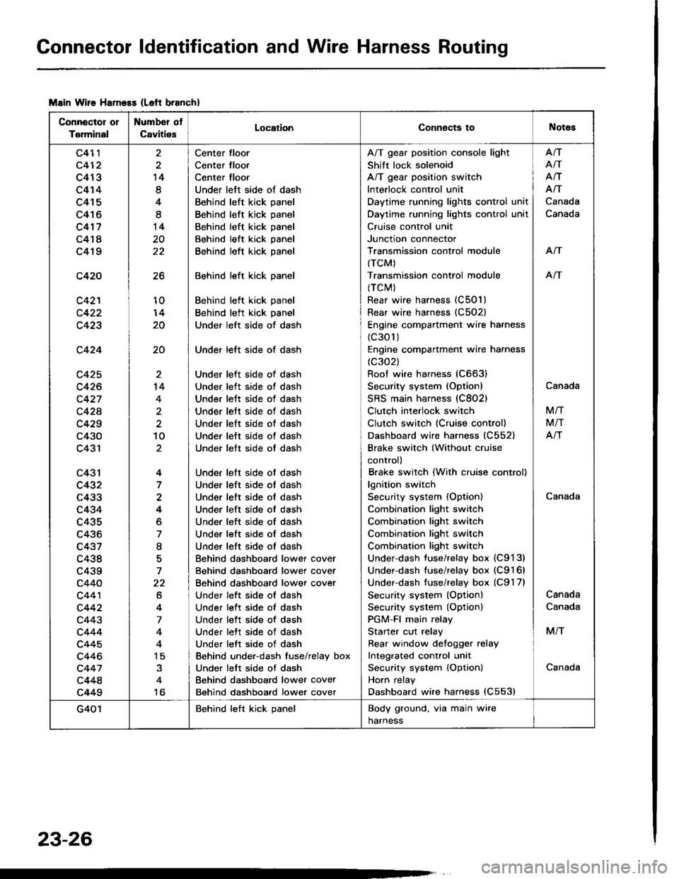
Connector ldentification and Wire Harness Routing
Msin Wiie Harness (Left branch)
Connector or
Terminal
Numbel ot
CavitiesLocationConnects toNotes
c411
c412
c413
c414
c415
c416
c4'17
c418
c419
c420
c42'l
c423
c424
c425
c426
c427
c42A
c429
c430
c431
c43l
c432
c433
c434
c435
c436
c437
c438
c439
c440
c44'l
c442
c443
c444
c445
c446
c447
c448
c449
26
10
20
20
14
8
4
I
14
20
22
't4
4
2
10
4
7
4
o
7
I
7
22
6
4
7
4
15
to
Center floor
Center floor
Center floor
Under left side ot dash
Behind left kick panel
Behind left kick panel
Behind left kick panel
Behind left kick panel
Behind left kick panel
Behind left kick panel
Behind left kick panel
Behind left kick panel
Under left side of dash
Under left side of dash
Under lett side of dash
Under left side ot dash
Under lett side of dash
Under lett side of dash
Under lett side of dash
Under lett side of dash
Under lett side ot dash
Under left side of dash
Under left side ol dash
Under left side of dash
Under left side of dash
Under left side of dash
Under left side of dash
Under left side of dash
Behind dashboard lower cover
Behind dashboard lower cover
Behind dashboard lower cover
Under left side of dash
Under left side of dash
Under left side of dash
Under lett side of dash
Under left side of dash
Behind under-dash fuse/relay box
Under left side ot dash
Behind dashboard lower cover
Behind dashboard lower cover
A/T gear position console light
Shift lock solenoid
A/T gear position switch
Interlock control unit
Daytime running lights control unit
Daytime running lights control unil
Cruise control unit
Junction connector
Transmission control module
(TCM)
Transmission controi module
{TCM)
Rear wire harness (C501)
Rear wire harness {C502)
Engine compartment wire harness
(c301)
Engine compartment wire harness
(c302)
Roof wire harness (C663)
Security system (Option)
SRS main harness (C802)
Clutch interlock switch
Clutch switch (Cruise control)
Dashboard wire harness (C552)
Brake switch (Without cruise
control)
Brake switch (With cruise control)
lgnition switch
Security system (Option)
Combination light switch
Combination light switch
Combination light switch
Combination light switch
Under-dash fuse/relay box {C9131
Under-dash fuse/relay box {C9161
Underdash tuse/relay box (C9'l 7l
Security system (Option)
Security system {Option)
PGM-FI main relay
Starter cut relay
Rear window defoqger relay
Integrated cont.ol unit
Security system {Option)
Horn relay
Dashboard wire harness (C553)
Afi
AiT
Afi
Afi
Canada
Canada
Arf
An
Canada
Canada
M/T
M/T
Atr
Canada
Canada
M/T
Canada
G401Behind left kick panelBody ground, via main wire
harness
23-26
Page 1158 of 1413
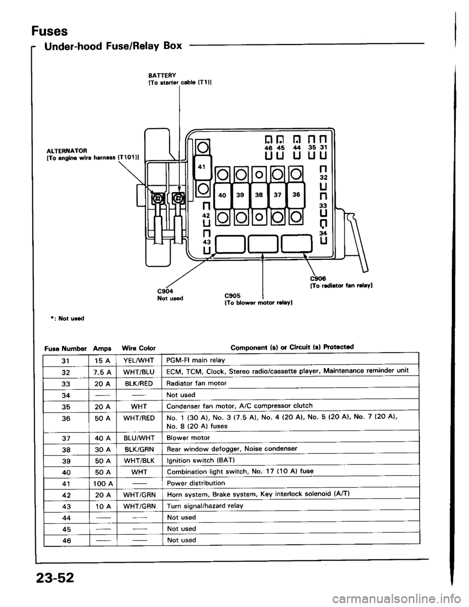
Fuses
Under-hood Fuse/Relay Box
ALTERI{ATOR
fTo .ngino wlto hsrno$ {Tlolll
Not usod
r: l\lot u3.d
umborAmpsColor
nF n nn46 45 /t4 35 3l
UU U UU
n32
U
n
33
U
r:rg
U
n
42
U
n43
U
[To rldidor hn r.l.Yl
Componon! (sl 01 Clrcuit 13) Protoqtod
3115 AYEL/WHTPGM-Fl main relay
327.5 AWHT/BLUECM, TCM. Clock, Stereo radio/cassette plsyer, Maintenance reminder unit
a2204BLK/REDRadiator Jan motor
34Not used
35204WHTCondenser fan motor, A/C compressor clutch
50AWHT/REDNo. I {3O A), No. 3 (7.5 A). No. 4l2O Al, No 5 (2O A), No. 7 (2O A),
No. I (20 A) fuses
3740ABLU/lVHTBlower motor
3830ABLK/GRNRear window defogger, Noise condenser
?q50AWHT/BLKlgnition switch {BAT}
4050AWHTCombination light switch, No. 17 (1O Al fuse
41100 APower distribution
4220AWHT/GRNHorn system, Brake system, Key interlock solenoid (Aff)
4310 AWHT/GRNTurn signal/hazard.elay
44Not used
45Not used
46Not used
23-52
Page 1163 of 1413
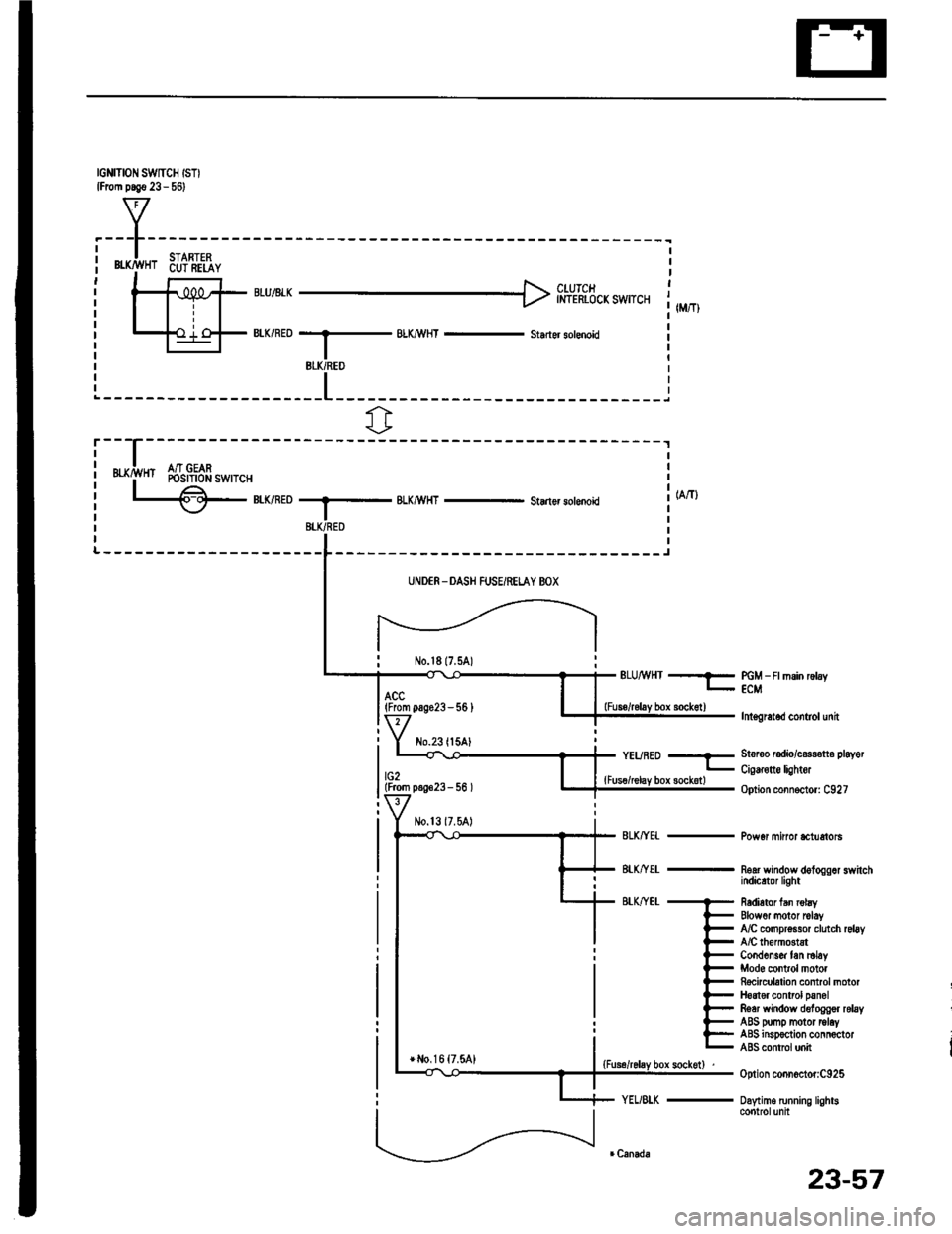
IGNITION SWTCH ISTIlFrom p.!€ 23 - 561
f7
I.---F-------lI-lSTARTFPi Bffi,!'HT 6u?'ili,iY i| -' r r l clurcr It-11iPt ;rui8rr H inl-rhicicxswrcr 1,,,,,,Itill-+{ .'.i o-F BIK/RED --.5 BLX/!\,HT - st.der sotenoid il-l I r
BLK/REO
fr
r---
uxrivn Sr$!gfr*,r.,
L€-eumoBLKMHT - Starlsr solenoki
-------J
UNDER -DASH FUSEiRELAY BOX
No.l817.5A)ELUMHT --?- PGM _ Ft msin rctay- ECM
lnt€gretod control unit
St6r6o radio/c$r€tt6 playot
Cig€rone lightor
Option connoctor: C927
Pow6r minor *tuetols
noar wandow dologgor switchindicrtor light
R6dietor fan robyElowor motor rclayfuC compr$sor clutch rsl6yA/C lhomGtstCond6ns& tan ml6yMod6 control motorRocicubtion control motorH6at€r control panolRear window deloggor relayABS pomp motor tolayABS insp€ction connoctorABS contrcl unit
Option connoctor:C925
Daytime running lightscontrolunit
(From pag623-56 )
No.23ll5AlYEURED --E
lG2lFrom p.!623- 56 ){Fus€/relay box sockotl
+ l,lo,16 {7.5A1
23-57
Page 1174 of 1413
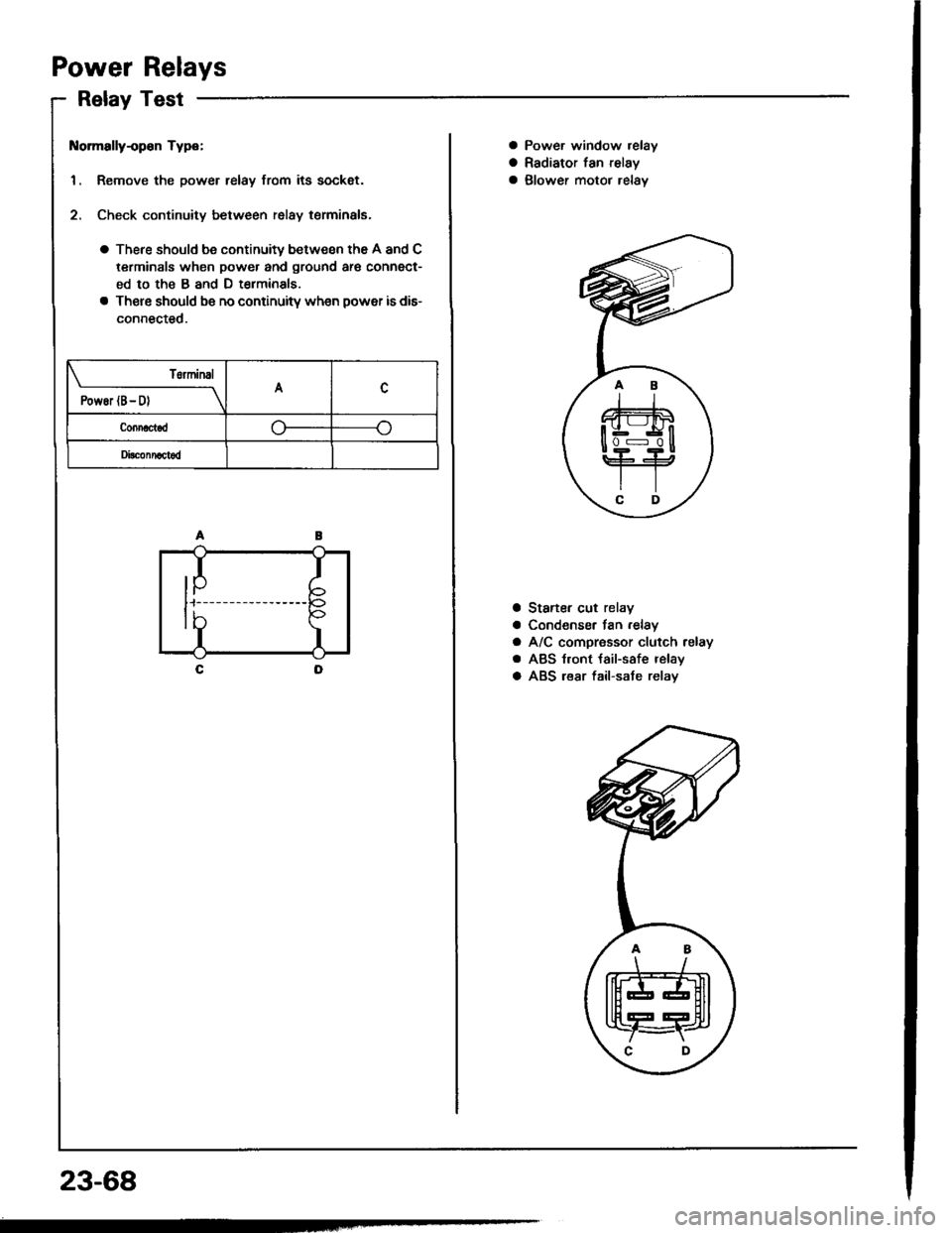
Power Relays
Relay Test
t{ormally-op€n Type:
1. Remove the power relay from its sockat.
2. Check continuity between relay terminals.
a There should be continuity between the A and C
terminals when power and ground ar€ connect-
ed to the B and D t€rminals
a There should be no continuitv wh€n power is dis-
connected.
T6rminal
PowEr (B- D)A
Connactod
Di!c!nnact6d
IP
I
I
tb
23-68
a Power window relay
a Radiator fan relay
a glower motor relav
a Staner cut relay
a Condenser fan .elay
a A/C compressor clutch relay
a ABS t.ont {ail-safe relay
a ABS lear fail-sate relav
.AB
\/
tffit
t[fT4r
\C D,
Page 1179 of 1413
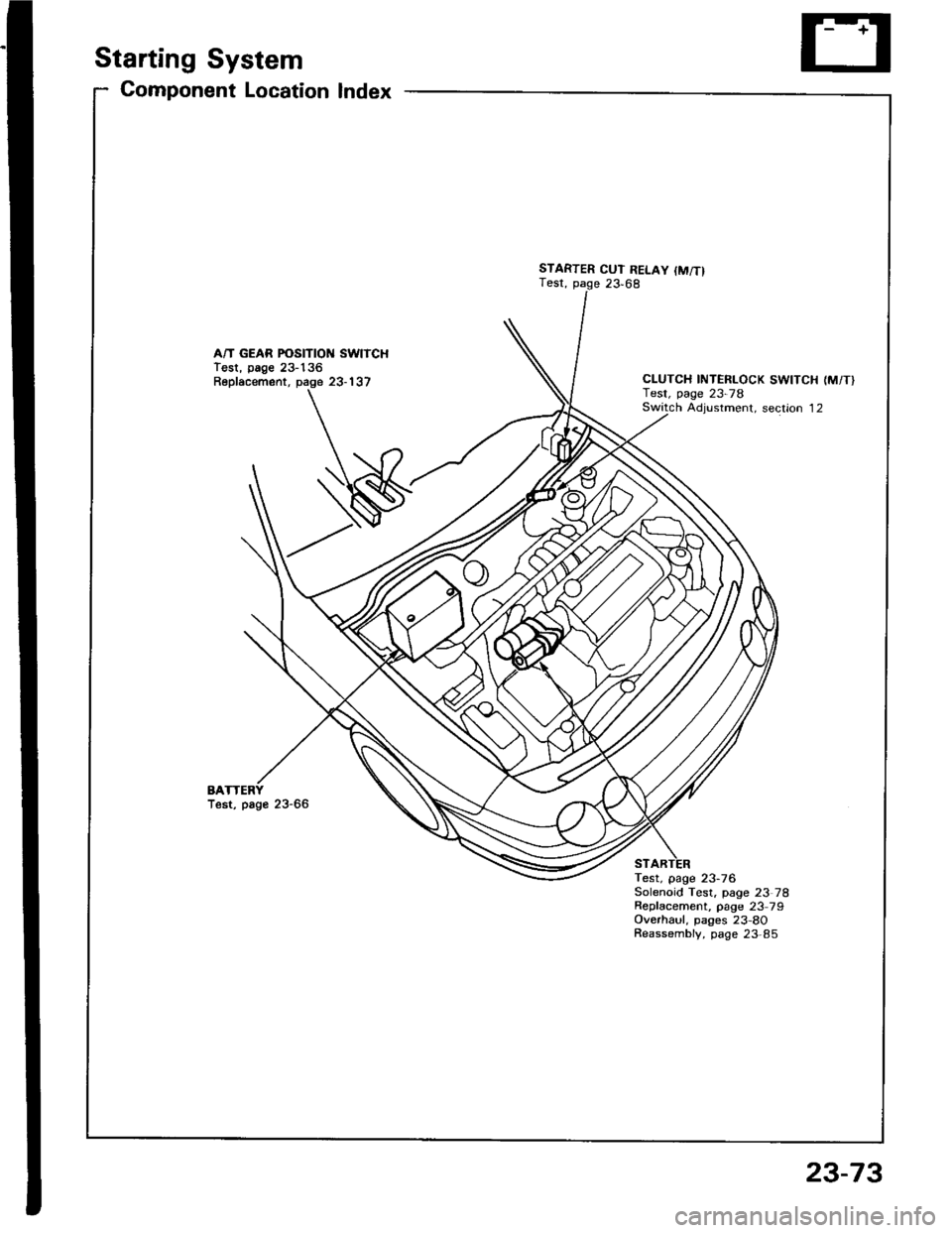
Starting System
Gomponent Location Index
A/T GEAR POSITION SWITCHTest, page 23-136Replacement, page 23-137
BATest, page 23-66
STARTER CUT RELAY {M/T}Test, page 23,68
CLUTCH INTERLOCK SWITCH (M/T}Test, page 23-78Switch Adiustment. section 12
Test, page 23-76Solenoid Test, page 23 78Repfacement, page 23 79Overhaul, pages 23-8OReassembly, page 23,85
23-73
Page 1182 of 1413
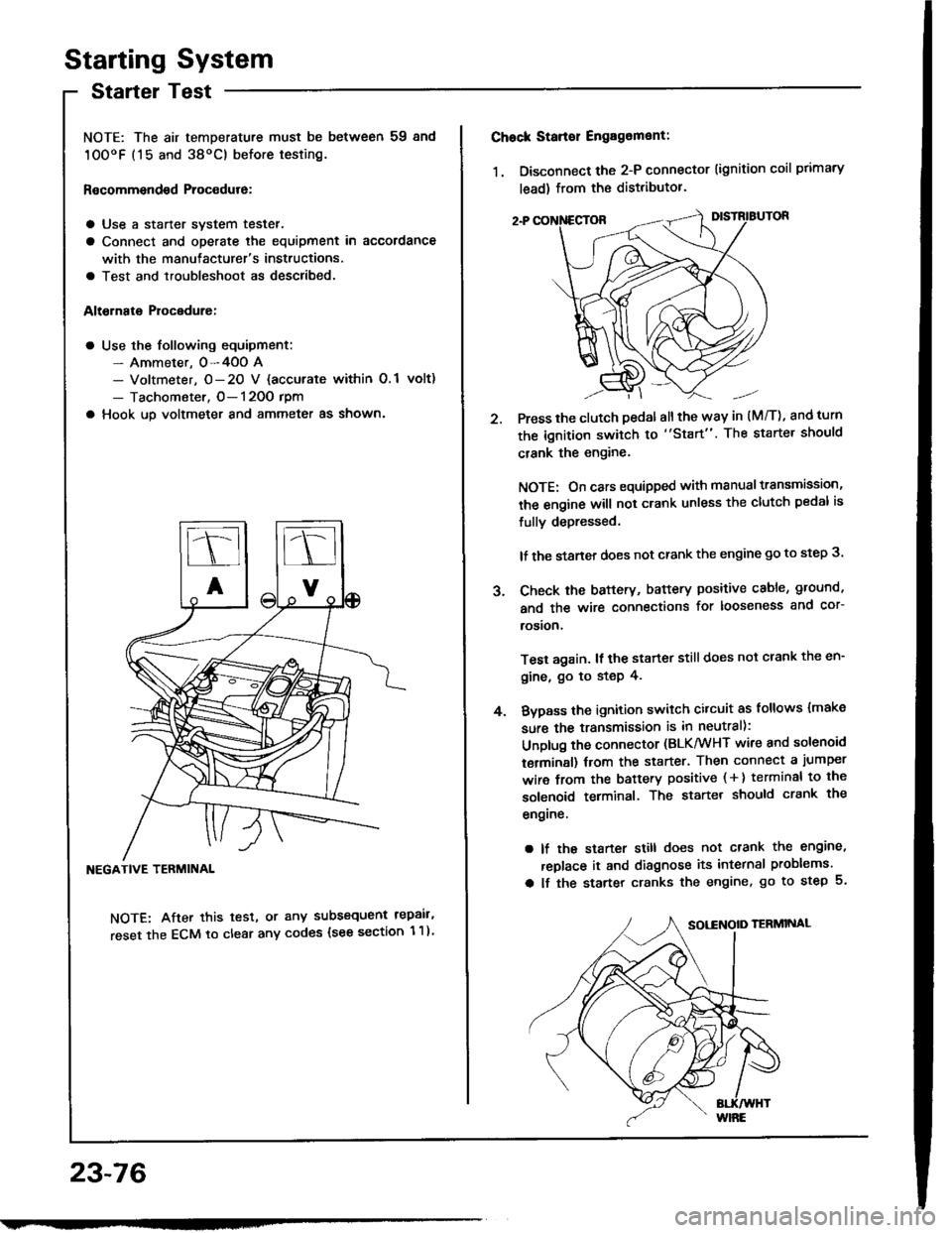
Starting System
Startel Test
NOTE: The air temDerature must be between 59 8nd
10OoF (15 and 38oC) before testing.
Recommendsd Procodure:
a Use a staner svstem tester.
a Connect and operate the equipment in accordance
with the manutacturer's instructions.
a Test and troubleshoot as described.
Altohato Procedure:
a Use the following equipment:- Ammeter. 0-4OO A- Voltmeter, O- 20 V {accurate within 0.1 volt)
- Tachometer, O- 120O rpm
a Hook up voltmeter and ammeter as shown'
NEGATIVE TERMINAL
NOTE: After this test, or any subsequent repair,
reset the ECM to clear any codes (see section 1 1)
23-76
2.
Chock Stan€r Engag6ment:
1. Disconnect the 2-P connector (ignition coil primary
lead) from the distributor.
Press the clutch pedal allthe way in (M/T), and turn
the ignition switch to "Start". The starter should
crank the engine.
NOTE: On cars equipped with manual transmission,
the engine will not crank unless the clutch pedal is
fully depressed.
lf the staner does not crank the engine go to step 3.
Check the baftery, battery positive cable, ground,
and the wire connections for looseness and cor-
rosion,
Test again. lf the starter still does not crank the en-
gine, go to step 4.
Bvpass the ignition switch citcuit as follows {make
sure the transmission is in neutral):
Unplug the connector (BLK/WHT wire and solenoid
terminsl) trom the starter. Then connect a jumper
wire from the battery positive ( + ) terminal to the
solenoid terminal. The starter should crank the
engrne.
a lf the starter still does not crank the engine,
replace it and diagnose its internal problems.
a lf the starter cranks the engine, go to step 5.
J.
4.
Page 1183 of 1413
5. Check lor 8n op€n in the BLKMHT wire circuit be-
tween the staner and ignition switch, and con-
nectors.
6. Check the ignition switch (see page 23-70).
7, On cars with automatic transmission, check the A/Tgear position switch (neutral position switchl and
connector. On cars with manualtransmission, check
the staner cut relay, clutch interlock switch, and
connectors.
NOTE: Check the No. 39 (5O A) fuse in the under-hood
fuse/relay box for the starter cut relay.
Check tor Woar and Damago:
The starter should crank the engine smoothly and stead-
ily. lf th€ startsr engages, but cranks the engine errati-
cally, remove it. Inspect the starter, drive gear, and
flywheel ring gesr for damage.
a Check the drive gear overunning clutch for binding
or slipping when the armature is rotated with the drivegear held. Replace the gesrs if damaged.
Check Cranking Voltago 8nd Current Draw:
Cranking voltage should be no less than 8.O volts.
Current draw should be no more than 360 amperes.
lf cranking voltag€ is too low, or current draw too high,
check for:
a Fully charged battery
a Open circuit in starter armature commutatot segments
a Starter armature dragging
a Shoned armature winding
a Excessive drag in engine
Chack Cranking rpm:
Engine spsod during cranking should be above 1O0 rpm.
lf spe6d is too low, ch€ck for:
a Loose battsry or starter teminals
a Excessively worn starter brushes
a Open circuit in commutator segments
a Dirty or damaged helical spline or drive gear
a Defective drive gear overrunning clutch
Chock StErtor Disongagomoni:
Press the clutch pedal allth€ way in (M/T), turn the ioni-
tion switch to "lll" and rolease to "11".
The starter drive gear should disengage from the tlywheel
ring gear. When you rolease the key.
lf the drive gear hangs up on th€ flywheel ring gear, check
for:
a Solenoid plunger and switch malfunction
a Dirty drive gear assembly or damaged overrunning
clutch
23-77
Page 1184 of 1413
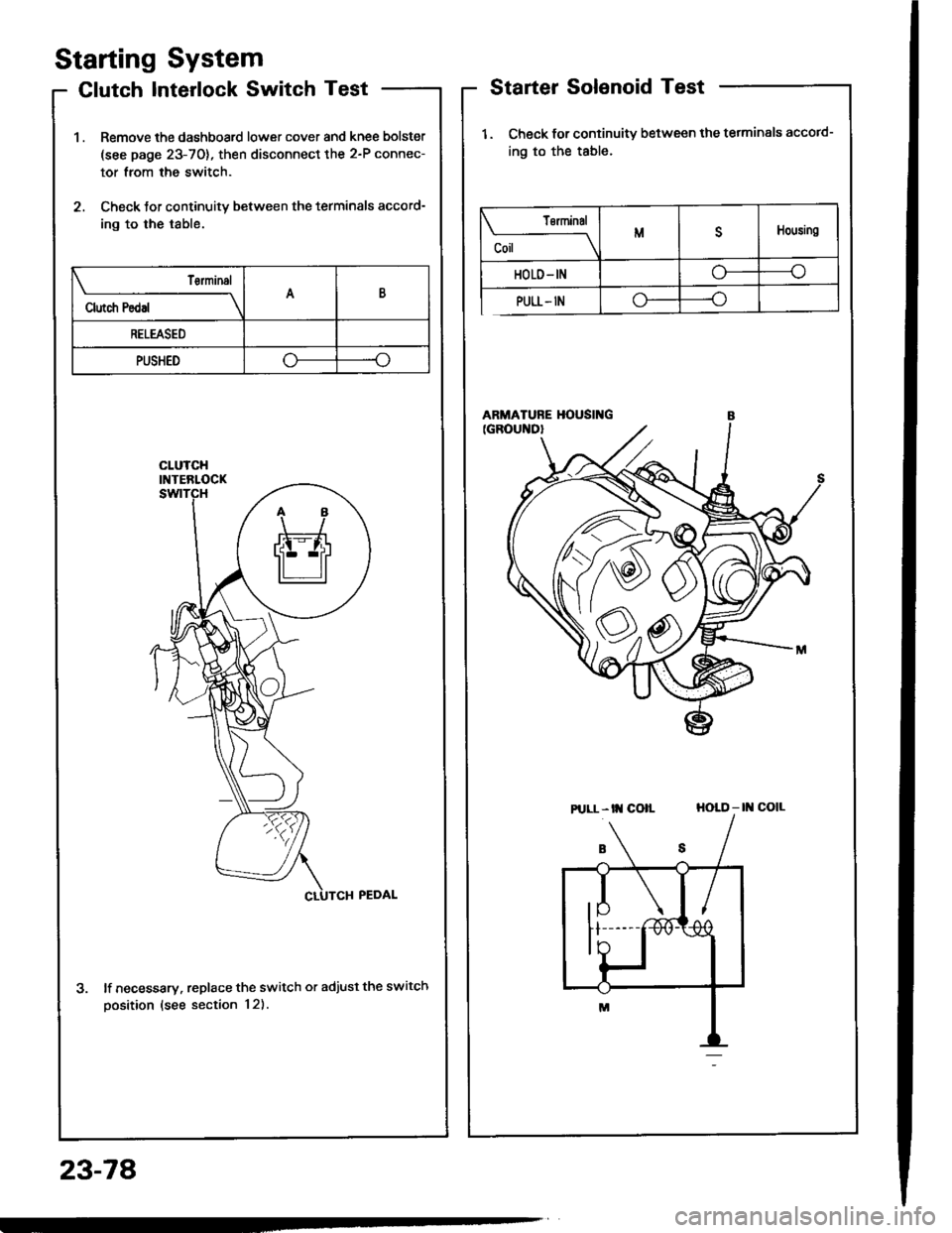
Starting System
Clutch Interlock Switch Test
1 . Remove the dashboard lower cover and knee bolster
(see page 23-70), then disconnect the 2-P connec-
tor from the switch.
2. Check tor continuity between the terminals accord-
ing to the table.
lf necessary. replace the switch or adjust the switch
oosition (see section 12).
Starter Solenoid Test
1. Check for continuitv between the tetminals accotd-
ing to the table.
HOLD - |l{ COIL
23-78
Tsrminal
CoilMDHousing
HOLD- INo----c
PULL- INo----.oClutch Pedal
T€rminalAB
RELEASED
PUSHEDoo
Pt LL- tt{ coll
Page 1186 of 1413
![HONDA INTEGRA 1994 4.G Workshop Manual Starting
Startel
System
Overhaul
from clutch side.
-s@]
MOLYBDENUMDISULFIDE
CAUTION: Disconnecl th€ battery n€gative cable befole
lomoving the startet.
NOTE: The original radio has a coded theft p HONDA INTEGRA 1994 4.G Workshop Manual Starting
Startel
System
Overhaul
from clutch side.
-s@]
MOLYBDENUMDISULFIDE
CAUTION: Disconnecl th€ battery n€gative cable befole
lomoving the startet.
NOTE: The original radio has a coded theft p](/img/13/6067/w960_6067-1185.png)
Starting
Startel
System
Overhaul
from clutch side.
-s@]
MOLYBDENUMDISULFIDE
CAUTION: Disconnecl th€ battery n€gative cable befole
lomoving the startet.
NOTE: The original radio has a coded theft protection
citcuit. Be sure to get the customer's code number before
- disconnecting the batterY.- removing the No.3 2 (7.5 A) fuse from the under-hood
fuse/relay box.- removing the tadio.
Atter service, reconnect power to the radio and turn at
on. When the word "CODE" is displayed, enter the cus-
tomer's 5-digit code to restore radio operation.
tr./.' BRUSH HOLDERTest, page 23-8'l
ERUSH
COVER
I
6
OVERRUNNING CLUTCH ASSEMBLYInspection, page 23_84
SOLENOIDPLUNGERInspection, page 23-85
BRUSH HOLOER
ARMATURE
STARTERSOLENOIDTest, page 23-78
PINION GEAR IDLER GEAR
Inspection, page 23-11
IDLER GEAR
I
@*
SOLENOID HOUSING
HARNESS BRACKET
STEEL BALL
install steel ball
lnspection and Test,page 23-82
ROLLER BEARINGSand CAGEPrevenl rollers trom being scattered and lost.
MOLYBDENUM DISULFIDE
_R1
MOLYADENUMDISULFIDE
23-80
ENO COVER
ARMATURE
GEAR HOUSING
Page 1190 of 1413
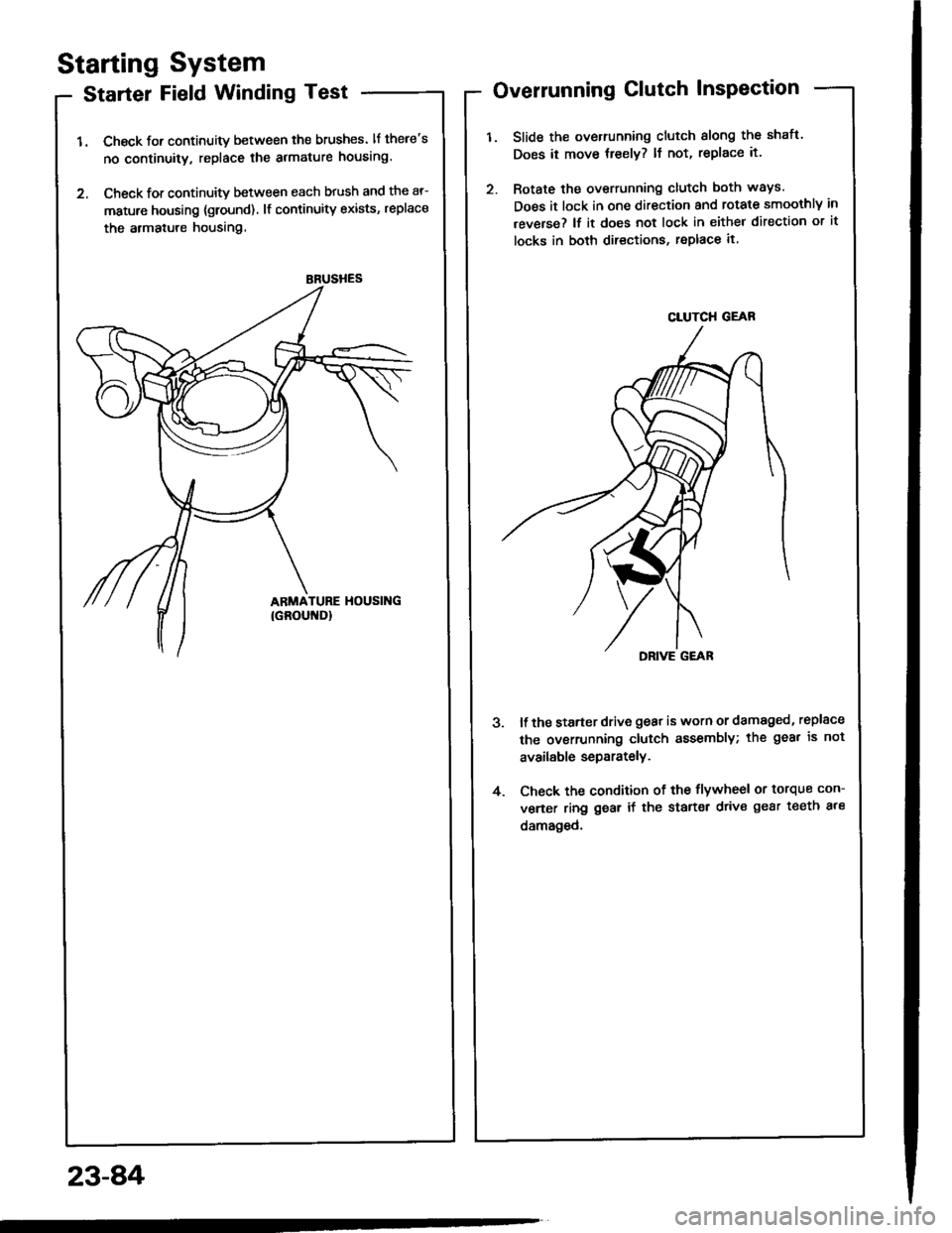
BRUSHES
Starting System
Starter Field Winding Test
1. Check for continuity between the brushes. lf there's
no continuity, replace the armature housing.
2. Check for continuity between each brush and the ar-
mature housing {ground) lf continuity exists, replace
the armatule housing.
Overrunning Clutch InsPection
Slide the overrunning clutch slong the shatt.
Does it move treely? ll not, replace it.
Rotate the overrunning clutch both ways.
Does it lock in one direction and rotate smoothly in
reverse? lf it does not lock in either direction or it
locks in both directions, replace it.
DRIVE G€AR
ll the starter drive gear is worn or damaged, replsce
the ovsrrunning clutch assembly; the gea. is not
available separately.
Check the condition of the flywheel or torque con-
verter ring gear if the starter drive gear teeth ale
damaged.
4.
23-8,4
CLUTCH GEAR