electric load detector HONDA INTEGRA 1994 4.G Workshop Manual
[x] Cancel search | Manufacturer: HONDA, Model Year: 1994, Model line: INTEGRA, Model: HONDA INTEGRA 1994 4.GPages: 1413, PDF Size: 37.94 MB
Page 197 of 1413
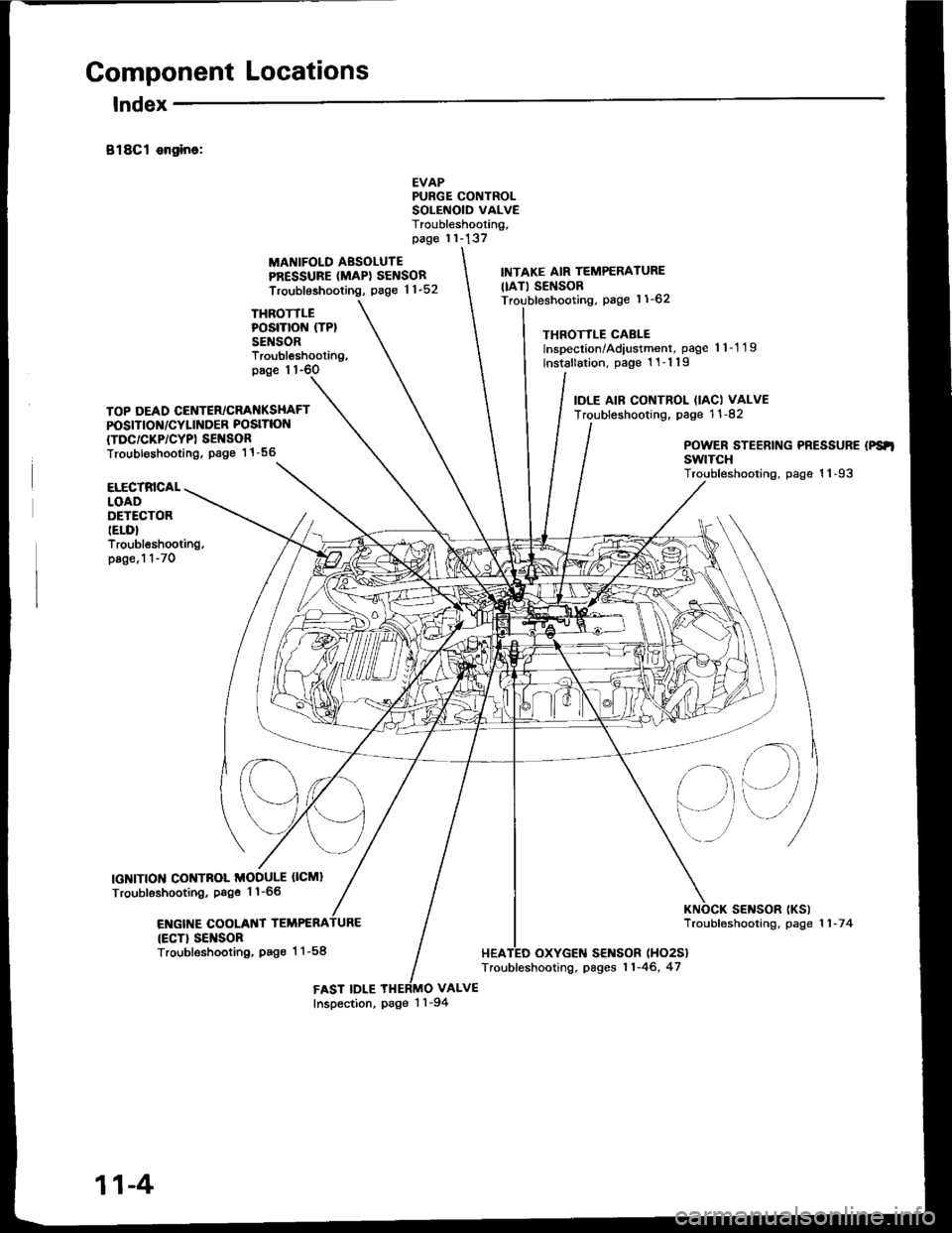
Component Locations
lndex
B18Cl ongino:
THROTTLEPOSITION (TP}
SENSOR
MANIFOLD AESOLUTEPRESSURE (MAPI SENSOR
Troubleshooting, page 1 1-52
EVAPPURGE CONTROLSOLEiIOID VALVETroubleshooting,page 11-137
VALVE
INTAKE AIR TEMPERATURE
IIAT) SENSORpage 11-62
THROTTLE CABLEInspection/Adiustment, page 'l 1-1 19
lnstallation, page 1 1-1 19
IOLE AIF CONTROL (IACI VALVETroubleshooting. page 1 1 -82
Troubleshooting,page 1 1-6O
TOP DEAD CENTER/CRANKSHAFTPOSITION/CYLINDER POSITION
{TDC/CKP/CYPI SEI{SORTroubl€shooting. Page 1 1 -56POWER STEERING PRESSURE (PS'I
swtTcHTroubleshooting, page 1 1-93ELECTRICALLOADDETECTORIELD}Troubleshooting,page.1 1-70
IGNITION CONTNOL MODULE OCMI
Troubleshooting, Psge 1'l-66
ENGIT{E COOLANT TEMPERA
{ECT} SEI{SORTroubleshooting, Pag€ 1 1-58
sElrlsoR tKslTroubfeshooting, page 1 1 -7 4
HEATED OXYGEN SENSOR (HO2S}
Troubleshooting, pages 11-46, 47
FAST IDLEInspection, page 1 'l -94
11-4
Page 228 of 1413
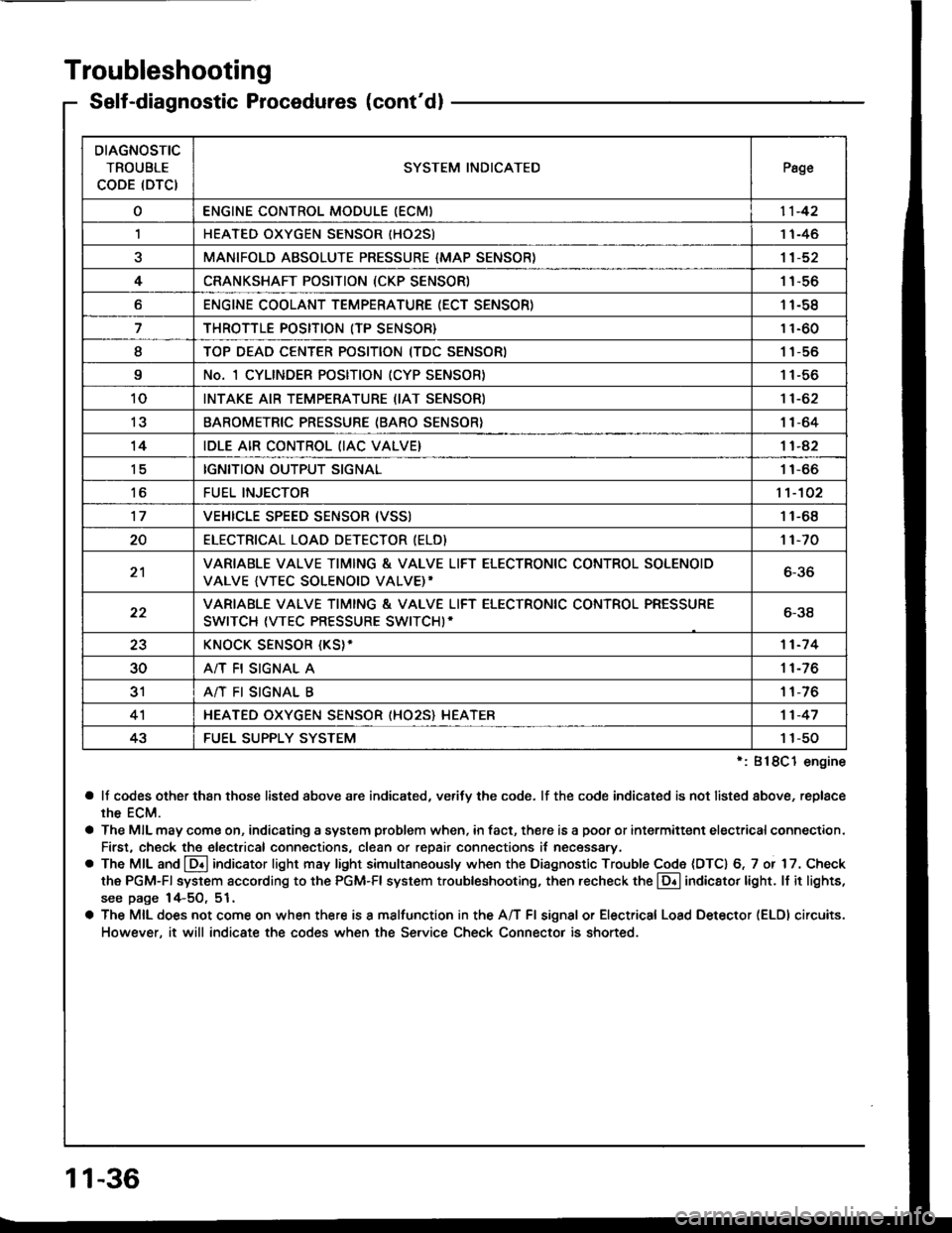
Troubleshooting
Self-diagnostic Procedures (cont'dl
':818C1 engine
a lf codes other than those listed above are indicated, verifv the code. lf the code indicated is not listed above, replace
rhe ECM.
a The MIL may come on, indicating a system problem when, in fact, there is a poor or intermittent electricalconnection.
First, check the electrical connections, clean or repair connections it necessary.
o The MIL and @ indicator light may light simultaneously when the Diagnostic Trouble Code (DTC) 6, 7 or 17. Check
the PGM-Fl system according to the PGM-Fl system troubleshooting, then recheck the l!! indicator light. ll it lights,
see page 14-5O, 51.
a The MIL does not come on when there is a malfunction in the A/T Fl signal or Electrical Load Detector (ELDI circuits.
However, it will indicate the codes when the Service Check Connector is shorted.
DIAGNOSTIC
TROUBLE
CODE (DTCISYSTEM INDICATEDPsge
oENGINE CONTROL MODULE IECM)11-42
,lHEATED OXYGEN SENSOR IHO25)1 1-46
aMANIFOLD ABSOLUTE PRESSURE {MAP SENSOR)11-52
4CRANKSHAFT POSITION (CKP SENSOR)1 1-56
oENGINE COOLANT TEMPERATURE (ECT SENSOR)11-58
THROTTLE POSITION (TP SENSOR}11-60
ITOP DEAD CENTER POSITION (TDC SENSORI1 1-56
9No. 1 CYLINDER POSITION (CYP SENSOR)1 1-56
10INTAKE AIR TEMPERATURE (IAT SENSOR)11-62
13BAROMETRIC PRESSURE (BARO SENSOR}1|-64
14IDLE AIR CONTROL (IAC VALVE}11-42
tcIGNITION OUTPUT SIGNAL11-66
toFUEL INJECTOR1't-102
17VEHICLE SPEED SENSOR {VSSI11-68
20ELECTRICAT LOAD DETECTOR (ELD)'t 1-70
21VARIABLE VALVE TIMING & VALVE LIFT ELECTRONIC CONTROL SOLENOID
VALVE {VTEC SOLENOID VALVE)'6-36
22VARIABLE VALVE TIMING & VALVE LIFT ELECTRONIC CONTROL PRESSURE
SWITCH (VTEC PRESSURE SWITCHI-6-38
23KNOCK SENSOR {KS}-11-7 4
30A/T FI SIGNAL A11-76
3'rA/T FI SIGNAL B1 1-76
4'lHEATED OXYGEN SENSOR (HO25} HEATER11-47
43FUEL SUPPLY SYSTEM1 1-50
11-36
Page 260 of 1413
![HONDA INTEGRA 1994 4.G Workshop Manual PGM-FI System
Electrical Load Detector (ELDI
tft;-]/ The Maltunction Indicaror Lamp (MlL) indicatss Diagnostic Trouble Code IDTC) 20: A probtem in-Li!- tne Electrical Load Detecror {ELD} circuit.
With HONDA INTEGRA 1994 4.G Workshop Manual PGM-FI System
Electrical Load Detector (ELDI
tft;-]/ The Maltunction Indicaror Lamp (MlL) indicatss Diagnostic Trouble Code IDTC) 20: A probtem in-Li!- tne Electrical Load Detecror {ELD} circuit.
With](/img/13/6067/w960_6067-259.png)
PGM-FI System
Electrical Load Detector (ELDI
tft;-]/ The Maltunction Indicaror Lamp (MlL) indicatss Diagnostic Trouble Code IDTC) 20: A probtem in-Li!- tne Electrical Load Detecror {ELD} circuit.
With lho SCS lhon connectolconnoctod {ree pago 11-34}, cod.20 is indicatod.
Do the ECM B6set Procedurs {seepage 1 'l-35).
Start engine and keep engin€speed at idle.Turn on headlights.
lntennlna tlllure, lyrtom lt Ol(!t irl. dm. (lgtt driv. mly [email protected] for Door connactlona oaloota wiro. rt C218 IELD, lndEctrt.
Ooes the MIL indicato code 20?
Romove the undgr-hood fusg/relay box and remove the tus6/relav box lowet cover.
Turn lhe ignition switch ON.
Measure voltage betw€on BLK/YEL (+l terminal and BLK (-)terminal.
Msasuro voltag€ b€tweon BLK/Y€L {+) terminal snd bodvground.ls there bartory voltagel
Rcpir oo.n in BLK wir.batwaan lha 3P connrc-tor lnd G2Ol {loc.t.dtroit ot angh|. comprn-m.r dghl .ld.l,
B.p.lr op.n in BLKrYEL wlrr b.-tw..n o.24ACG (ALn flcl115A: Bl88l .ngln!, 20 A:818C1cnginol fu!. In thr und.r{..htu.o/r.lly bor lnd tho 3P con-rcclo?.
View tromwire side
BLK (-)
(To page 11-7'l)
GRn/iED I - |
BLK/YEL I + I
11-70
Page 262 of 1413
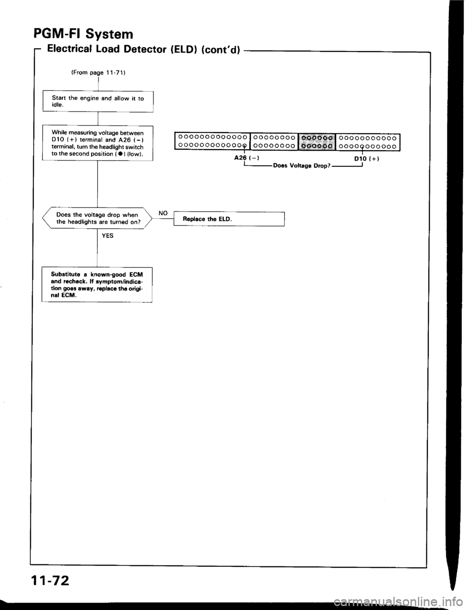
PGM-FI System
11-72
While measuring voltage betweenDlO 1+) terminal and 426 l-)terminal, turn the headlighr switchto the second position (a) {low).
Does the voltage drop whenthe headlights are turned on?
Subrtitute . known-good ECMand rochock. lt 3ymptom/indic€-tion goos away, ioplaco th6 origi-nal ECM.
Electrical Load Detector (ELD) (cont'd)
425 t-t D10 l+), Doos Volrago Orop? ----------------J
Page 1113 of 1413
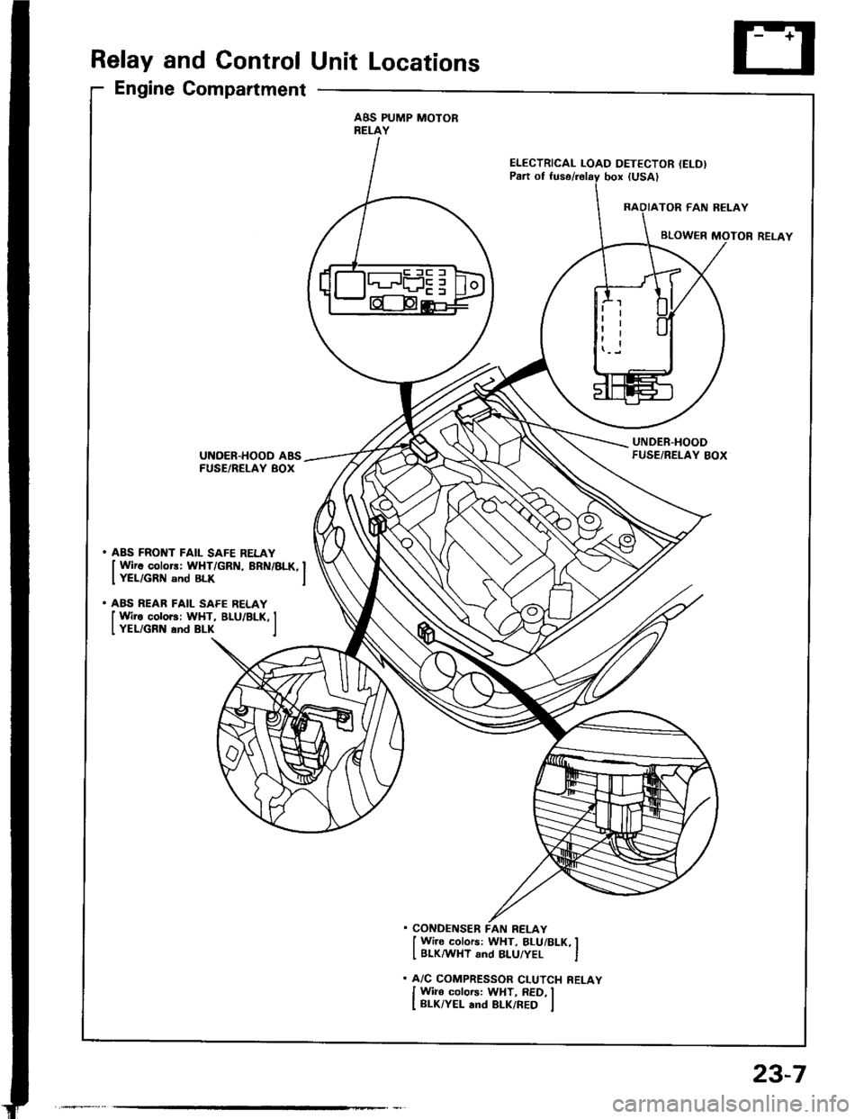
Relay and Control Unit Locations
Engine Compartment
ABS PUMP MOTORRELAY
ELECTRICAL LOAD DETECTOR (ELD)
UNDER.HOODFUSE/RELAY BOXUNOER-HOOD ABSFUSE/BELAY BOX
. ABS FRONT FAIL SAFE RELAY
I Wirc colors: WHT/GRN, BRN/BLK, IIYEL/GRN snd BLK I
. ABS REAR FAIL SAFE RELAY
I Wire colors: WHT, BLU/BLK, II YEL/GRN and BLK I
. CONDENSER FAN RELAY
I Wi]o colors: WHT, BLUi BLK, II BLKMHT and 8LU/YEL I
. A/C COMPRESSOR CLUTCH RELAY
I Wiro colors: WHT, RED, II BLK/YEL and BLK/RED I
23-7
Page 1204 of 1413
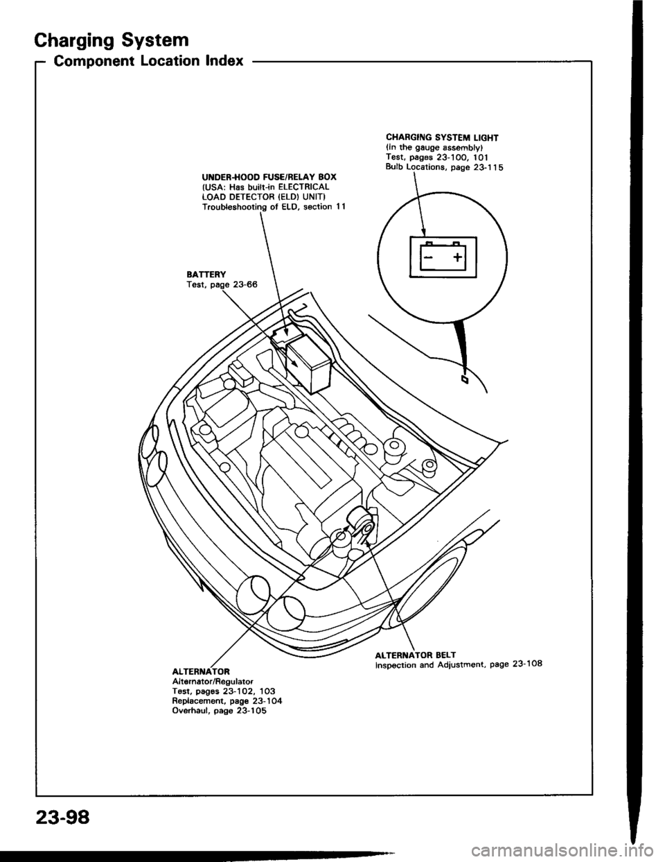
Charging System
Component Location lndex
UI{DER.HOOD FUSE/BELAY BOX(USA: Has builr-in ELECTRICALLOAD DETECTOR {ELD) UNIT)Troubleshooting ot ELD, s€ction 11
BATTERYTost,
CHARGING SYSTEM LIGHTlln the gauge sssemblylT€st. pages 23-1OO. 101Bulb Locations, page 23-1 1 5
ALTERNATOR BELTInspoction and Adiustment, page 23-108
Alt6rnator/RegulatorTosl, pag€s 23-102, 1O3Replacament. page 23-'l 04Ovsrhaul, pago 23-105
23-98