radiator HONDA INTEGRA 1998 4.G Service Manual
[x] Cancel search | Manufacturer: HONDA, Model Year: 1998, Model line: INTEGRA, Model: HONDA INTEGRA 1998 4.GPages: 1681, PDF Size: 54.22 MB
Page 1010 of 1681
.J
5.
6.
7.
8.
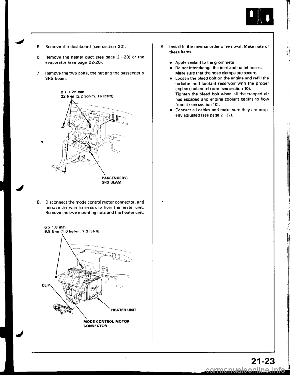
Remove the dashboard (see section 2O).
Remove the heater duct (see page 21 20) or the
evaporator lsee page 22-261.
Remove the two bolts, the nut and the passenger's
SRS beam.
PASSENGER'SSRS BEAM
Disconnect the mode control motor connector. and
remove the wire harness clip from the heater unit.
Remove the two mounting nuts and the heater unit.
6 x 1.0 mm9.8 N.m (1.0 kgf.m, 7.2 lbf.ftl
I r 1.25 mm22 N.m 12.2 kgf.m, 16 lbf'ft)
Il
I
I
lnstall in the reverse order of removal. Make note of
these items:
. Apply sealant to the grommets
. Do not interchange the inlet and outlet hoses.
Make sure that the hose clamps are secure.
. Loosen the bleed bolt on the engine and refill the
radiator and coolant reservoir with the proper
engine coolant minure (see section 10).
Tighten the bleed bolt when all the trapped air
has escaped and engine coolant begins to flow
from it (see section 10).
. Connect all cables and make sure they are prop-
erly adjusted (see page 2'l-271.
;!
i
21-23
Page 1022 of 1681
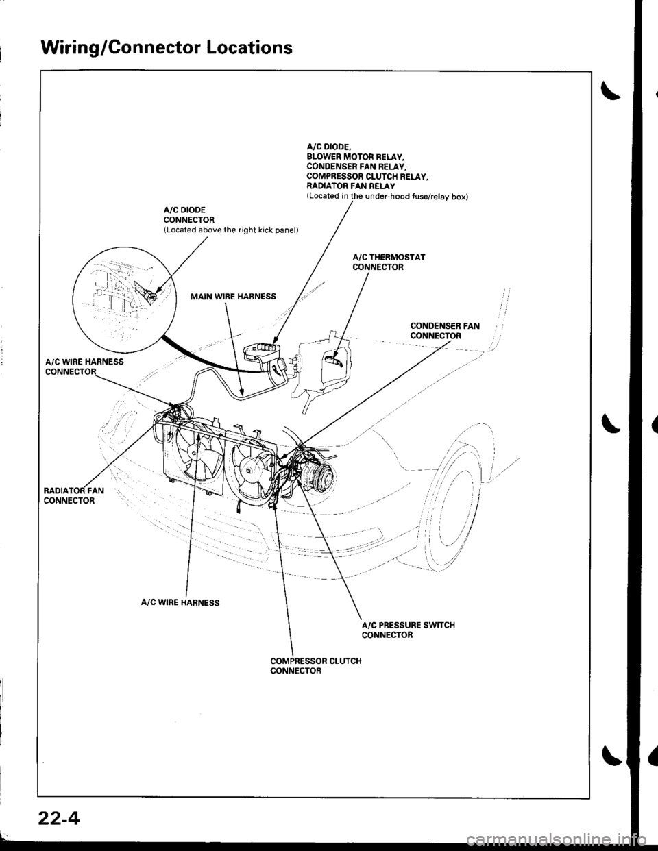
Wiring/Connector Locations
A/C DIODE.BLOWER MOTOR BELAY,CONOENSER FAN RELAY.COMPRESSOR CLUTCH RELAY,RADIATOR FAN REI-AY(Located in the under-hood tuse/relay box)
A/C DIODECONNECTORlLocated above the right kick panel)
MAIN WIBE HARNESS
A/C WINE HARNESS
A/C WIRE HARNESS
A/C PRESSURE SWITCHCONNECTOR
CLUTCHCONNECTOR
22-4
Page 1025 of 1681
J
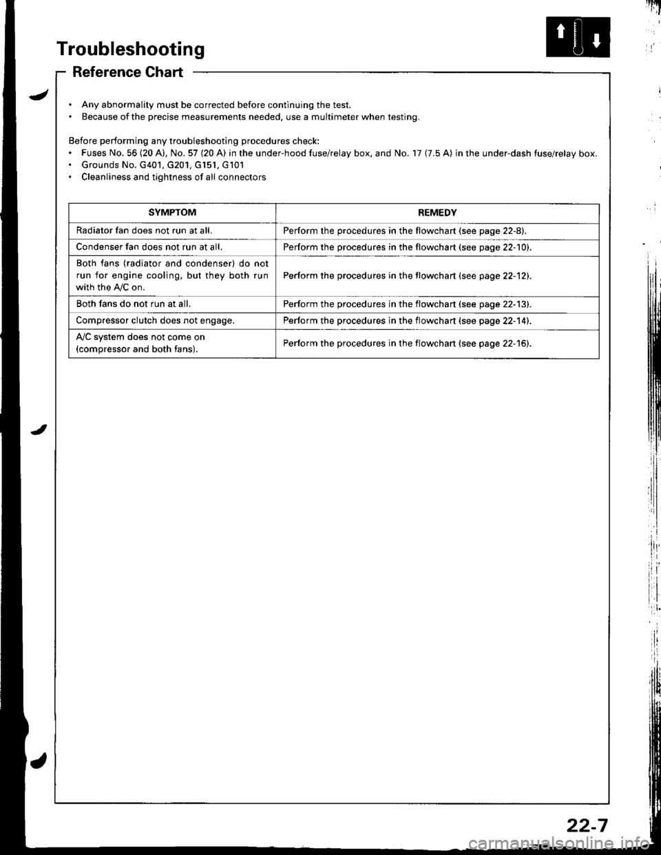
Troubleshooting
Reference Chart
. Any abnormality must be corrected before continuing the test.. Because of the precise measurements needed, use a multimeter when testing.
Before performing any troubleshooting procedures check:. Fuses No, 56 (20 A), No. 57 (20 A) in the under-hood fuse/relay box, and No. 17 {7.5 A) in rhe under-dash fuse/relay box.. Grounds No. G401, G201, G151, G101. Cleanliness and tightness of all connectors
I'IT
I
I
SYMPTOMREMEDY
Radiator fan does not run at all.Perform the procedures in the flowchart {see page 22-8).
Condenser fan does not run at all,Perform the procedures in the flowchart (see page 22-1O1.
Both fans {radiator and condenser) do not
run for engine cooling, but they both run
with the IVC on.
Perform the procedures in the tlowchart (see page 22-12).
Both fans do not run at all.Perform the procedures in the flowchart (see page 22-13).
Compressor clutch does not engage.Perform the procedures in the flowchart (see page 22-14).
l'lc system does not come on
{compressor and both fans).Perform the procedures in the flowchart (see page 22-15).
22-7
Page 1026 of 1681
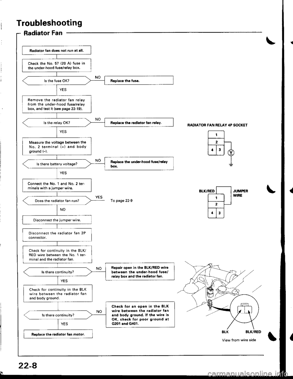
Troubleshooting
Radiator Fan
RADIATOR FAN RELAY 4P SOCKET
El2F-lt--T-- |
ujj I
I
",-*rrro [--l .u^rrrr
E lw'RE
l2-
trI
\
\
8LK BLK/RED
View from wire side\
Radiator lan does not run at all.
Chock the No. 57 (20 A) fuse in
the undeFhood fuse/relay box.
Remove the radiator tan relayfrom the under-hood fuse/rolaybox, and test it (see page 22-19).
Measuro the voltag€ betwogn theNo.2 terminal (+) and bodyground (-).
ls there battery voltage?
Connect the No. 1 and No. 2 ter-minals with a jumper wire.
Does the radiator fan run?
Check for continuity in the BLK/RED wire between the No. 1 ter-minal and the radiator fan.
Repair open in tho BLK/RED wir6b6twaon the undor-hood fuso/r6l6v box and the radirtorf6n.ls there continuity?
Check Ior continuity in the BLKwire between the radiator lanand body ground.
Chock for.n opon in tho BLKwiro botween tho .adiator fanand body ground, It tho wire i3OK, check for poor ground rtG201 and G401.
ls there continuity?
Roolace the radiator tan motor.
10 page 22-9
22-8
Page 1027 of 1681
![HONDA INTEGRA 1998 4.G Service Manual From page 22 8
RADIATORFAN RELAY
l---l
| 2 |
[T;]
I BrK/YEt
o)
I
RELAY 4P SOCKET
Disconnect the,umper wire andturn the ignition switch ON (II).
Measure the voltage between theNo. 4 terminal (+i and b HONDA INTEGRA 1998 4.G Service Manual From page 22 8
RADIATORFAN RELAY
l---l
| 2 |
[T;]
I BrK/YEt
o)
I
RELAY 4P SOCKET
Disconnect the,umper wire andturn the ignition switch ON (II).
Measure the voltage between theNo. 4 terminal (+i and b](/img/13/6069/w960_6069-1026.png)
From page 22 8
RADIATORFAN RELAY
l-'--l
| 2 |
[T;]
I BrK/YEt
o)
I
RELAY 4P SOCKET
Disconnect the,umper wire andturn the ignition switch ON (II).
Measure the voltage between theNo. 4 terminal (+i and bodyground ( ).
Ropair op€n in the GRN wire be-tween the undor-hood Iuse/.elay box and the A/C diode.
ls there battery voltage?
Repair open in the BLK/YEL wirebotwean the under-hood tuse/relay box snd the under-daahfuso/relay box,
22-9
Page 1030 of 1681
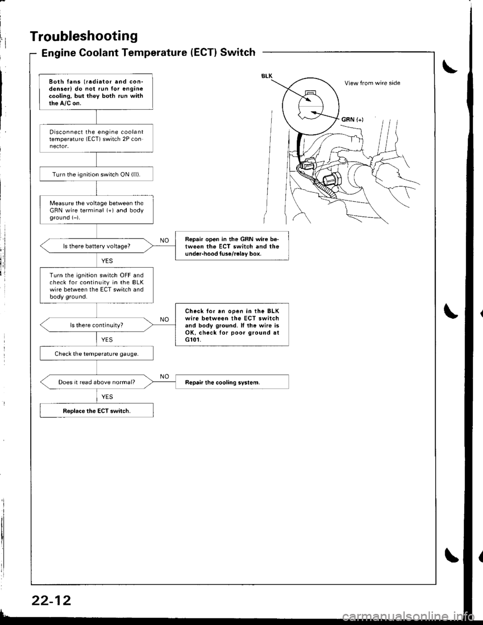
Troubleshooting
Engine Coolant Temperature(ECT}Switch
Both fans (radiator and con-denserl do not run for enginecooling, but they both run withthe A,/c on.
Disconnect the engine coolanttemperature lECT) switch 2P con
Turn the ignirion switch ON ( ll).
Measure the voltage between theGRN wire terminal (+) and bodyground (-)-
Repair open in the GRN wire b€-tween the ECT switch and theunder-hood luse/rel6v box,ls there battery voltageT
Turn the ignition switch OFF andcheck for continuity in the BLKwire between the ECT switch andbody ground.
Check for en ooen in the BLKwire between the ECT switchand body ground. ll th. wire isOK, check lor poor ground atG101.
ls there continuity?
Check the temperature gauge.
Does it read above normal?
View from wire side
GRN (+)
Page 1035 of 1681
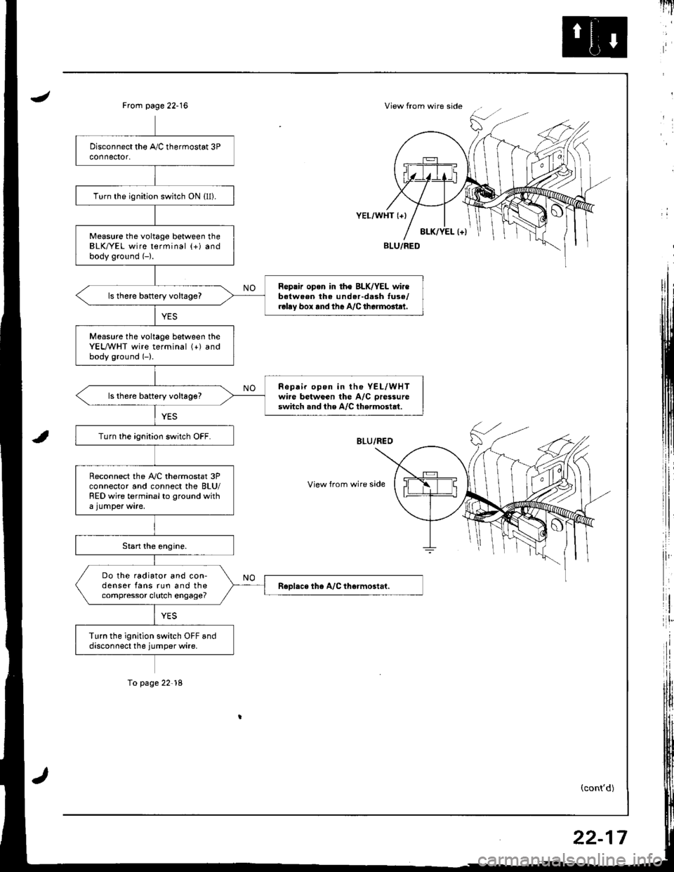
JView from wire sideFrom page 22-16
i,:,
il
rlt'
8LK/YEL l+)
YEL/WHT {+}
View from wire side
BLU/FED
(cont'd)
Turn the ignition switch ON {ll).
Measure the voltago between theBLK/YEL wire terminal (+) andbody ground (-).
Reprir opon in th€ BLK/YEL wir€batween the under-d.sh tuse/relay box rnd the A/C therm6tlt.
ls there battery vohageT
Moasure tho voltage between theYEL,A/VHT wire terminal (+) andbody ground (-).
Repair op6n in the YEL/WHTwire betwGen the A/C pressure
switch snd the A/C thermostat.ls th6re battery voltage?
Turn the ignition switch OFF.
Reconnect the A,/C thermostat 3Pconnector and connect the BLU/RED wire terminal to ground with
Do the radiator and con-denser fans run and thecompressor clutch engage?
Turn the ignition switch OFF anddisconnect the jumper wire.
To page 22'18
22-17
Page 1037 of 1681
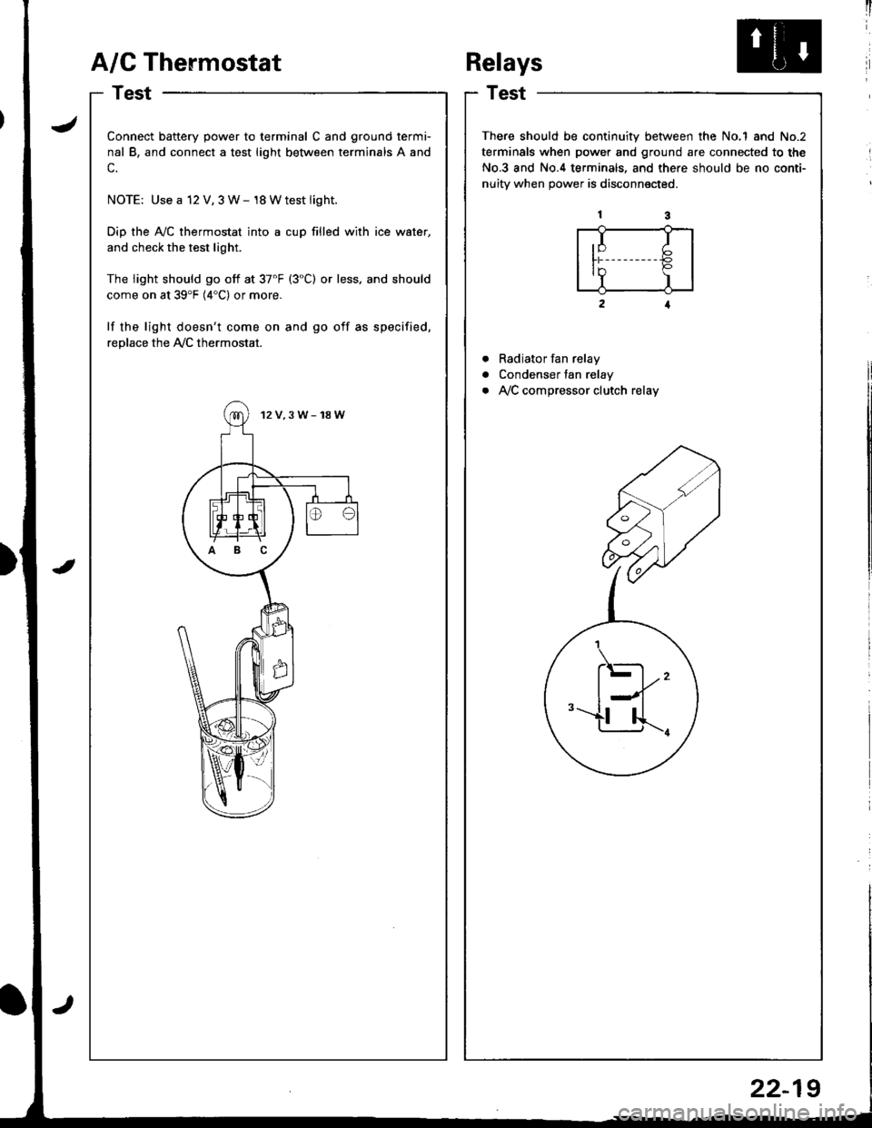
A/G Thermostat
I
I
a
a
a
t)
Connect battery power to terminal C and ground termi-
nal B, and connect a test light between terminals A and
c.
NOTE: Use a 12 V, 3 W- 18 Wtest light.
Dip the Ay'C thermostat into a cup filled with ice water,
and check the test light.
The light should go off at 37'F (3"C) or less. and should
come on at 39'F (4"C) or more.
lf the light doesn't come on and go off as specified,
replace the Ay'C thermostat.
12V,3W-18W
ABC
Relays
Test
There should be continuity between the No.1 and No.2
terminals when power and ground are connected to the
No.3 and No.4 terminals, and there should be no conti-
nuitv when Dower is disconnected.
Radiator fan relay
Condenser fan relay
Ay'C compressor clutch relay
,I I
ln P'Y )
.\-
l--l''-u...r.
22-19
Page 1041 of 1681
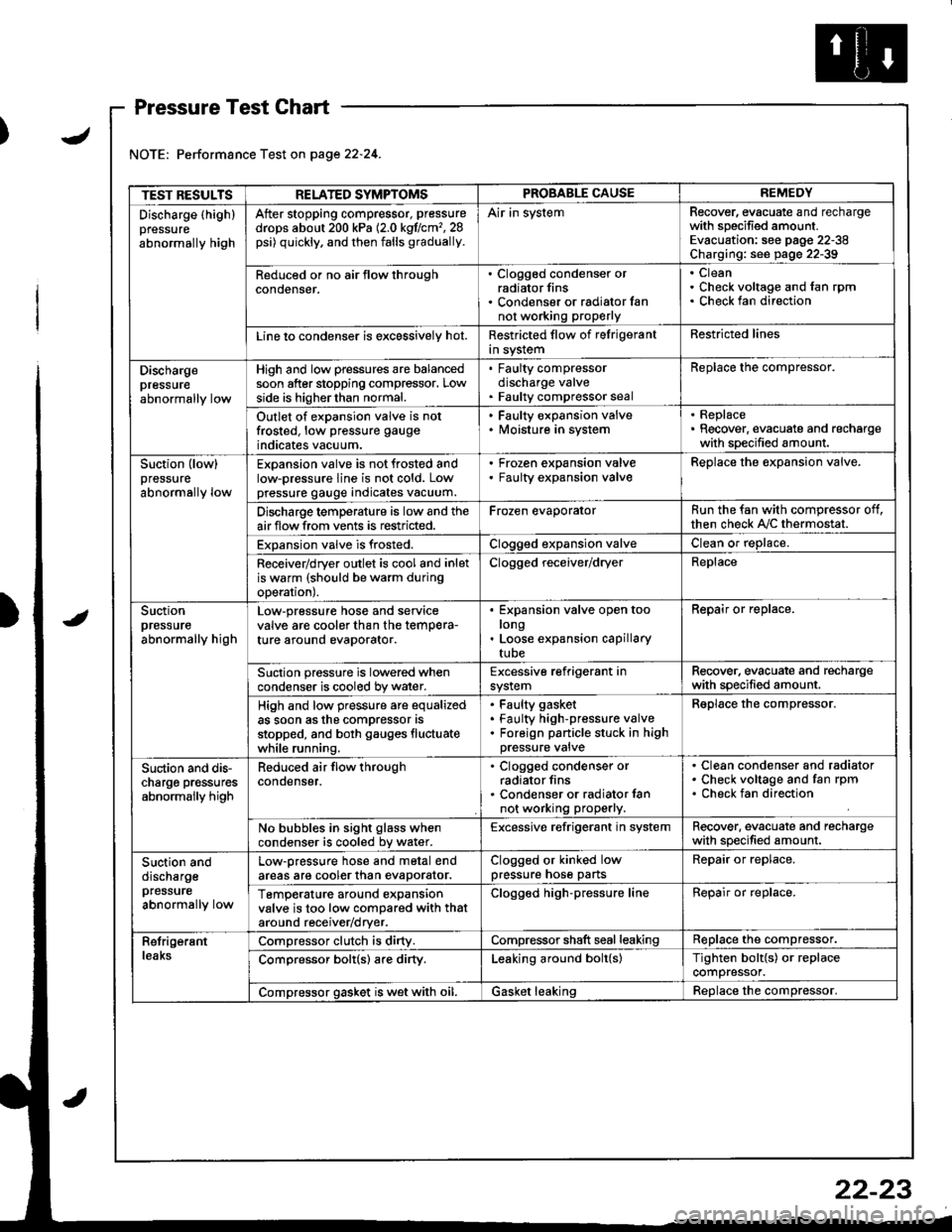
J
Pressure Test Chart
Performance Test on page 22.24.
TEST RESULTSRELATED SYMPTOMSPROBABLE CAUSEREMEDY
Discharge (highlpressure
abnormally high
After stopping compressor, pressure
drops about 200 kPa (2.0 kgflcm'�,28psi) quickly, and then falls gradually.
Air in systemRecover, evacuate and rechargewith specified amount.Evacuation: see pag€ 22-38Charging: see page 22-39
Reduced or no air tlow throughconoenser.
. Clogged condenser orradiator fins. Condenser or radialor fannot working proPerly
CleanCheck voltage and fan rpmCheck fan direction
Line lo condenser is excessively hot.Restricted flow of felrigerantin systemRestricted lines
Dischargepressureabnormally low
High and low pressures are balancedsoon after stopping compressor. Lowside is higherthan normal.
. Faulty compressordischarge valve. Faulty compressor seal
Replace the compressor.
Outlet of expansion valve is notfrosted, low pressure gauge
indicates vacuum.
. Faulty expansion valve. lvloisture in system
. Replace. Recover, evacuate and rechargewith specified amount.
Suction (low)pressure
abnormally low
Expansion valve is not frosted andlow-pressure line is not cold. Lowpressure gauge indicates vacuum.
Frozen expansion valveFaulty expansion valveReplace the expansion valve.
Discharge temperature is low and theairflow from vents is restricted.Frozen evaporatorRun the fan with compressor off,then check A,/C thermostat.
Expansion valve is frosted.Clogged expansion valveClean or replace.
Receiver/dryer outlet is cool and inletis warm (should be warm duringoperal|onJ.
Clogged receiver/dryerReplace
Suctionpressureabnormally high
Low-pressure hose and seryicevalve are cooler than the temPera-ture around evaporator.
Expansion valve open toolongLoose expansion capillarytube
Repair or replace.
Suction pressure is lowered whencondenser is cooled by water.Excessive refrigerant insystemRecover. evacuate and rechargewith specified amount.
High and low pressure are equalizedas soon asthe compressor asstopped, and both gauges fluctuatewhile running.
Faulty gasket
Faulty high-pressure valveForeign panicle stuck in highpressure valve
Reolace the comDressor.
Suction and dis-charge pr€ssuresabnormally high
Reduced air flow throughcondenser.
. Clogged condenser orradiator fins. Condenser or radiator lannot working properly.
Clean condenser and radiatorCheck voltage and fan rpmCheck fan direction
No bubbles in sight glass whencondenser is cooled bv water.Excessive refrigerant in systemRecover. evacuate and rechargewith specified amount.
Suction anddischargepfessure
abnormally low
Low-pressure hose and metal endareas are cooler than evaDorator.Clogged or kinked lowpressure hose partsRepair or replace.
TemP€rature around expansionvalve is too low compared with thataround receiv€r/dryer.
Clogged high-pressure lineRepair or replace.
RetrigerantleaksCompressor clutch is dirty.Compressor shaft seal leakingReplace the compressor.
Comoressor bolt(s) are dirty.Leaking around bolt(s)Tighten bolt{s) or replacecompressor.
Compressor gasket is wet with oil.Gasket leakingReolace the comoressor.
22-23
Page 1048 of 1681
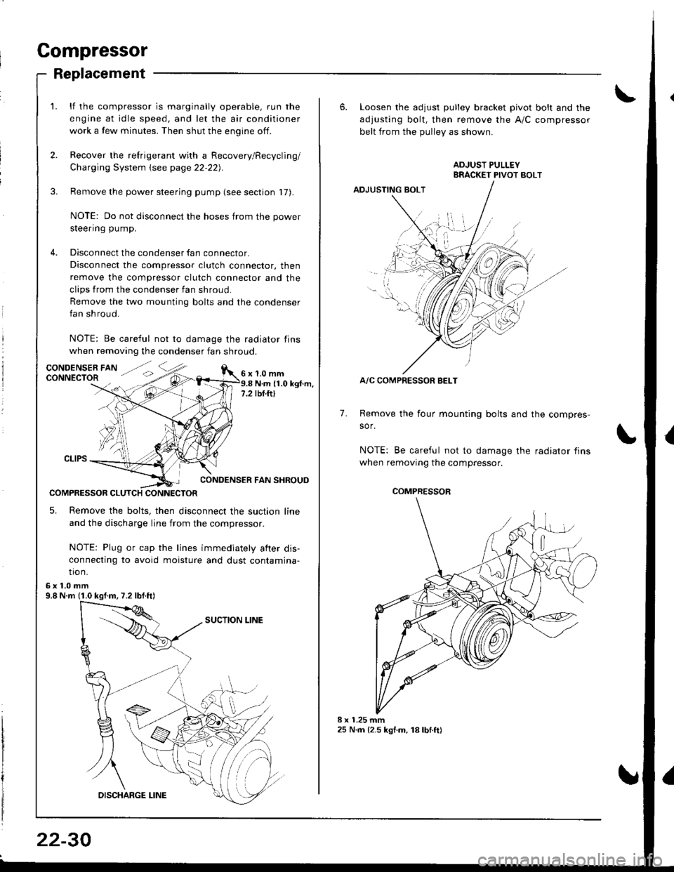
Compressor
Replacement
lf the compressor is marginally operable, run the
engine at idle speed, and let the air conditioner
work a few minutes. Then shut the engine off.
Recover the refrigerant with a Recovery/Recycling/
Charging System \see page 22-22).
Remove the power steering pump (see section 17).
NOTE: Do not disconnect the hoses from the power
steering pump.
Disconnect the condenser fan connector.
Disconnect the compressor clutch connector, then
remove the compressor clutch connector and the
clips from the condenser fan shroud
Remove the two mounting bolts and the condenser
fan shroud.
NOTE: Be careful not to damage the radiator fins
when removing the condenser fan shroud.
1.0 mmN.m (1.0 kgt.m,rbf.ftt
CONDENSER FAN SHROUD
COMPRESSOR CLUTCH CONNECTOR
5. Remove the bolts, then disconnect the suction line
and the discharge line from the compressor.
NOTE: Plug or cap the lines immediately aiter dis-
connecting to avoid moisture and dust contamina-
tio n.
6x1.0mm9.8 N.m (1.0 kgf.m, 7.2 lbf.ft)
22-30
6. Loosen the adjusl pulley bracket pivot bolt and the
adjusting bolt, then remove the A/C compressor
belt from the Dullev as shown.
ADJUSTING BOLT
A/C COMPRESSOR BELT
Remove the four mounting bolts and the compres-
sor.
NOTE: Be careful not to damage the radiator fins
when removing the compressor.
7.
./.,
COMPRESSOR