bolt pattern HONDA INTEGRA 1998 4.G Workshop Manual
[x] Cancel search | Manufacturer: HONDA, Model Year: 1998, Model line: INTEGRA, Model: HONDA INTEGRA 1998 4.GPages: 1681, PDF Size: 54.22 MB
Page 93 of 1681
\-
L
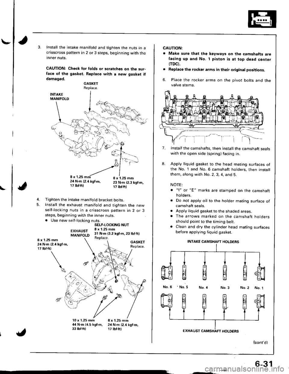
Install the intake manifold and tighten the nuts in acflsscross pattern in 2 or 3 steps. beginning with theinner nuts.
CAUTION: Check lor folds or scratches on the sur-face ol the gasket. Replace with a new gasket ildamaged.GASKETReplace.
INTAKEMANIFOLD
4. Tighten the intake manifold bracket bolts.5. Install the exhaust maniiold and tighten the newself-locking nuts in a crisscross pattern in 2 or 3steps, beginning with the inner nuts.. Use new self-locking nuts.
EXHAUSTMANIFOLD
GASKETReplace.
4
10 x 1.25 mm 8 x 1.25 mm4,{ N.rn 14.5 kgf.m, 24 N.m {2.4 kgtm,33 tbf.ftl '17 tbf.ft)
SELF.LOCKING NUT8 x 1.25 mm31 N.m (3.2 kgt m,23 lbf.ft)Replace.1 .25 mmN.m {2.4 kg{.m,rbrftt
\q
8x2417
",', r, ^-'-"-!,1,,,';-21N.m l2.1kglm, 23 N.m (2.3 ksf.m,17lbf.ftl 17 tbf.ftr
6-31
CAUTION:
. Make sure that the keyways on the camshafts aretacing up and No. 1 piston is at top dead cenier
tTDCt.. Replacethe rocker arms in their original positions.
6. Place the rocker arms on the pivot bolts and thevalve stems.
7.
8.
Install the camshafts, then install the camshaft sealswith the open side (spring) facing in.
Apply liquid gasket to the head mating surfaces otthe No. 1 and No. 6 camshaft holders, then installthem, along with No.2,3, 4, and 5.
NOTE:
. "l" or "E' marks are stamped on the camshaftholders.
. Do not apply oil to the holder mating surface ofcamshaft seals.. Apply liquid gasket to the shaded areas.. The arrows marked on the camshaft holdersshould point to the timing belt.. Clean and dry the cylinder head mating surfacesbefore applying liquid gasket.
INTAKE CAMSHAFT HOLDERS
No.6 No.5No.4No.3 No.2 No. 1
{cont'd)
Page 364 of 1681
Pressure Plate
Removal/lnspectaon
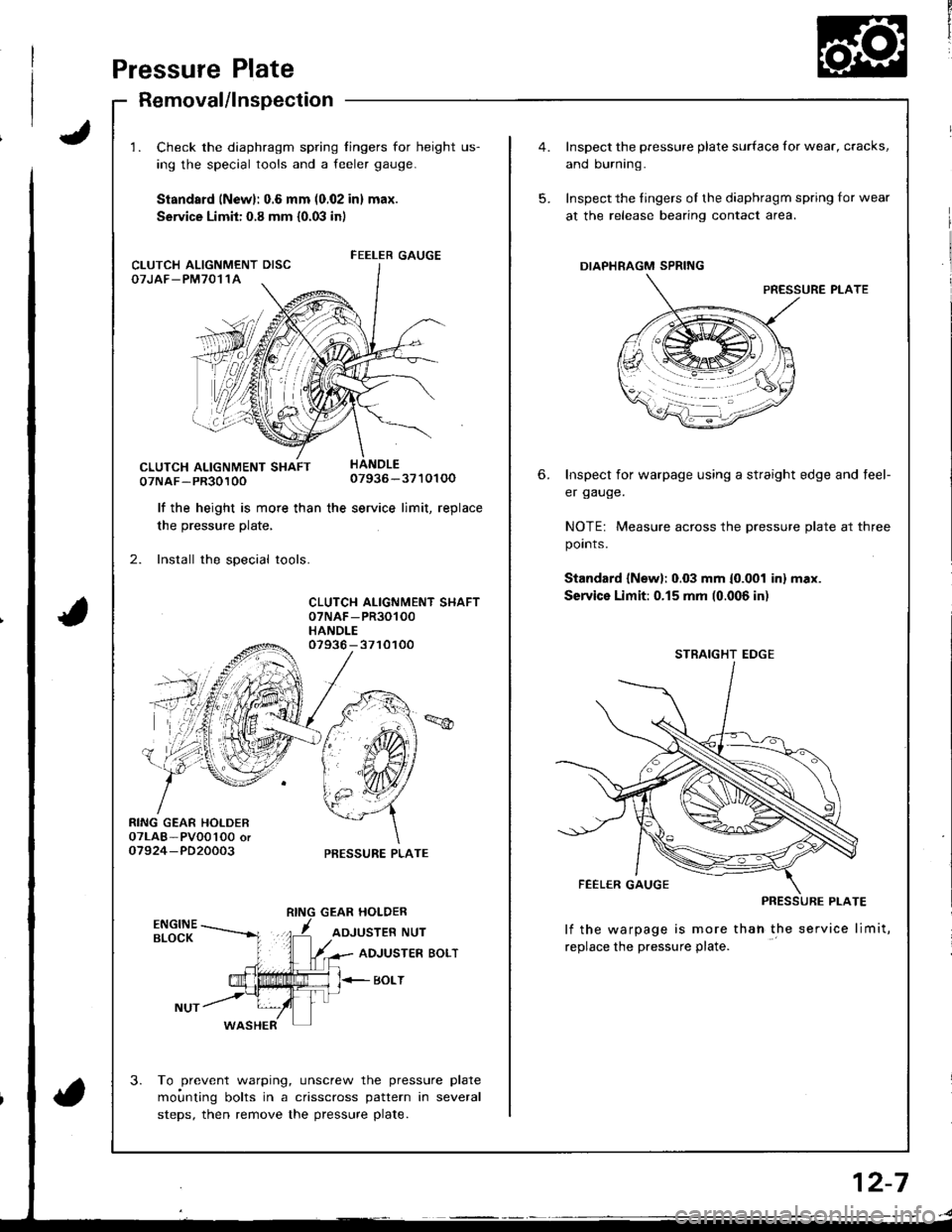
1. Check the diaphragm spring fingers for height us-
ing the special tools and a feeler gauge.
Standsrd (New): 0.6 mm (0.02 in) max.
Service Limit: 0.8 mm {0.03 in)
07NAF-PR3010007936-3710100
lf the height is more than the service limit, replacethe hro..rr.a nlefe
2. Install the special tools.
CLUTCH ALIGNMENT SHAFT07NAF -PR30100
HANDLE
RING GEAR HOLDER07LAB- PVOo'l0O oro7924-PD20003
07936 - 3710100
PRESSURE PLATE
GEAR HOLDER
ADJUSTER NUT
3.
ADJUSTER BOLT
BOLT
WASHER
To prevent warping, unscrew the pressure plate
moi.rnting bolts in a crisscross pattern in several
steps, then remove the pressure plate.
FEELER GAUGECLUTCH ALIGNMENT DISCOTJAF_PM7011A
5.
6.
Inspect the pressure plate surface for wear, cracks,
and burning.
Inspect the fingers of the diaphragm spring for wear
at the release bearing contact area.
DIAPHRAGM SPRING
PRESSURE PLATE
Inspect for warpage using a straight edge and teel-
er gauge.
NOTE: Measure across the pressure plate at three
points.
Standard {New}: 0.03 mm {0.001 inl max.
Service Limit:0.15 mm (0.006 in)
lf the warpage is more thah the service limit,
replace the pressure plate.
STRAIGHT EDGE
2-7
Page 366 of 1681
Flywheel, Flywheel Bearing
Inspection
t
',4
i
Replacement
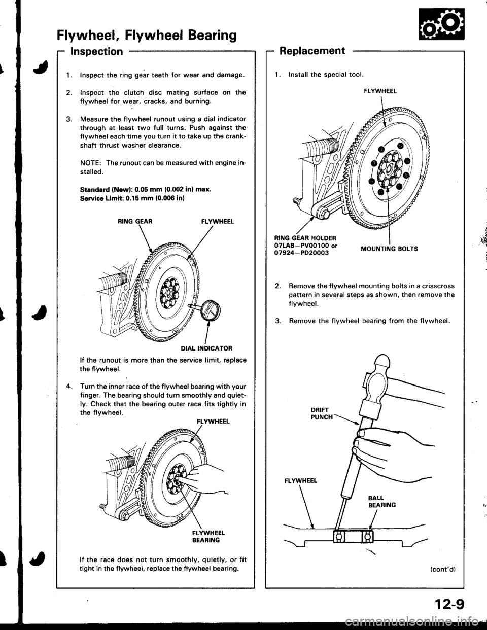
1. Install the special tool.
MOUNTING BOLTS
Remove the flywheel mounting bolts in a crisscrosspattern in several steps as shown, then.emove the
Jlvwheel.
Bemove the flywheel bearing from the flywheel.
(cont'd)
FLYWHEEL
I
1.Inspect the ring gear teeth tor wear and damage.
Inspect the clutch disc mating surtace on the
flywheel for wear, cracks, and burning.
l\,reasure the flywheel runout using a dial indicator
through at least two full turns. Push agsinst the
Jlywheel each time you turn it to take up the crank-
shatt thrust washer clearance.
NOTE: The runout can ba measured with engine in-
stalled.
SiEndrrd (Ncw): 0.05 mm (0.002 inl max.
SerYicc Llmh: 0.15 mm (0.006 inl
DIAL INOICATOR
lf the runout is more than the service limit, reolace
the flywheel.
Turn the inner race of the flywheel bearing with your
tinger. The bearing should turn smoothly and quiet-
ly. Check that the bearing outer race tits tightly in
the flvwheel.
FLYWHEELBEARING
lf the race does not turn smoothly, quietly, or tit
tight in the flywheel, replace the flywheel bearing.
4.
FLYWHEEL
12-9
Page 367 of 1681
Clutch Disc,
Flywheel, Flywheel BearingPressure Plate
Replacement (cont'd)Installation
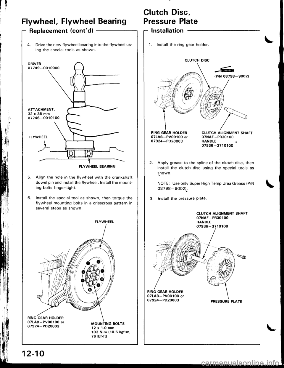
1. Install the ring gear holder.
CLUTCH DISC
1tti
CLUTCH ALIGNMENT SHAFT07NAF-PR30100HANDLE07936 -3710100
Apply grease to the spline ot the clutch disc, then
install the clutch disc using the special tools as
shown.
NOTE: Use only Super High Temp Urea Grease (P/N
o8798 9002).
3. Insrall the pressure Plate.
CLUTCH ALIGNMENT SHAFT07NAF-PR30100HANDLE07936-3710100
RING GEAR HOI-DER07LAB - PV001O0 or07924-PD20003
4. Drive the new flywheel bearing into the flywheel us-
ing the special tools as shown.
DRIVER07749 -0010000
FLYWHEEL
Align the hole in the llywheel with the crankshalt
dowel pin and installthe flywheel. Installthe mount-
ing bolts fingertight.
Install the special tool as shown, then torque the
flvwheel mounting bolts in a crisscross pattern in
several steps as shown-
6.
ATTACHMENT,32x35mm07746 0010100
5.
RING GEAE HOLDER07LAB-Pv00100 or07924-PD20003MOUNTING BOLTS12 x 1.0 mm103 N.m (10.5 kgf .m,
76 tbt.frl
FLYWHEEL BEARING
FLYWHEEL
6!-o
&#,oit
12-10
PRESSURE PLATE
Page 368 of 1681
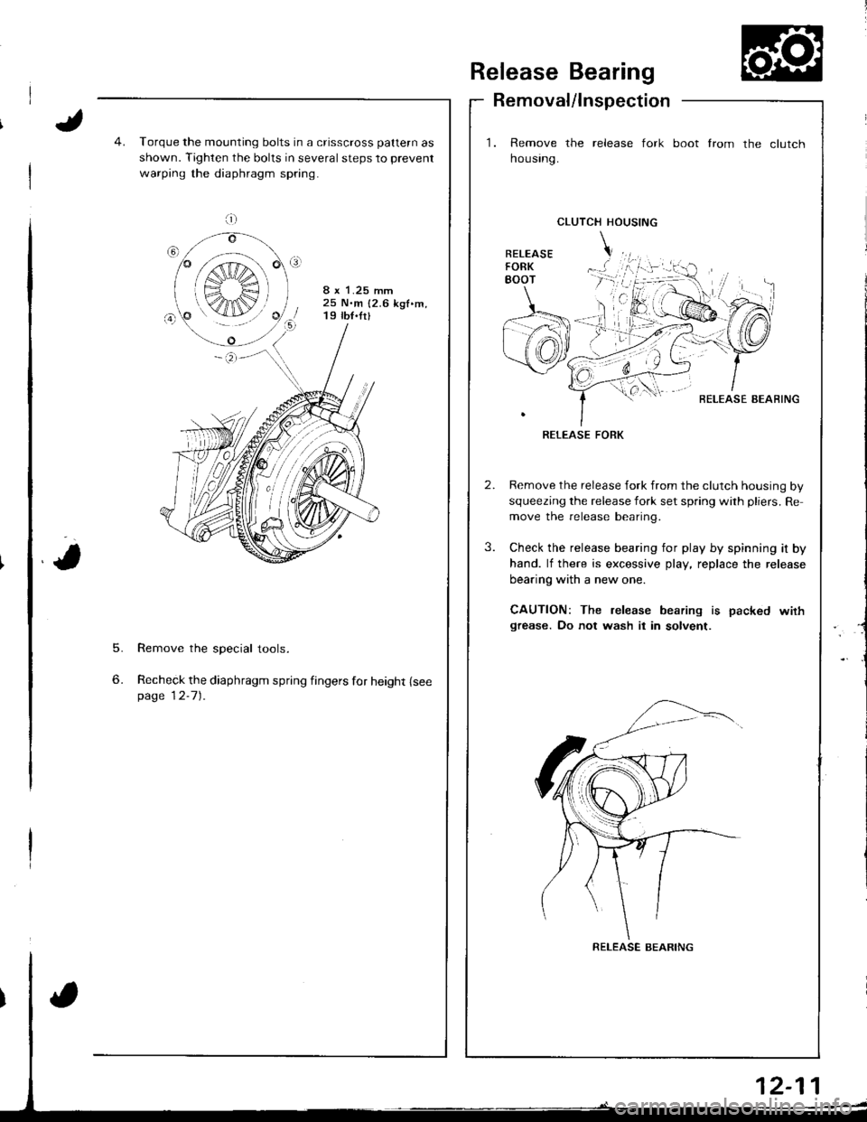
Release Bearing
Removal/lnspection
1. Remove the release fork
housrng.
boot from the clutch
5.
6.
Torque the mounting bolts in a crisscross pattern as
shown. Tighten the bolts in several steps to prevent
warping the diaphragm spring.
8 x 1.25 mm25 N.m {2.6 kgf.m,19 tb{.fr}
Remove the special tools.
Recheck the diaphragm spring fingers for height {seepage 12-7).
CLUTCH HOUSING
BELEASE AEAFING
RELEASE FORK
Remove the release fork from the clutch housing by
squeezing the release fork set spring with pliers. Re
move the release bearing.
Check the release bearing for play by spinning it by
hand. lf there is excessive play, replace the release
bearing with a new one.
CAUTION: The release bearing is packed wirhgrease. Do not wash it in solvent.
a;;;:
S",€ r
K4IN/
RELEASE BEARING
Page 376 of 1681
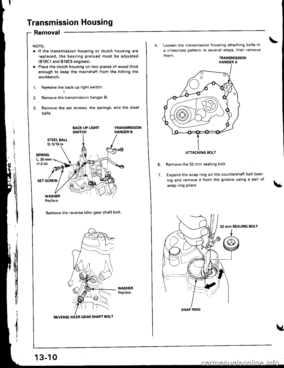
Transmission Housing
Removal
NOTE:
. lf tho transmission housing or clutch housing are
replaced, the bearing preload must be adjusted
(818C1 8nd 818C5 engines).
. Place the clutch housing on two pieces of wood thick
enough to keep the mainshaft from the hifting the
workbench.
1. Remove the back-up light switch.\
2. Remove the transmission hanger B.
3. Remove the set screws, the springs, and the steel
balls.
BACK-UP LIGHTswrTcHTRANSMISSIONHANGER B
STEEL BALLD. 5/16 in
SET SCREW
WASHERReplace.
Remove the reverse idler gear shaft bolt.
13-10
5. Loosen the transmission housing attaching bolts in
a crisscross pattern in several steps, then remove
them.TRANSMISSION
Remove the 32 mm sealing bolt.
Expand the snap ring on the countershaft ball bear-
ing and remove it from the groove using a pair of
snap ring pliers.
6.
7.
ATTACHING BOLT
SNAP RING
32 mm SEALING BoLT
Page 585 of 1681
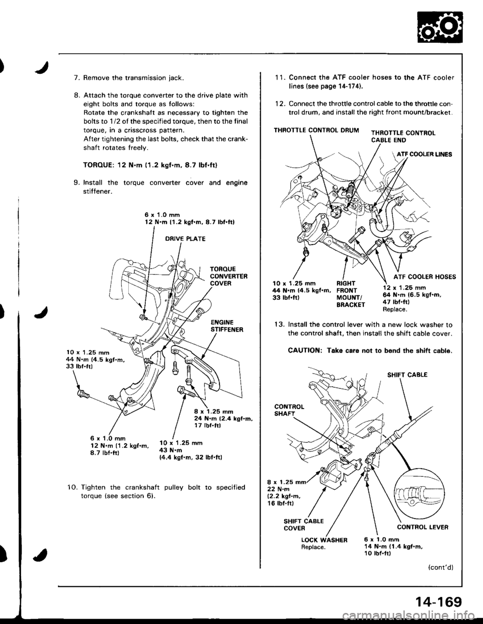
7.
10 x 1.25 mm1+4 N.m (4.5 kgt.m,33 tbf.ft)
TOROUECONVERTERCOVER
EI{GINESTIFFEI{ER
I x 1.25 mm24 N.m 12.4 kgf.m,17 rbf.ftl
8.
Remove the transmission jack.
Attach the torque converter to the drive plate with
eight bolts and torque as lollows:
Rotate the crankshatt as necessary to tighten the
bolts to 1/2 of the specified torque, then to the final
torque, in a crisscross pattern.
After tightening the last bolts, check that the crank-
shaft rotates freely.
TOROUE: 12 N.m (1.2 kgf.m. 8.7 lbf.ft)
Install the torque converter cover and engine
stitfener.
6 x 1.0 mm12 N'm l'1.2 kgl.m,8.7 lbl.ftl
ORIVE PLATE
9.
6 x '1.0 mm12 N'm ('1.2 kgf.m,8.7 tbt.fr)
l0 x 1.25 mm43 N.m{4.4 kgf.m, 32 lbl.ftl
10.Tighten the crankshaft
torque (see section 6).
pulley bolt to specified
)
1 1. Connect the ATF cooler hoses to the ATF cooler
lines (see page 14-174).
12. Connect the throttle control cable to the throtrle con,
trol drum, and installthe right front mount/brackel.
THROTTLE CONTROL DRUMTHROTTLE CONTROLCABLE END
ATF COOLER UNES
ATF COOLER HOSESlO x 1.25 mm RIGHT44 N.m 14.5 kgf.m, FRONT33 tbf.ft) MoUNT/BRACKET
13.
LOCK WASHERReplace.6 x 1.0 mft14 N.m (1.4 kgt.m,10 tbf.fr)
12 x 'l ,25 nn64 N.rh 16.5 kgf.m,47 tbt.ft)Replace.
SHIFT CABLE
CONTROL LEVER
(cont'dl
Install the control lever with a new lock washer to
the control shalt, then installthe shift cable cover.
CAUTION: Take care not to b6nd the shitt cable.
8 x 1.2522 N-m12.2 kgt.n.'t6 tbl.tr,
SHIFT CABLECOVER
14-169
Page 602 of 1681

Differential (81881 engine)
Backlash Inspection
Place differential assembly on V-blocks and install
both axles.
N4easure the backlash ot both pinion gears
Standa.d (Newl: O.O5-0.15 mm (O.OO2-0.006 in)
3. It the backlash is not within the standard, replace
the differential carrier.
Final Driven Gear RePlacement
1. Remove the bolts in a crisscross pattern ln several
steps, then remove the linal driven gear trom the
differential carrier.
NOTE: The final driven gear bolts have left-hand
tnreaos.
10 x 1.0 mm101 N'm 110.3 kgf'm, 74.5 lbf'fll
Left-hand threads
FINAL DRIVEN GEAR
OIFFERENTIALCARRIER
Install the final driven gear by tightening the bolts
in a crissc.oss pattern in several steps.
OIAL INDICATOR
Charnfer on inside diameter ottinal driven gear faces carrier.
\
15-4
Page 610 of 1681
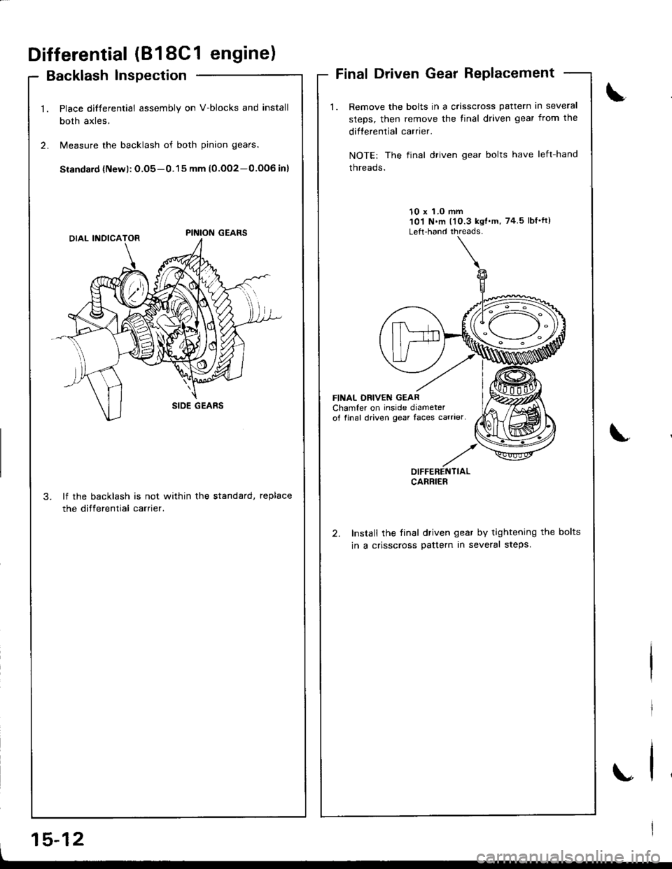
Differential (818C1 engine)
Backlash lnspection
Place differential assembly on V-blocks and install
both axles,
Measure the backlash of both pinion gears.
Siandard {Newl: O.O5-0.15 mm (0.OO2-0.OOG in}
lf the backlash is not within the standard, replace
the differential carrier.
Final Driven Gear Replacement
Remove the bolts in a crisscross pattern in several
steps, then remove the tinal driven gear from the
difterential carrier.
NOTE: The final driven gear bolts have left-hand
threads.
10 x 'l.O mm101 N.m l'10.3 kgt'm, 74 5lbf'ft)
Left-hand threads-
FINAL DBIVEN GEARChamfer on inside diameterof final driven gear Iaces carrier
Install the final driven gear by tightening the bolts
in a crisscross pattern in several steps.
\
.,
OIFFERENTIALCARRIER
I
15-12