Hyundai Accent 2006 Owner's Manual
Manufacturer: HYUNDAI, Model Year: 2006, Model line: Accent, Model: Hyundai Accent 2006Pages: 599, PDF Size: 17.59 MB
Page 451 of 599
1CONTROLS AND EQUIPMENT
44
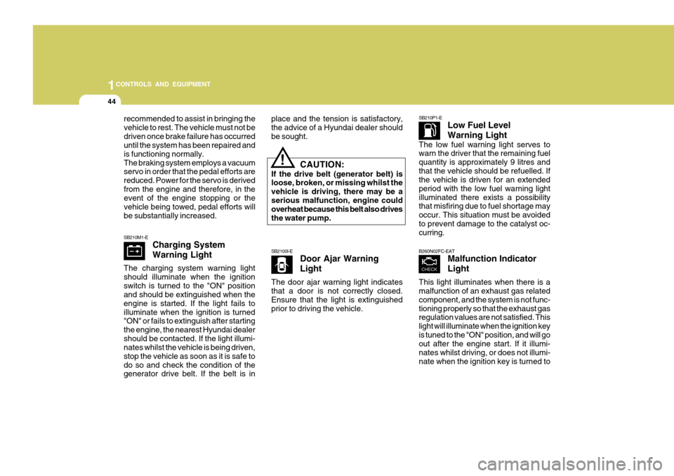
SB210M1-E Charging System Warning Light
The charging system warning light should illuminate when the ignitionswitch is turned to the "ON" position and should be extinguished when the engine is started. If the light fails toilluminate when the ignition is turned "ON" or fails to extinguish after starting the engine, the nearest Hyundai dealershould be contacted. If the light illumi- nates whilst the vehicle is being driven, stop the vehicle as soon as it is safe todo so and check the condition of the generator drive belt. If the belt is in SB2100I-E
Door Ajar Warning Light
The door ajar warning light indicates that a door is not correctly closed. Ensure that the light is extinguishedprior to driving the vehicle. SB210P1-E
Low Fuel Level Warning Light
The low fuel warning light serves to warn the driver that the remaining fuel quantity is approximately 9 litres andthat the vehicle should be refuelled. If the vehicle is driven for an extended period with the low fuel warning lightilluminated there exists a possibility that misfiring due to fuel shortage may occur. This situation must be avoidedto prevent damage to the catalyst oc- curring.
recommended to assist in bringing the vehicle to rest. The vehicle must not bedriven once brake failure has occurred until the system has been repaired and is functioning normally.The braking system employs a vacuum servo in order that the pedal efforts are reduced. Power for the servo is derivedfrom the engine and therefore, in the event of the engine stopping or the vehicle being towed, pedal efforts willbe substantially increased.
place and the tension is satisfactory, the advice of a Hyundai dealer shouldbe sought.
CAUTION:
If the drive belt (generator belt) is loose, broken, or missing whilst the vehicle is driving, there may be aserious malfunction, engine could overheat because this belt also drives the water pump.
!
B260N02FC-EAT Malfunction Indicator Light
This light illuminates when there is a malfunction of an exhaust gas related component, and the system is not func-tioning properly so that the exhaust gas regulation values are not satisfied. This light will illuminate when the ignition keyis tuned to the "ON" position, and will go out after the engine start. If it illumi- nates whilst driving, or does not illumi-nate when the ignition key is turned to
Page 452 of 599
45
1
CONTROLS AND EQUIPMENT
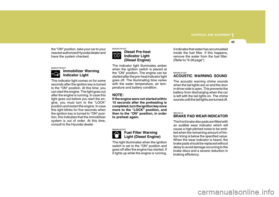
B260S01B-GAT
Diesel Pre-heat Indicator Light(Diesel Engine)
The indicator light illuminates amber when the ignition switch is placed at the "ON" position. The engine can bestarted after the pre-heat indicator light goes off. The illuminating time varies with the water temperature, air tem-perature and battery condition. NOTE: If the engine were not started within 10 seconds after the preheating is completed, turn the ignition key once more to the "LOCK" position, andthen to the "ON" position, in order to preheat again.
B260U01TB-EAT Immobilizer Warning Indicator Light
This indicator light comes on for some seconds after the ignition key is turned to the "ON" position. At this time, youcan start the engine. The light goes out after the engine is running. In case this light goes out before you start the en-gine, you must turn to the "LOCK" position and restart the engine. In case this light blinks for five seconds whenthe ignition key is turned to "ON" posi- tion, this indicates that the immobilizer system is out of order. At this time,consult to the Hyundai dealer.
B900A01A-GAT ACOUSTIC WARNING SOUND The acoustic warning chime sounds when the tail lights are on and the door in driver side is open. This prevents the battery from discharging when the caris left with the tail lights on. The chime sounds until the tail lights are turned off.
B265A01B-GAT Fuel Filter Warning Light (Diesel Engine)
This light illuminates when the ignition switch is set to the "ON" position and goes off after the engine has started. If it lights up while the engine is running,
the "ON" position, take your car to your nearest authorized Hyundai dealer andhave the system checked. it indicates that water has accumulatedinside the fuel filter. If this happens,remove the water from the fuel filter. (Refer to "6-26 page") SB210S1-E BRAKE PAD WEAR INDICATOR The front brake disc pads are fitted with an audible wear indicator which will cause a high pitched noise to be emit- ted when the remaining amount of fric-tion lining is below the specified value. When the wear indicator is heard, the brake pads should be replaced withoutdelay to avoid damage occurring to the brake discs and a severe reduction in braking efficiency.
Page 453 of 599
1CONTROLS AND EQUIPMENT
46
!
heating cannot be readily established, the assistance of a Hyundai dealershould be sought.
WARNING:
The engine cooling system is pres-surized and removal of the radiatorcap when the engine is hot may cause hot water and steam to be ejected from the radiator resulting inburns and scalding. The radiator cap must only be removed when the en- gine has cooled. Do not add coldwater to a hot engine to avoid the possibility of engine damage. The use of plain water in the coolingsystem is not recommended since the aluminium components of the cooling system require the use of acorrosion inhibitor found in the rec- ommended Ethylene Glycol type anti freeze solutions.
INSTRUMENT CLUSTER
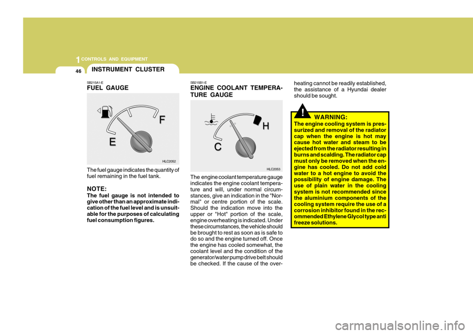
SB215B1-E ENGINE COOLANT TEMPERA- TURE GAUGE The engine coolant temperature gauge indicates the engine coolant tempera- ture and will, under normal circum-stances, give an indication in the "Nor- mal" or centre portion of the scale. Should the indication move into theupper or "Hot" portion of the scale, engine overheating is indicated. Under these circumstances, the vehicle shouldbe brought to rest as soon as is safe to do so and the engine turned off. Once the engine has cooled somewhat, thecoolant level and the condition of the generator/water pump drive belt should be checked. If the cause of the over-
The fuel gauge indicates the quantity offuel remaining in the fuel tank. NOTE: The fuel gauge is not intended to give other than an approximate indi- cation of the fuel level and is unsuit-able for the purposes of calculating fuel consumption figures.
SB215A1-E FUEL GAUGE
HLC2053
HLC2052
Page 454 of 599
47
1
CONTROLS AND EQUIPMENT
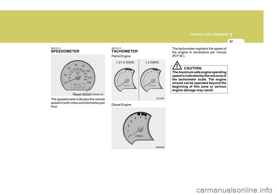
SB215C1-E SPEEDOMETER
The speedometer indicates the vehicle speed in both miles and kilometres perhour. B300A01A-E
HLC2050
1.3/1.5 SOHC
B330A03A
1.6 DOHC
Diesel Engine
Petrol Engine
SB215F1-E TACHOMETER
Reset Switch The tachometer registers the speed of the engine in revolutions per minute(R.P.M.).
!
CAUTION:
The maximum safe engine operating speed is indicated by the red zone of the tachometer scale. The engineshould not be operated beyond the beginning of this zone or serious engine damage may result.
Page 455 of 599
1CONTROLS AND EQUIPMENT
48TRIP COMPUTER
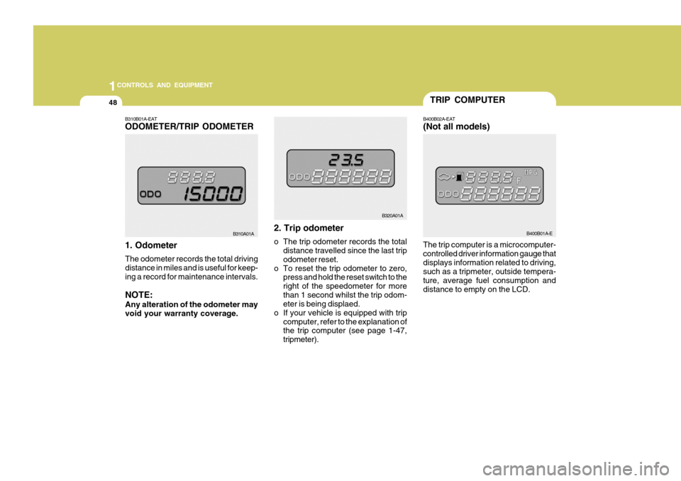
The trip computer is a microcomputer- controlled driver information gauge thatdisplays information related to driving, such as a tripmeter, outside tempera- ture, average fuel consumption anddistance to empty on the LCD.B400B02A-EAT (Not all models)
B400B01A-E
B310B01A-EAT ODOMETER/TRIP ODOMETER 1. Odometer The odometer records the total driving distance in miles and is useful for keep-ing a record for maintenance intervals. NOTE: Any alteration of the odometer may void your warranty coverage. 2. Trip odometer
o The trip odometer records the total
distance travelled since the last trip odometer reset.
o To reset the trip odometer to zero, press and hold the reset switch to theright of the speedometer for morethan 1 second whilst the trip odom- eter is being displaed.
o If your vehicle is equipped with trip
computer, refer to the explanation ofthe trip computer (see page 1-47, tripmeter).
B310A01A
B320A01A
Page 456 of 599
49
1
CONTROLS AND EQUIPMENT
B320A01A
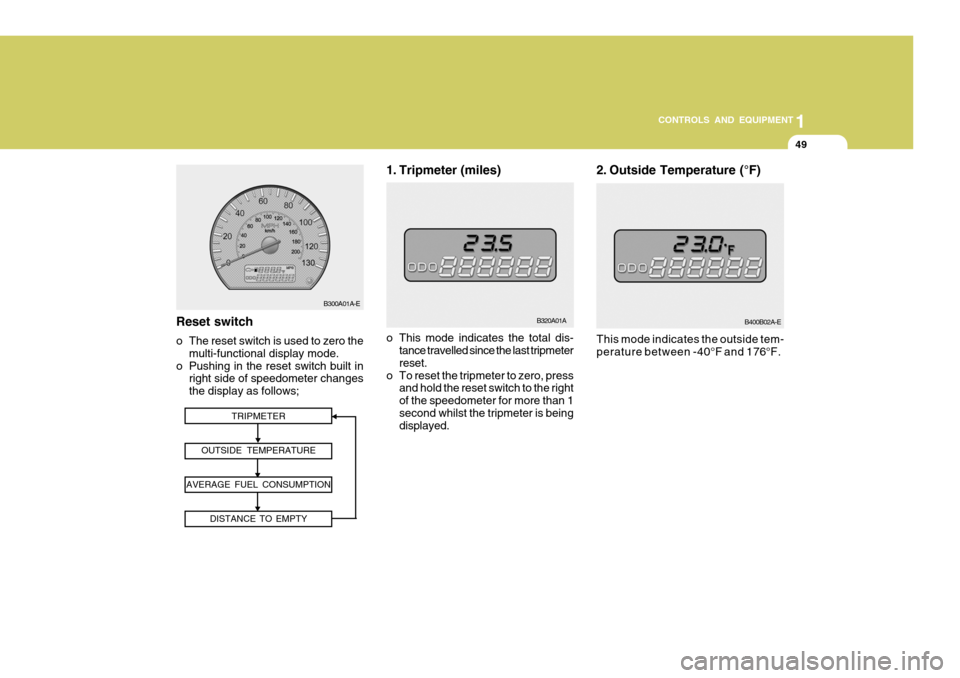
1. Tripmeter (miles)
TRIPMETER
OUTSIDE TEMPERATURE
AVERAGE FUEL CONSUMPTION DISTANCE TO EMPTYReset switch
o The reset switch is used to zero themulti-functional display mode.
o Pushing in the reset switch built in right side of speedometer changes the display as follows; o This mode indicates the total dis-
tance travelled since the last tripmeterreset.
o To reset the tripmeter to zero, press and hold the reset switch to the rightof the speedometer for more than 1second whilst the tripmeter is being displayed.
B300A01A-EB400B02A-E
This mode indicates the outside tem-
perature between -40°F and 176°F.
2. Outside Temperature (°F)
Page 457 of 599
1CONTROLS AND EQUIPMENT
50
B400B03A-E
MPG = Total Cruise Distance(Miles) Total Fuel Consumption (G)
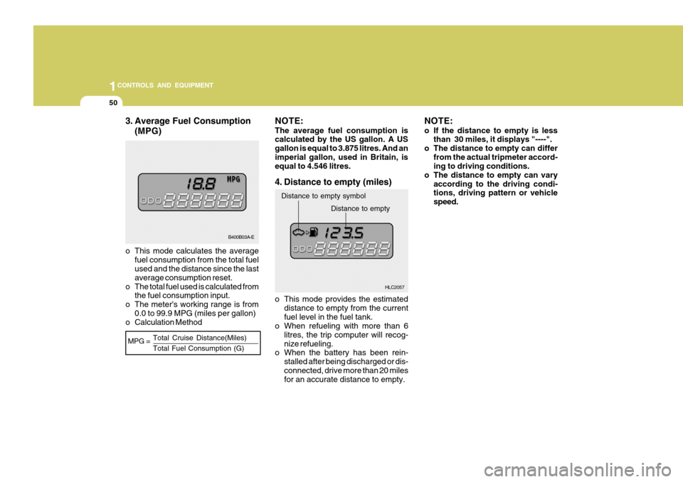
3. Average Fuel Consumption
(MPG)
HLC2057
Distance to empty symbolDistance to empty
o This mode calculates the average fuel consumption from the total fuel used and the distance since the last average consumption reset.
o The total fuel used is calculated from the fuel consumption input.
o The meter's working range is from 0.0 to 99.9 MPG (miles per gallon)
o Calculation Method NOTE: The average fuel consumption is calculated by the US gallon. A US gallon is equal to 3.875 litres. And animperial gallon, used in Britain, is equal to 4.546 litres.
4. Distance to empty (miles)
NOTE:
o If the distance to empty is less than 30 miles, it displays "----".
o The distance to empty can differ from the actual tripmeter accord- ing to driving conditions.
o The distance to empty can vary according to the driving condi-tions, driving pattern or vehicle speed.
o This mode provides the estimated distance to empty from the currentfuel level in the fuel tank.
o When refueling with more than 6
litres, the trip computer will recog-nize refueling.
o When the battery has been rein-
stalled after being discharged or dis-connected, drive more than 20 miles for an accurate distance to empty.
Page 458 of 599
51
1
CONTROLS AND EQUIPMENT
MULTI FUNCTION SWITCH
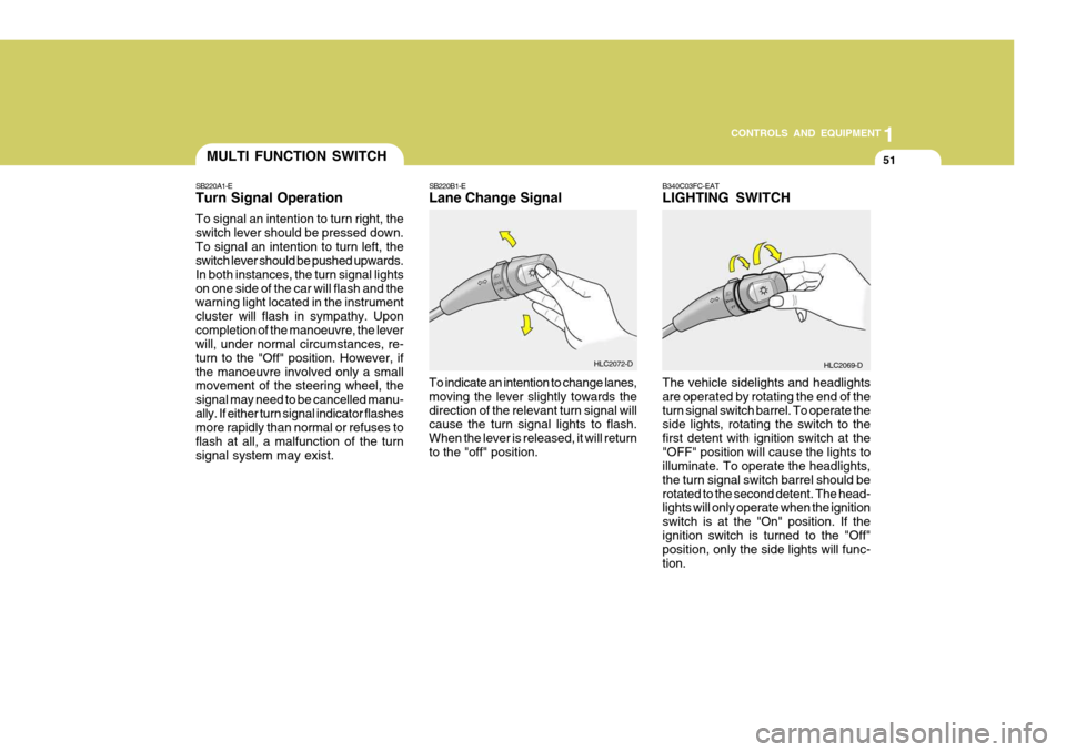
SB220A1-E Turn Signal Operation To signal an intention to turn right, the switch lever should be pressed down.To signal an intention to turn left, the switch lever should be pushed upwards. In both instances, the turn signal lightson one side of the car will flash and the warning light located in the instrument cluster will flash in sympathy. Uponcompletion of the manoeuvre, the lever will, under normal circumstances, re- turn to the "Off" position. However, ifthe manoeuvre involved only a small movement of the steering wheel, the signal may need to be cancelled manu-ally. If either turn signal indicator flashes more rapidly than normal or refuses to flash at all, a malfunction of the turnsignal system may exist. SB220B1-E Lane Change Signal To indicate an intention to change lanes, moving the lever slightly towards thedirection of the relevant turn signal will cause the turn signal lights to flash. When the lever is released, it will returnto the "off" position.
HLC2072-D
HLC2069-D
B340C03FC-EAT LIGHTING SWITCH The vehicle sidelights and headlights are operated by rotating the end of theturn signal switch barrel. To operate the side lights, rotating the switch to the first detent with ignition switch at the"OFF" position will cause the lights to illuminate. To operate the headlights, the turn signal switch barrel should berotated to the second detent. The head- lights will only operate when the ignition switch is at the "On" position. If theignition switch is turned to the "Off" position, only the side lights will func- tion.
Page 459 of 599
1CONTROLS AND EQUIPMENT
52WINDSCREEN WIPER/ WASHER SWITCH
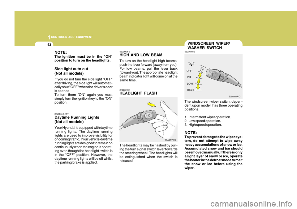
SB230A1-E The windscreen wiper switch, depen- dent upon model, has three operating positions.
1. Intermittent wiper operation.
2. Low speed operation.
3. High speed operation. NOTE: To prevent damage to the wiper sys- tem, do not attempt to wipe away heavy accumulations of snow or ice.Accumulated snow and ice should be removed manually. If there is only a light layer of snow or ice, operatethe heater in the defrost mode to melt the snow or ice before using the wiper.
NOTE: The ignition must be in the "ON" position to turn on the headlights. Side light auto cut (Not all models) If you do not turn the side light "OFF" after driving, the side light will automati- cally shut "OFF" when the driver's door is opened.To turn them "ON" again you must simply turn the ignition key to the "ON" position.
SB220D1-E HIGH AND LOW BEAM To turn on the headlight high beams, push the lever forward (away from you).For low beams, pull the lever back (toward you). The appropriate headlight beam indicator light will come on at thesame time. SB220E1-E HEADLIGHT FLASH The headlights may be flashed by pull- ing the turn signal switch lever towards the steering wheel. The headlights will be extinguished when the switch isreleased.
B340F01A-EAT Daytime Running Lights (Not all models) Your Hyundai is equipped with daytime running lights. The daytime runninglights are used to improve visibility for oncoming traffic. Your vehicle daytime running lights are designed to remain oncontinuously when the engine is operat- ing even though the headlight switch is in the "OFF" position. However, thedaytime running lights will be off whilst the parking brake is applied.
HLC2071-DB350A01A-D
Page 460 of 599
53
1
CONTROLS AND EQUIPMENT
NOTE:
o Do not operate the washer more
than 15 seconds at a time or when the fluid reservoir is empty.
o In icy or freezing weather, be sure the wiper blades are not frozen tothe glass prior to operating thewipers.
o In areas where water freezes in
winter, use windscreen washerantifreeze.
Mist Wiper Operation
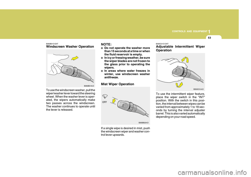
To use the windscreen washer, pull thewiper/washer lever toward the steeringwheel. When the washer lever is oper- ated, the wipers automatically make two passes across the windscreen.The washer continues to operate until the lever is released. B350B01O-EAT Windscreen Washer Operation
If a single wipe is desired in mist, push the windscreen wiper and washer con-trol lever upwards.
B350B01A-D
B350B02A-DB350C01O-DAT Adjustable Intermittent Wiper Operation To use the intermittent wiper feature, place the wiper switch in the "INT" position. With the switch in this posi-tion, the interval between wipes can be varied from approximately 1 to 18 sec- onds by turning the interval adjusterbarrel. This is also varied automatically depending on your road speed.
B350C01A-D