Hyundai Azera 2006 Owner's Manual
Manufacturer: HYUNDAI, Model Year: 2006, Model line: Azera, Model: Hyundai Azera 2006Pages: 307, PDF Size: 12.62 MB
Page 271 of 307
6
DO-IT-YOURSELF MAINTENANCE
34
1
2
3
4
5
6
7
8
9
10
11
12
13
14
15
16
17
18
19
20
21
22
23
24
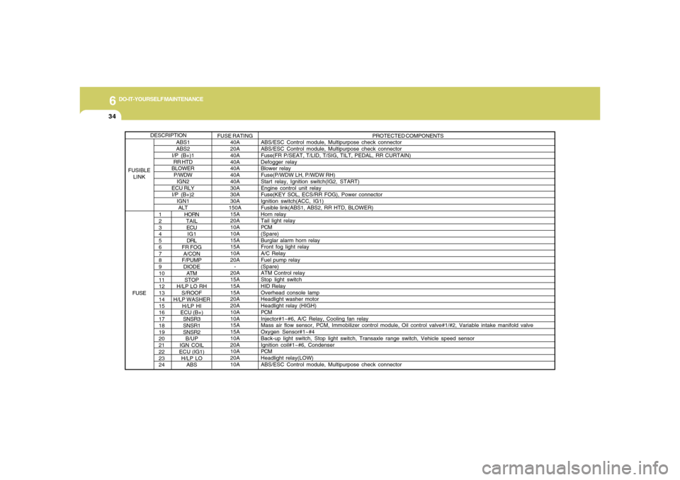
HORN
TAIL
ECU
IG1
DRL
FR FOG
A/CON
F/PUMP
DIODE
ATM
STOP
H/LP LO RH
S/ROOF
H/LP WASHER
H/LP HI
ECU (B+)
SNSR3
SNSR1
SNSR2
B/UP
IGN COIL
ECU (IG1)
H/LP LO
ABSPROTECTED COMPONENTS
ABS/ESC Control module, Multipurpose check connector
ABS/ESC Control module, Multipurpose check connector
Fuse(FR P/SEAT, T/LID, T/SIG, TILT, PEDAL, RR CURTAIN)
Defogger relay
Blower relay
Fuse(P/WDW LH, P/WDW RH)
Start relay, Ignition switch(IG2, START)
Engine control unit relay
Fuse(KEY SOL, ECS/RR FOG), Power connector
Ignition switch(ACC, IG1)
Fusible link(ABS1, ABS2, RR HTD, BLOWER)
Horn relay
Tail light relay
PCM
(Spare)
Burglar alarm horn relay
Front fog light relay
A/C Relay
Fuel pump relay
(Spare)
ATM Control relay
Stop light switch
HID Relay
Overhead console lamp
Headlight washer motor
Headlight relay (HIGH)
PCM
Injector#1~#6, A/C Relay, Cooling fan relay
Mass air flow sensor, PCM, Immobilizer control module, Oil control valve#1/#2, Variable intake manifold valve
Oxygen Sensor#1~#4
Back-up light switch, Stop light switch, Transaxle range switch, Vehicle speed sensor
Ignition coil#1~#6, Condenser
PCM
Headlight relay(LOW)
ABS/ESC Control module, Multipurpose check connector
ABS1
ABS2
I/P (B+)1
RR HTD
BLOWER
P/WDW
IGN2
ECU RLY
I/P (B+)2
IGN1
ALTFUSE RATING
40A
20A
40A
40A
40A
40A
40A
30A
30A
30A
150A
15A
20A
10A
10A
15A
15A
10A
20A
-
20A
15A
15A
15A
20A
20A
10A
10A
15A
15A
10A
20A
10A
20A
10A
DESCRIPTION
FUSIBLE
LINK
FUSE
Page 272 of 307
6
DO-IT-YOURSELF MAINTENANCE
35
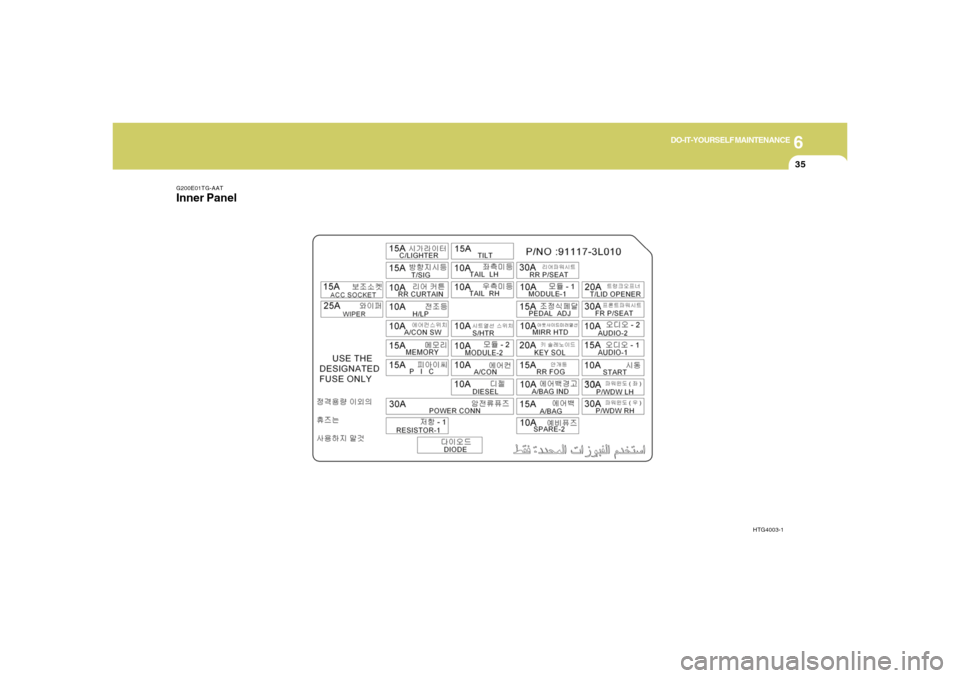
G200E01TG-AATInner Panel
HTG4003-1
Page 273 of 307
6
DO-IT-YOURSELF MAINTENANCE
36
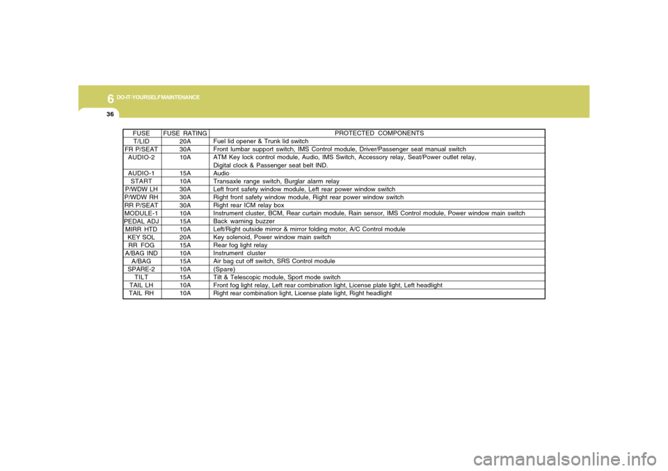
FUSE RATING
20A
30A
10A
15A
10A
30A
30A
30A
10A
15A
10A
20A
15A
10A
15A
10A
15A
10A
10A FUSE
T/LID
FR P/SEAT
AUDIO-2
AUDIO-1
START
P/WDW LH
P/WDW RH
RR P/SEAT
MODULE-1
PEDAL ADJ
MIRR HTD
KEY SOL
RR FOG
A/BAG IND
A/BAG
SPARE-2
TILT
TAIL LH
TAIL RH
PROTECTED COMPONENTS
Fuel lid opener & Trunk lid switch
Front lumbar support switch, IMS Control module, Driver/Passenger seat manual switch
ATM Key lock control module, Audio, IMS Switch, Accessory relay, Seat/Power outlet relay,
Digital clock & Passenger seat belt IND.
Audio
Transaxle range switch, Burglar alarm relay
Left front safety window module, Left rear power window switch
Right front safety window module, Right rear power window switch
Right rear ICM relay box
Instrument cluster, BCM, Rear curtain module, Rain sensor, IMS Control module, Power window main switch
Back warning buzzer
Left/Right outside mirror & mirror folding motor, A/C Control module
Key solenoid, Power window main switch
Rear fog light relay
Instrument cluster
Air bag cut off switch, SRS Control module
(Spare)
Tilt & Telescopic module, Sport mode switch
Front fog light relay, Left rear combination light, License plate light, Left headlight
Right rear combination light, License plate light, Right headlight
Page 274 of 307

6
DO-IT-YOURSELF MAINTENANCE
37
PROTECTED COMPONENTS
Driver seat warmer switch
Instrument cluster, ESC Switch, BCM, ATM Key lock control module, YAW Rate sensor,
Multi-function switch
A/C Control module, Tilt & Telescopic module, Rheostat, Electric chromic mirror, Overhead
console lamp
(Spare)
Cigarette lighter
BCM
Rear curtain module
Headlight relay, AQS & Ambient sensor, HID relay, Headlight leveling actuator
A/C Control module, Blower relay, A/C Control module(AUTO)
Data link connector, A/C Control module, Instrument cluster, Multi-function switch, Tilt &
Telescopic module, BCM, Door warning switch, Room lamp, Left/Right foot lamp, Door lamp
(Spare)
Rear power outlet
Washer relay, Wiper relay(High), Wiper relay
Fuse(MEMORY, AUDIO-1)
FUSE RATING
10A
10A
10A
10A
15A
15A
10A
10A
10A
15A
15A
15A
25A
30A FUSE
S/HTR
MODULE-2
A/CON
DIESEL
C/LIGHTER
T/SIG
RR CURTAIN
H/LP
A/CON SW
MEMORY
PIC
ACC SOCKET
WIPER
POWER CONN
Page 275 of 307

7
Emission Control System ............................................. 7-2
Catalytic Converter ....................................................... 7-3
EMISSION CONTROL SYSTEMS
7
Page 276 of 307

7
EMISSION CONTROL SYSTEMS2
EMISSION CONTROL
SYSTEMS
H010B01A-AAT1. Crankcase Emission Control Sys-
temThe positive crankcase ventilation system
is employed to prevent air pollution caused
by blow-by gases being emitted from the
crankcase. This system supplies fresh fil-
tered air to the crankcase through the air
intake hose. Inside the crankcase, the fresh
air mixes with blow-by gases, which then
pass through the PCV valve into the induc-
tion system.
CanisterFuel vapors generated inside the fuel tank
are absorbed and stored in the onboard
canister. When the engine is running, the
fuel vapors absorbed in the canister are
drawn into the surge tank through the
purge control solenoid valve.Purge Control Solenoid Valve (PCSV)The purge control solenoid valve is con-
trolled by the Engine Control Module
(ECM); when the engine coolant tempera-
ture is low during idling, the PCSV closes
so that evaporated fuel is not taken into the
engine. After the engine warms-up during
ordinary driving, the PCSV opens to intro-
duce evaporated fuel to the engine.H010D01A-AAT3. Exhaust Emission Control
SystemThe Exhaust Emission Control System is a
highly effective system which controls ex-
haust emissions while maintaining good
vehicle performance.
H010A01NF-AATYour Hyundai is equipped with an emis-
sion control system to meet all emission
regulations.
There are three emission control systems
which are as follows.
(1) Crankcase emission control system
(2) Evaporative emission control system
(3) Exhaust emission control system
In order to assure the proper function of the
emission control systems, it is recom-
mended that you have your car inspected
and maintained by an authorized Hyundai
dealer in accordance with the maintenance
schedule in this manual.
Caution for the Inspection and Mainte-
nance Test (With Electronic Stability
Control (ESC) system)
o To prevent the vehicle from misfiring
during dynamometer testing, turn the
Electronic Stability Control (ESC) sys-
tem off by pressing the ESC switch.
o After dynamometer testing is com-
pleted, turn the ESC system back on
by pressing the ESC switch again.
H010C01S-AAT2. Evaporative Emission Control (In-
cluding ORVR: Onboard Refuel-
ing Vapor Recovery) SystemThe Evaporative Emission Control Sys-
tem is designed to prevent fuel vapors from
escaping into the atmosphere.
(The ORVR system is designed to allow
the vapors from the fuel tank to be loaded
into a canister while refueling at the gas
station, preventing the escape of fuel va-
pors into the atmosphere.)
Page 277 of 307
7
EMISSION CONTROL SYSTEMS
3
!
!
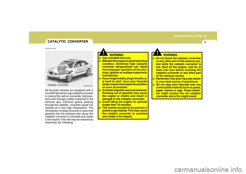
CATALYTIC CONVERTERH020A01A-AATAll Hyundai vehicles are equipped with a
monolith type three-way catalytic converter
to reduce the carbon monoxide, hydrocar-
bons and nitrogen oxides contained in the
exhaust gas. Exhaust gases passing
through the catalytic converter cause it to
operate at a very high temperature. The
introduction of large amounts of unburned
gasoline into the exhaust may cause the
catalytic converter to overheat and create
a fire hazard. This risk may be reduced by
observing the following:Catalytic Converter
WARNING:
o Use unleaded fuel only.
o Maintain the engine in good operating
condition. Extremely high catalytic
converter temperatures can result
from improper operation of the elec-
trical, ignition or multiport electronic
fuel injection.
o If your engine stalls, pings, knocks, or
is hard to start, have your Hyundai
dealer inspect and repair the problem
as soon as possible.
o Avoid driving with a very low fuel level.
Running out of gasoline may cause
the engine to misfire and result in
damage to the catalytic converter.
o Avoid idling the engine for periods
longer than 10 minutes.
o The vehicle should not be pushed or
pulled to get started. This may cause
the catalytic converter to overheat
and create a fire hazard.
H020A01TG
o Do not touch the catalytic converter
or any other part of the exhaust sys-
tem while the catalytic converter is
hot. Shut off the engine, wait for at
least one hour before touching the
catalytic converter or any other part
of the exhaust system.
o Remember that your Hyundai dealer
is your best source of assistance.
o Do not stop your Hyundai over any
combustible material such as grass,
paper, leaves or rags. These materi-
als might contact the hot catalytic
converter and a fire might result.
WARNING:
Page 278 of 307
Vehicle Identification Number (VIN) .............................. 8-2
Engine Number ............................................................. 8-2
Tire Information ............................................................. 8-2
Recommended Cold Tire Inflation Pressures ............... 8-3
Checking Tire Inflation Pressure ................................... 8-5
Tire Sidewall Labeling ................................................... 8-5
Tire Terminology and Definitions ................................... 8-7
All Season Tires ............................................................ 8-9
Snow Tires .................................................................... 8-9
Tire Chains ..................................................................8-10
Tire Rotation................................................................8-10
Tire Balancing.............................................................8-11
Tire Traction................................................................8-11
When to Replace Tires ...............................................8-11
Tire Maintenance........................................................8-12
Spare Tire and Tools ...................................................8-12
Warranties for Your Hyundai Vehicle..........................8-13
Consumer Information.................................................8-13
Reporting Safety Defects............................................8-16
Binding Arbitration of Warranty Claims.......................8-16
8
8
CONSUMER INFORMATION, REPORTING
SAFETY DEFECTS & BINDING
ARBITRATION OF WARRANTY CLAIMS
Page 279 of 307
8
CONSUMER INFORMATION, REPORTING SAFETY DEFECTS & BINDING ARBITRATION OF WARRANTY CLAIMS2
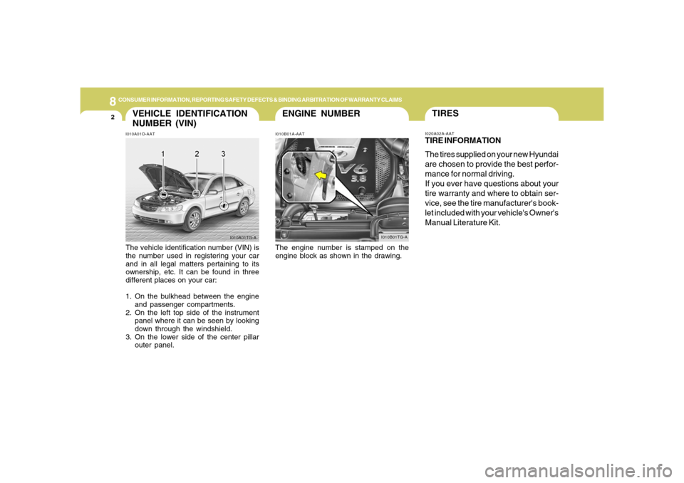
ENGINE NUMBER
VEHICLE IDENTIFICATION
NUMBER (VIN)
I010B01A-AAT I010A01O-AAT
The vehicle identification number (VIN) is
the number used in registering your car
and in all legal matters pertaining to its
ownership, etc. It can be found in three
different places on your car:
1. On the bulkhead between the engine
and passenger compartments.
2. On the left top side of the instrument
panel where it can be seen by looking
down through the windshield.
3. On the lower side of the center pillar
outer panel.The engine number is stamped on the
engine block as shown in the drawing.
TIRESI020A02A-AATTIRE INFORMATION
The tires supplied on your new Hyundai
are chosen to provide the best perfor-
mance for normal driving.
If you ever have questions about your
tire warranty and where to obtain ser-
vice, see the tire manufacturer's book-
let included with your vehicle's Owner's
Manual Literature Kit.
I010A01TG-AI010B01TG-A
Page 280 of 307
8
CONSUMER INFORMATION, REPORTING SAFETY DEFECTS & BINDING ARBITRATION OF WARRANTY CLAIMS
3
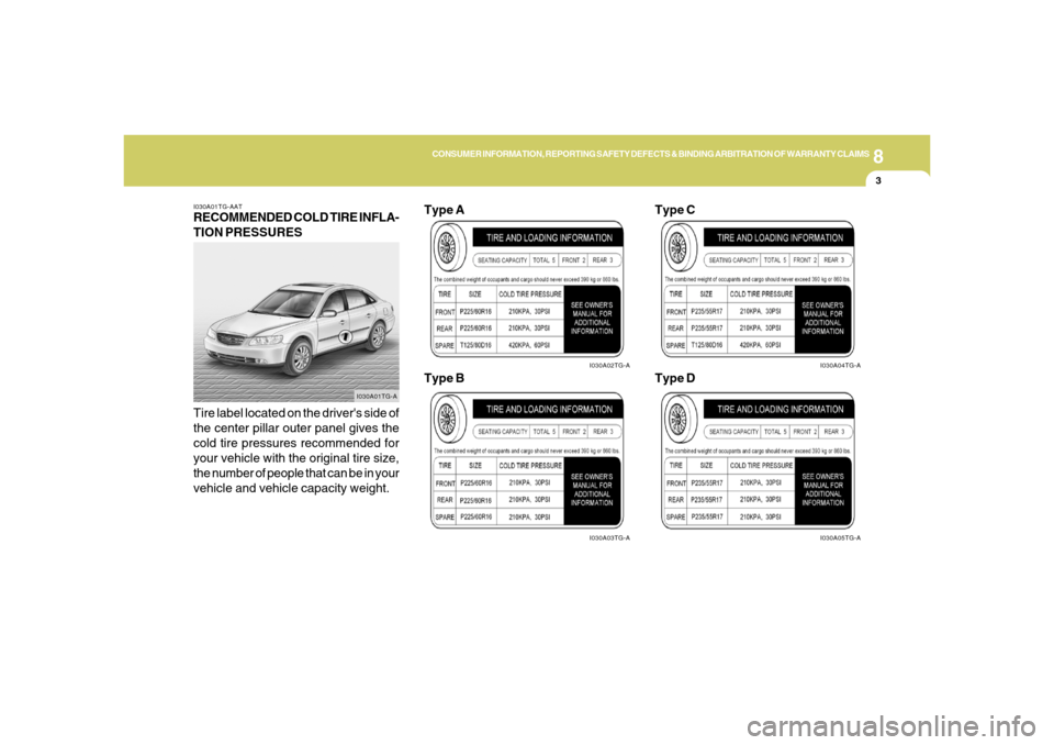
I030A01TG-AATRECOMMENDED COLD TIRE INFLA-
TION PRESSURES
Tire label located on the driver's side of
the center pillar outer panel gives the
cold tire pressures recommended for
your vehicle with the original tire size,
the number of people that can be in your
vehicle and vehicle capacity weight.
I030A01TG-A
I030A02TG-AI030A03TG-A
Type A
Type B
I030A04TG-AI030A05TG-A
Type C
Type D