warning Hyundai Equus 2010 Owner's Manual
[x] Cancel search | Manufacturer: HYUNDAI, Model Year: 2010, Model line: Equus, Model: Hyundai Equus 2010Pages: 374, PDF Size: 41.29 MB
Page 3 of 374
F3
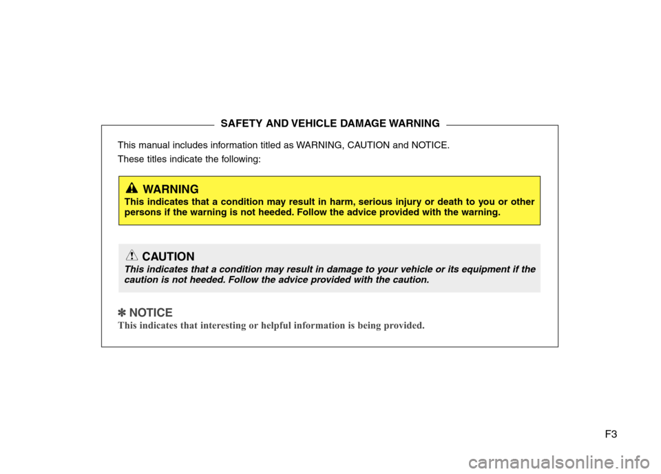
This manual includes information titled as WARNING, CAUTION and NOTICE.
These titles indicate the following:
✽✽
NOTICE
This indicates that interesting or helpful information is being provided.
SAFETY AND VEHICLE DAMAGE WARNING
WARNING
This indicates that a condition may result in harm, serious injury or death to you or other
persons if the warning is not heeded. Follow the advice provided with the warning.
CAUTION
This indicates that a condition may result in damage to your vehicle or its equipment if the caution is not heeded. Follow the advice provided with the caution.
Page 9 of 374
Introduction
2
1
We want to help you get the greatest
possible driving pleasure from your vehi-
cle. Your Owner’s Manual can assist you
in many ways. We strongly recommend
that you read the entire manual. In order
to minimize the chance of death or injury,
you must read the WARNING and CAU-
TION sections in the manual.
Illustrations complement the words in this
manual to best explain how to enjoy your
vehicle. By reading your manual, you
learn about features, important safety
information, and driving tips under vari-
ous road conditions.
The general layout of the manual is pro-
vided in the Table of Contents. A good
place to start is the index; it has an alpha-
betical listing of all information in your
manual.
Sections: This manual has eight sections
plus an index. Each section begins with a
brief list of contents so you can tell at a
glance if that section has the information
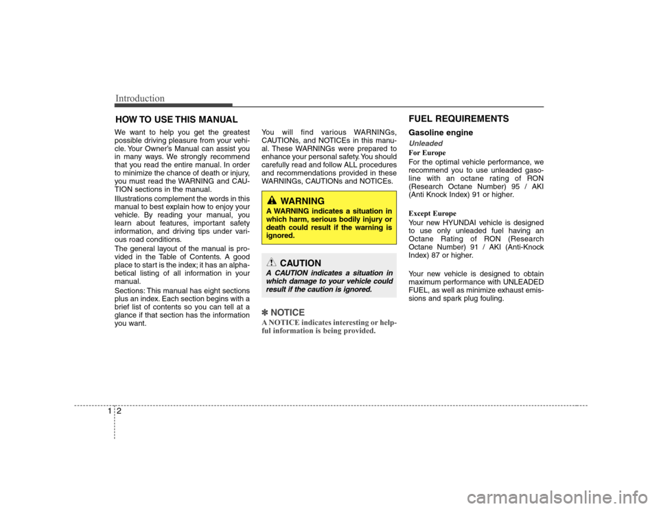
you want. You will find various WARNINGs,
CAUTIONs, and NOTICEs in this manu-
al. These WARNINGs were prepared to
enhance your personal safety. You should
carefully read and follow ALL procedures
and recommendations provided in these
WARNINGs, CAUTIONs and NOTICEs.
✽✽
NOTICE
A NOTICE indicates interesting or help-
ful information is being provided.
Gasoline engine
Unleaded
For Europe
For the optimal vehicle performance, we
recommend you to use unleaded gaso-
line with an octane rating of RON(Research Octane Number) 95 / AKI
(Anti Knock Index) 91 or higher.
Except Europe
Your new HYUNDAI vehicle is designed
to use only unleaded fuel having an
Octane Rating of RON (Research
Octane Number) 91 / AKI (Anti-Knock
Index) 87 or higher.
Your new vehicle is designed to obtain
maximum performance with UNLEADED
FUEL, as well as minimize exhaust emis-
sions and spark plug fouling.
HOW TO USE THIS MANUAL
WARNING
A WARNING indicates a situation in
which harm, serious bodily injury ordeath could result if the warning isignored.
CAUTION
A CAUTION indicates a situation in which damage to your vehicle couldresult if the caution is ignored.
FUEL REQUIREMENTS
Page 10 of 374
13
Introduction
Gasoline containing alcohol andmethanol
Gasohol, a mixture of gasoline and
ethanol (also known as grain alcohol),and gasoline or gasohol containing
methanol (also known as wood alcohol)
are being marketed along with or instead
of leaded gasoline. Do not use gasohol containing more than 10% ethanol, and do not use gasoline or
gasohol containing any methanol. Either
of these fuels may cause drivability prob-lems and damage to the fuel system.
Discontinue using gasohol of any kind if
drivability problems occur.
Vehicle damage or drivability problems
may not be covered by the manufactur-
er’s warranty if they result from the useof:
1. Gasohol containing more than 10% ethanol.
2. Gasoline or gasohol containing methanol.
3. Leaded fuel or leaded gasohol.
Use of MTBE
HYUNDAI recommends avoiding fuels
containing MTBE (Methyl Tertiary Butyl
Ether) over 15.0% vol. (Oxygen Content
2.7% weight) in your vehicle.
Fuel containing MTBE over 15.0% vol.
(Oxygen Content 2.7% weight) may
reduce vehicle performance and produce
vapor lock or hard starting.
WARNING
• Do not "top off" after the nozzle automatically shuts off when refueling.
Always check that the fuel cap is installed securely to prevent fuel
spillage in the event of an acci-dent.
CAUTION
NEVER USE LEADED FUEL. The
use of leaded fuel is detrimental to the catalytic converter and willdamage the engine control sys-
tem’s oxygen sensor and affectemission control.
Never add any fuel system cleaningagents to the fuel tank other thanwhat has been specified. (Consult
an authorized HYUNDAI dealer for details.)
CAUTION
Your New Vehicle Limited Warranty
may not cover damage to the fuelsystem and any performance prob-lems that are caused by the use of
fuels containing methanol or fuels containing MTBE (Methyl TertiaryButyl Ether) over 15.0% vol. (Oxygen Content 2.7% weight.)
CAUTION
Never use gasohol which containsmethanol. Discontinue use of any gasohol product which impairs dri-
vability.
Page 12 of 374
15
Introduction
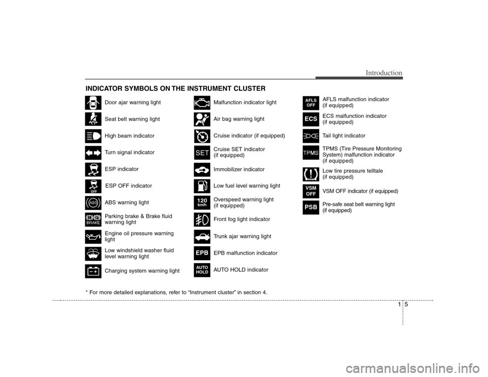
INDICATOR SYMBOLS ON THE INSTRUMENT CLUSTER
Seat belt warning light
High beam indicator
Turn signal indicator
ABS warning light
Parking brake & Brake fluid
warning light
Engine oil pressure warning light
ESP indicator
ESP OFF indicator
Malfunction indicator light
Air bag warning light
Cruise indicator (if equipped)
Cruise SET indicator (if equipped)
Immobilizer indicator
Low fuel level warning light
* For more detailed explanations, refer to “Instrument cluster” in section 4.
Charging system warning light
Low windshield washer fluid
level warning light
Door ajar warning light Overspeed warning light (if equipped)
120km/h
AFLS malfunction indicator (if equipped) ECS malfunction indicator (if equipped)
Tail light indicator
Trunk ajar warning light
Front fog light indicator
AFLSOFF
ECS
EPB malfunction indicator
AUTO HOLD indicator EPB
VSM OFF indicator (if equipped)VSM
OFF
Pre-safe seat belt warning light (if equipped)PSB
AUTO
HOLD
TPMS (Tire Pressure Monitoring System) malfunction indicator(if equipped)
Low tire pressure telltale (if equipped)
Page 13 of 374
Introduction
6
1
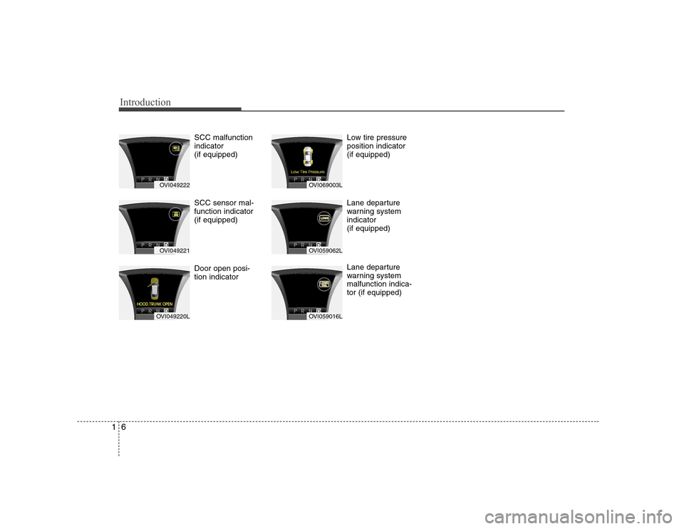
SCC malfunction indicator (if equipped) SCC sensor mal- function indicator (if equipped) Door open posi- tion indicator Low tire pressureposition indicator (if equipped)
Lane departure
warning systemindicator (if equipped)
Lane departure
warning systemmalfunction indica-tor (if equipped)
OVI049222
OVI049221
OVI049220L
OVI069003L
OVI059062L
OVI059016L
Page 16 of 374
23
Your vehicle at a glance
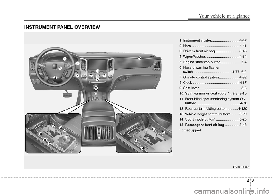
INSTRUMENT PANEL OVERVIEW
1. Instrument cluster.............................4-47
2. Horn .................................................4-41
3. Driver’s front air bag .........................3-48
4. Wiper/Washer ...................................4-84
5. Engine start/stop button .....................5-4
6. Hazard warning flasher switch ........................................4-77, 6-2
7. Climate control system .....................4-92
8. Clock ..............................................4-117
9. Shift lever ...........................................5-8
10. Seat warmer or seat cooler* ...3-8, 3-10
11. Front blind spot monitoring system ON button*.............................................4-76
12. Rear curtain folding button ...........4-120
13. Vehicle height control button* .........5-29
14. Sport mode button* ........................5-28
15. Passenger’s front air bag ...............3-48
* : if equipped
OVI019002L
Page 21 of 374
33
Safety features of your vehicle
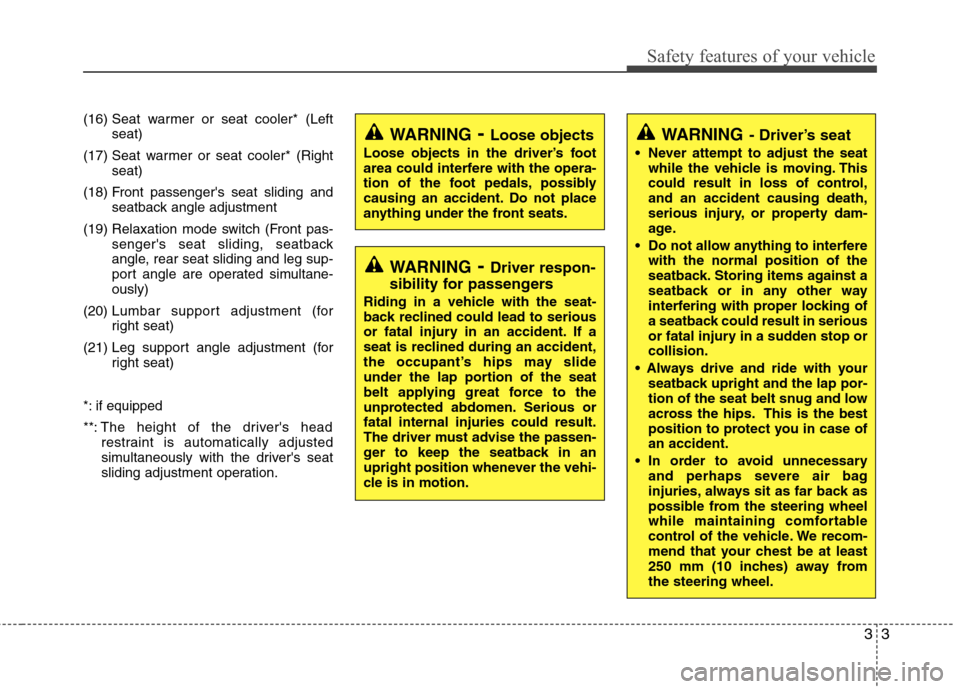
(16) Seat warmer or seat cooler* (Leftseat)
(17) Seat warmer or seat cooler* (Right seat)
(18) Front passenger's seat sliding and seatback angle adjustment
(19) Relaxation mode switch (Front pas- senger's seat sliding, seatback
angle, rear seat sliding and leg sup-
port angle are operated simultane-ously)
(20) Lumbar support adjustment (for
right seat)
(21) Leg support angle adjustment (for right seat)
*: if equipped
**: The height of the driver's headrestraint is automatically adjusted
simultaneously with the driver's seat
sliding adjustment operation.
WARNING - Driver’s seat
Never attempt to adjust the seat while the vehicle is moving. This
could result in loss of control,and an accident causing death,
serious injury, or property dam-
age.
Do not allow anything to interfere with the normal position of the
seatback. Storing items against a
seatback or in any other way
interfering with proper locking of
a seatback could result in serious
or fatal injury in a sudden stop orcollision.
seatback upright and the lap por-
tion of the seat belt snug and low
across the hips. This is the best
position to protect you in case ofan accident.
In order to avoid unnecessary and perhaps severe air bag
injuries, always sit as far back as
possible from the steering wheel
while maintaining comfortable
control of the vehicle. We recom-
mend that your chest be at least
250 mm (10 inches) away fromthe steering wheel.WARNING - Loose objects
Loose objects in the driver’s foot
area could interfere with the opera-
tion of the foot pedals, possibly
causing an accident. Do not place
anything under the front seats.
WARNING - Driver respon-
sibility for passengers
Riding in a vehicle with the seat-
back reclined could lead to serious
or fatal injury in an accident. If a
seat is reclined during an accident,
the occupant’s hips may slide
under the lap portion of the seat
belt applying great force to the
unprotected abdomen. Serious orfatal internal injuries could result.
The driver must advise the passen-
ger to keep the seatback in an
upright position whenever the vehi-
cle is in motion.
Page 22 of 374
Safety features of your vehicle
4
3
Front seat adjustment - power
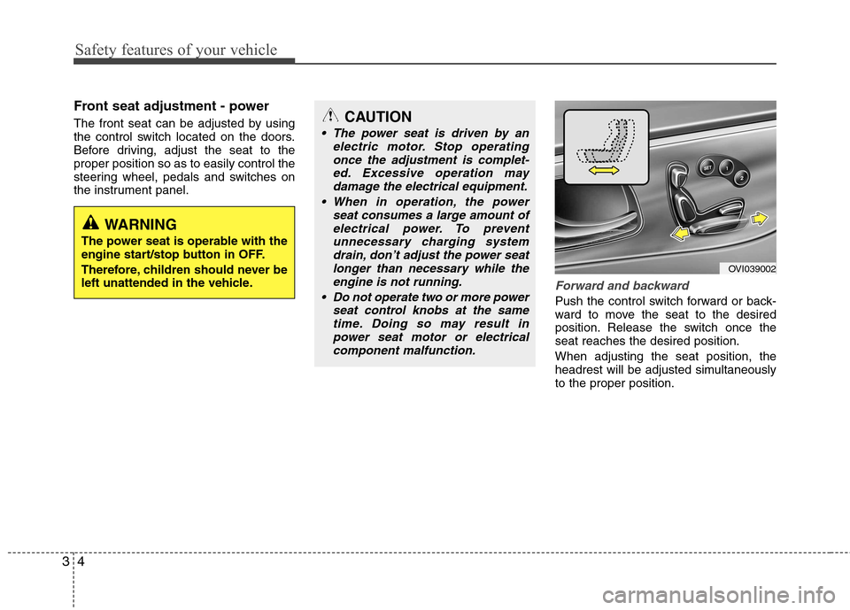
The front seat can be adjusted by using
the control switch located on the doors.
Before driving, adjust the seat to theproper position so as to easily control the
steering wheel, pedals and switches on
the instrument panel.
Forward and backward
Push the control switch forward or back-
ward to move the seat to the desired
position. Release the switch once theseat reaches the desired position. When adjusting the seat position, the
headrest will be adjusted simultaneouslyto the proper position.
OVI039002
CAUTION
The power seat is driven by an
electric motor. Stop operating
once the adjustment is complet-ed. Excessive operation maydamage the electrical equipment.
When in operation, the power seat consumes a large amount ofelectrical power. To preventunnecessary charging systemdrain, don’t adjust the power seat
longer than necessary while the engine is not running.
Do not operate two or more power seat control knobs at the sametime. Doing so may result in
power seat motor or electricalcomponent malfunction.
WARNING
The power seat is operable with the
engine start/stop button in OFF.
Therefore, children should never be
left unattended in the vehicle.
Page 24 of 374
Safety features of your vehicle
6
3
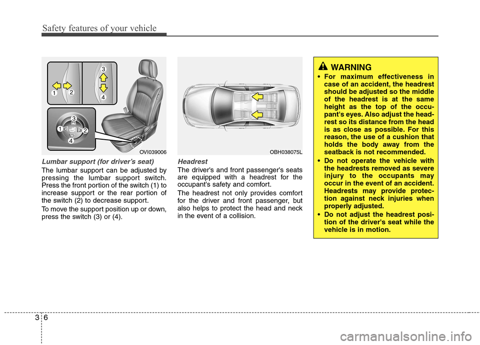
Lumbar support (for driver’s seat)
The lumbar support can be adjusted by
pressing the lumbar support switch.
Press the front portion of the switch (1) to
increase support or the rear portion of
the switch (2) to decrease support.
To move the support position up or down,
press the switch (3) or (4).
Headrest
The driver's and front passenger's seats
are equipped with a headrest for the
occupant's safety and comfort.
The headrest not only provides comfort
for the driver and front passenger, but
also helps to protect the head and neck
in the event of a collision.
WARNING
For maximum effectiveness in case of an accident, the headrest
should be adjusted so the middleof the headrest is at the sameheight as the top of the occu-
pant's eyes. Also adjust the head-
rest so its distance from the head
is as close as possible. For this
reason, the use of a cushion that
holds the body away from the
seatback is not recommended.
Do not operate the vehicle with the headrests removed as severe
injury to the occupants may
occur in the event of an accident.
Headrests may provide protec-
tion against neck injuries when
properly adjusted.
Do not adjust the headrest posi- tion of the driver's seat while the
vehicle is in motion.
OBH038075LOVI039006
Page 25 of 374
37
Safety features of your vehicle
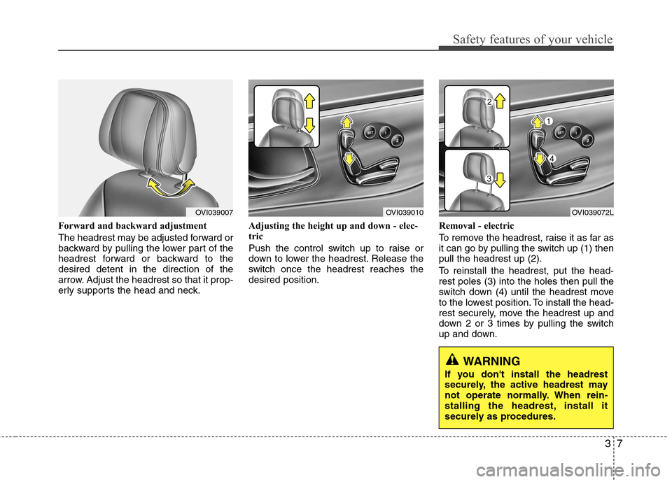
Forward and backward adjustment
The headrest may be adjusted forward or
backward by pulling the lower part of the
headrest forward or backward to thedesired detent in the direction of the
arrow. Adjust the headrest so that it prop-
erly supports the head and neck.Adjusting the height up and down - elec-
tric
Push the control switch up to raise or
down to lower the headrest. Release the
switch once the headrest reaches thedesired position.
Removal - electric
To remove the headrest, raise it as far as
it can go by pulling the switch up (1) thenpull the headrest up (2).
To reinstall the headrest, put the head- rest poles (3) into the holes then pull the
switch down (4) until the headrest move
to the lowest position. To install the head-
rest securely, move the headrest up and
down 2 or 3 times by pulling the switch
up and down.
OVI039010OVI039007OVI039072L
WARNING
If you don't install the headrest
securely, the active headrest may
not operate normally. When rein-
stalling the headrest, install it
securely as procedures.