HYUNDAI GENESIS COUPE 2014 Owners Manual
Manufacturer: HYUNDAI, Model Year: 2014, Model line: GENESIS COUPE, Model: HYUNDAI GENESIS COUPE 2014Pages: 438, PDF Size: 40.35 MB
Page 391 of 438
759
Maintenance
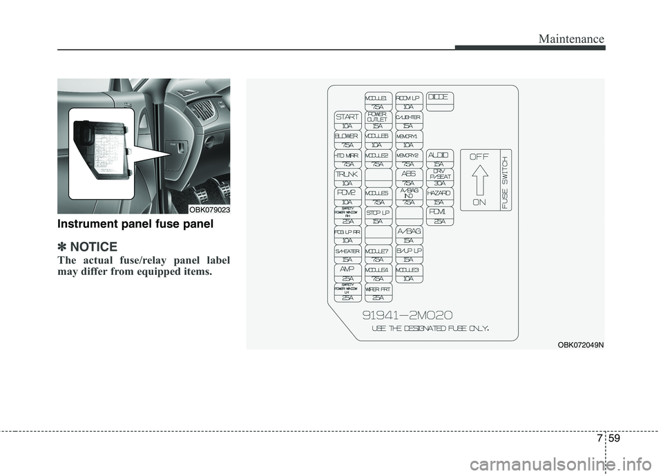
Instrument panel fuse panel
✽ ✽
NOTICE
The actual fuse/relay panel label
may differ from equipped items.
OBK072049N
OBK079023
Page 392 of 438
Maintenance
60 7
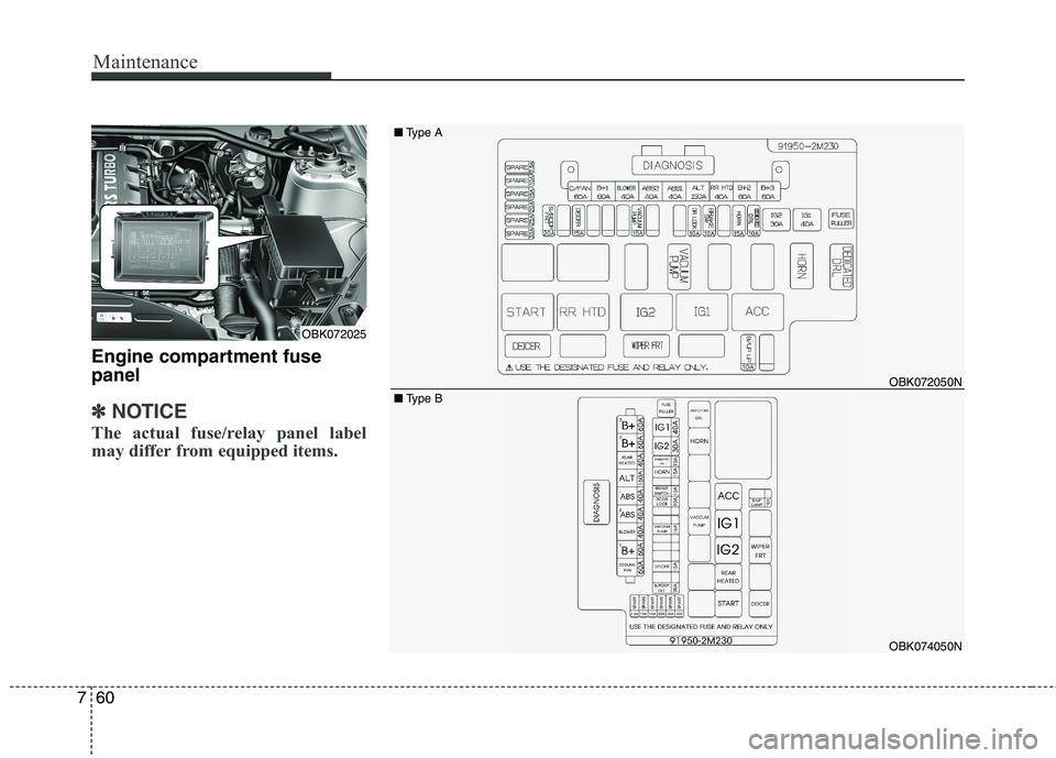
Engine compartment fuse
panel
✽ ✽
NOTICE
The actual fuse/relay panel label
may differ from equipped items.
OBK072050N
OBK074050N
OBK072025■Type A
■Type B
Page 393 of 438

761
Maintenance
Engine compartment fuse
panel
✽ ✽
NOTICE
The actual fuse/relay panel label
may differ from equipped items.
OBK072024
OBK072051N
OBK074051N ■Type A
■Type B
Page 394 of 438

Maintenance
62 7
Instrument panel (Driver’s side fuse panel)
Description Fuse rating Protected component
AUDIO 15AAudio, A/V & Navigation Head Unit, Multi Gauge, Multi Monitor
Front Monitor, MTS Module
DRV P/SEAT 30A Driver Seat Manual Switch, Driver Lumbar Support Switch
HAZARD 15A BCM, Flasher Sound Relay
PDM1 25A PDM
ROOM LP 10ADriver/Passenger Door Lamp, Trunk Room Lamp
Driver/Passenger Door Scuff Lamp, Vanity Lamp LH/RH
Map Lamp
C/LIGHTER 15A Front Power Outlet
MEMORY1 10ABCM, Data Link Connector, Auto Light & Photo Sensor
Ignition Key ILL. & Door Warning Switch, Electro Chromic Mirror
Instrument Cluster (IND. MICOM), A/C Control Module
Tire Pressure Monitoring Module
MEMORY2 7.5A RF Receiver
ABS 7.5AE/R Junction Box LH (Multipurpose Check Connector)
ESC Module, ESC & PAS Switch, Steering Angle Sensor
A/BAG IND 7.5A Instrument Cluster (Air Bag IND.)
A/BAG 15A SRS Control Module, A/C Control Module, PODS Module
B/UP LP 15A Back-Up Lamp Switch, TCM, Transmission Range Switch
MODULE3 10A ECM, PDM, Smart Key Control Module, Injector Drive Box (G6DJ)
MODULE1 7.5AAMP, Audio, A/V & Navigation Head Unit, Multi Monitor, MTS Module
Front Monitor, Map Lamp, Power Outside Mirror Switch
POWER
OUTLET15A Console Power Outlet
MODULE6 10A BCM, PDM, Smart Key Control Module
Page 395 of 438

763
Maintenance
Description Fuse rating Protected component
MODULE2 7.5AIPS Control Module, Instrument Cluster (IND, MICOM), BCM, ATM Shift Lever IND.,
Multifunction Switch (Remote Control), Multi Gauge, Cruise Clutch Pedal Position Switch,
A/C Control Module, Auto Head Lamp Leveling Device Unit, Stop Lamp Switch,
Driver/Passenger Seat Warmer Module, Electro Chromic Mirror, MTS Module,
Tire Pressure Monitoring Module, Head Lamp Leveling Device Actuator LH/RH,
Front Parking Assist Sensor LH/RH
Rear Parking Assist Sensor Side LH/RH
Rear Parking Assist Sensor Center LH/RH
MODULE5 7.5A Sport Mode Switch (A/T), Key Solenoid
STOP LP 15A Stop Signal Relay
MODULE7 7.5A Blower Relay, Sunroof Control Module, A/C Control Module, Cluster Ionizer (Auto A/C)
MODULE4 7.5ABCM, PDM, IPS Control Module, Vacuum Switch
E/R Junction Box LH (Vacuum Pump Relay)
WIPER FRT 25AMultiFunction Switch (Wiper), Front Wiper Motor
E/R Junction Box LH (Wiper FRT Relay)
START 10AE/R Junction Box LH (Start Relay), Ignition Lock Switch, PDM
Transmission Range Switch, ECM (G6DJ), B/Alarm Relay
BLOWER 7.5A A/C Control Module
HTD MIRR 7.5A A/C Control Module, Driver/Passenger Power Outside Mirror
TRUNK 10A Trunk Lid & Fuel Filler Door Switch, ICM Relay Box (Trunk Lid Relay)
PDM2 10A PDM, Smart Key Control Module, Start Stop Button Switch, FOB Holder
SAFETY POWER
WINDOW RH25A Passenger Safety Power Window Module
FOG LP RR 10A (Not Used)
S/HEATER 15A Driver/Passenger Seat Warmer Module
AMP 25A AMP (JBL)
SAFETY POWER
WINDOW LH25A Driver Safety Power Window Module
Page 396 of 438
Maintenance
64 7
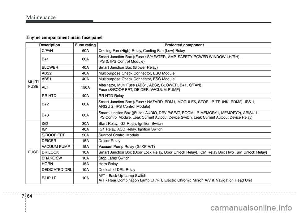
Engine compartment main fuse panel
Description Fuse rating Protected component
MULTI
FUSEC/FAN 60A Cooling Fan (High) Relay, Cooling Fan (Low) Relay
B+1 60ASmart Junction Box ((Fuse : S/HEATER, AMP, SAFETY POWER WINDOW LH/RH),
IPS 2, IPS Control Module)
BLOWER 40A Smart Junction Box (Blower Relay)
ABS2 40A Multipurpose Check Connector, ESC Module
ABS1 40A Multipurpose Check Connector, ESC Module
ALT 150AAlternator, Multi Fuse (ABS1, ABS2, BLOWER, B+1, C/FAN),
Fuse (S/ROOF FRT, DEICER, VACUUM PUMP)
RR HTD 40A RR HTD Relay
B+260ASmart Junction Box ((Fuse : HAZARD, PDM1, MODULE5, STOP LP, TRUNK, PDM2), IPS 1,
ARISU 2, IPS Control Module)
B+360ASmart Junction Box ((Fuse : AUDIO, DRV P/SEAT, ROOM LP, MEMORY1, MEMORY2), ARISU 1,
IPS Control Module, Leak Current Autocut Device Switch, Leak Current Autocut Device Relay)
FUSEIG2 30A Start Relay, IG2 Relay, Ignition Switch
IG140AIG1 Relay, ACC Relay, Ignition Switch
S/ROOF FRT 20A Sunroof Control Module
DEICER 15A Deicer Relay
VACUUM PUMP 15A Vacuum Pump Relay (G4KF A/T)
DR LOCK 10A Smart Junction Box (Door Lock Relay, Door Unlock Relay), ICM Relay Box (Two Turn Unlock Relay)
BRAKE SW 10A Stop Lamp Switch
HORN 15A Horn Relay
DEDICATED DRL 10A Dedicated DRL Relay
B/UP LP 10AM/T - Back-Up Lamp Switch
A/T - Rear Combination Lamp LH/RH, Electro Chromic Mirror, A/V & Navigation Head Unit
Page 397 of 438
765
Maintenance
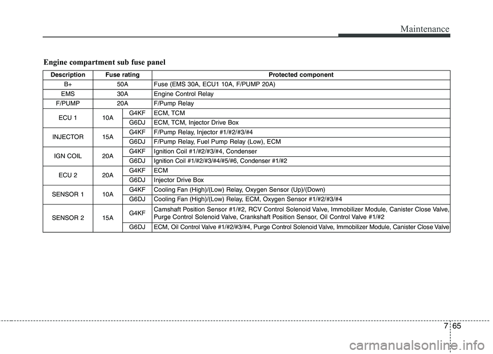
Engine compartment sub fuse panel
Description Fuse rating Protected component
B+ 50A Fuse (EMS 30A, ECU1 10A, F/PUMP 20A)
EMS 30A Engine Control Relay
F/PUMP 20A F/Pump Relay
ECU 1 10AG4KF ECM, TCM
G6DJ ECM, TCM, Injector Drive Box
INJECTOR 15AG4KF F/Pump Relay, Injector #1/#2/#3/#4
G6DJ F/Pump Relay, Fuel Pump Relay (Low), ECM
IGN COIL20AG4KFIgnition Coil #1/#2/#3/#4, Condenser
G6DJIgnition Coil #1/#2/#3/#4/#5/#6, Condenser #1/#2
ECU 2 20AG4KF ECM
G6DJInjector Drive Box
SENSOR 1 10AG4KF Cooling Fan (High)/(Low) Relay, Oxygen Sensor (Up)/(Down)
G6DJ Cooling Fan (High)/(Low) Relay, ECM, Oxygen Sensor #1/#2/#3/#4
SENSOR 2 15AG4KFCamshaft Position Sensor #1/#2, RCV Control Solenoid Valve, Immobilizer Module, Canister Close Valve,
Purge Control Solenoid Valve, Crankshaft Position Sensor, Oil Control Valve #1/#2
G6DJECM, Oil Control Valve #1/#2/#3/#4, Purge Control Solenoid Valve, Immobilizer Module, Canister Close Valve
Page 398 of 438

Maintenance
66 7
LIGHT BULBS
Use only the bulbs of the specified
wattage.
✽ ✽
NOTICE
After heavy, driving rain or washing,
headlight and taillight lenses could
appear frosty. This condition is
caused by the temperature difference
between the lamp inside and outside.
This is similar to the condensation on
your windows inside your vehicle
during the rain and doesn’t indicate
a problem with your vehicle. If the
water leaks into the lamp bulb cir-
cuitry, have the vehicle checked by
an authorized HYUNDAI dealer.WARNING - Working on
the lights
Prior to working on the light,
firmly apply the parking brake,
ensure that the ignition switch
is turned to the LOCK position
and turn off the lights to avoid
sudden movement of the vehi-
cle and burning your fingers or
receiving an electric shock.
CAUTION
Be sure to replace the burned-
out bulb with one of the same
wattage rating. Otherwise, it
may cause damage to the fuse
or electric wiring system.
CAUTION
If you don’t have necessary
tools, the correct bulbs and the
expertise, consult an authorized
HYUNDAI dealer. In many cases,
it is difficult to replace vehicle
light bulbs because other parts
of the vehicle must be removed
before you can get to the bulb.
This is especially true if you
have to remove the headlight
assembly to
get to the bulb(s).
Removing/installing
the head-
light assembly can result in
damage to the vehicle.
Page 399 of 438
767
Maintenance
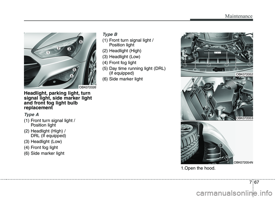
Headlight, parking light, turn
signal light, side marker light
and front fog light bulb
replacement
Ty p e A
(1) Front turn signal light /
Position light
(2) Headlight (High) /
DRL (If equipped)
(3) Headlight (Low)
(4) Front fog light
(6) Side marker light
Type B
(1) Front turn signal light /
Position light
(2) Headlight (High)
(3) Headlight (Low)
(4) Front fog light
(5) Day time running light (DRL)
(if equipped)
(6) Side marker light
1.Open the hood.
OBK072052
OBK072053
OBK072054N
OBK072026
Page 400 of 438
Maintenance
68 7
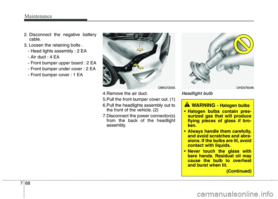
2. Disconnect the negative battery
cable.
3. Loosen the retaining bolts .
- Head lights assembly : 2 EA
- Air duct : 4 EA
- Front bumper upper board : 2 EA
- Front bumper under cover : 2 EA
- Front bumper cover : 1 EA
4.Remove the air duct.
5.Pull the front bumper cover out. (1)
6.Pull the headlights assembly out to
the front of the vehicle. (2)
7.Disconnect the power connector(s)
from the back of the headlight
assembly.
Headlight bulb
OHD076046
WARNING- Halogen bulbs
Halogen bulbs contain pres-
surized gas that will produce
flying pieces of glass if bro-
ken.
Always handle them carefully,
and avoid scratches and abra-
sions. If the bulbs are lit, avoid
contact with liquids.
Never touch the glass with
bare hands. Residual oil may
cause the bulb to overheat
and burst when lit.
(Continued)
OBK072055