lamp HYUNDAI I10 2011 Owners Manual
[x] Cancel search | Manufacturer: HYUNDAI, Model Year: 2011, Model line: I10, Model: HYUNDAI I10 2011Pages: 354, PDF Size: 37.04 MB
Page 15 of 354
Your vehicle at a glance
2
2
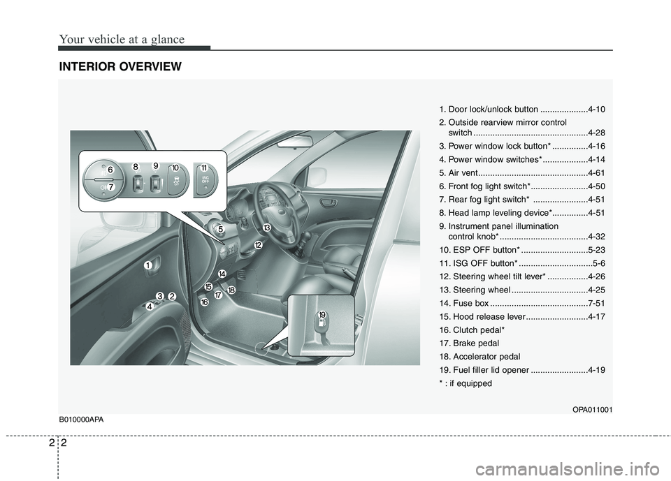
INTERIOR OVERVIEW
1. Door lock/unlock button ....................4-10
2. Outside rearview mirror control
switch ................................................4-28
3. Power window lock button* ...............4-16
4. Power window switches* ...................4-14
5. Air vent ..............................................4-61
6. Front fog light switch*........................4-50
7. Rear fog light switch* .......................4-51
8. Head lamp leveling device*...............4-51
9. Instrument panel illumination control knob* .....................................4-32
10. ESP OFF button* ............................5-23
11. ISG OFF button* ...............................5-6
12. Steering wheel tilt lever* .................4-26
13. Steering wheel ................................4-25
14. Fuse box .........................................7-51
15. Hood release lever ..........................4-17
16. Clutch pedal*
17. Brake pedal
18. Accelerator pedal
19. Fuel filler lid opener ........................4-19
* : if equipped
OPA011001
B010000APA
Page 127 of 354
Features of your vehicle
48
4
D190100AUN
Battery saver function (if equipped)
The purpose of this feature is to pre-
vent the battery from being dis-
charged. The system automatically
turns off the exterior lights when the
driver removes the ignition key and
opens the driver-side door.
With this feature, the parking lights will be turned off automatically if the driver
parks on the side of road at night.
If necessary, to keep the lights on
when the ignition key is removed, per-
form the following:
1) Open the driver-side door.
2) Turn the parking lights OFF and ON again using the light switch on the
steering column. D190400AUN
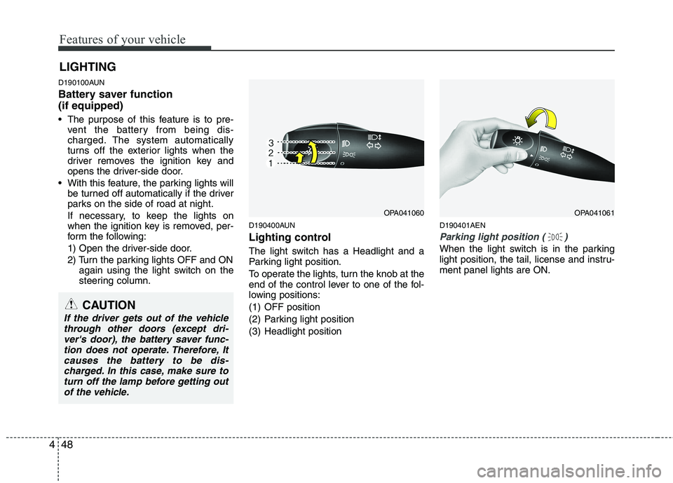
Lighting control
The light switch has a Headlight and a
Parking light position.
To operate the lights, turn the knob at the
end of the control lever to one of the fol-
lowing positions:
(1) OFF position
(2) Parking light position
(3) Headlight position D190401AEN
Parking light position ( )
When the light switch is in the parking
light position, the tail, license and instru-ment panel lights are ON.
LIGHTING
OPA041060OPA041061
CAUTION
If the driver gets out of the vehicle
through other doors (except dri-ver's door), the battery saver func-tion does not operate. Therefore, Itcauses the battery to be dis-
charged. In this case, make sure toturn off the lamp before getting out of the vehicle.
Page 134 of 354
455
Features of your vehicle
D210000AEN
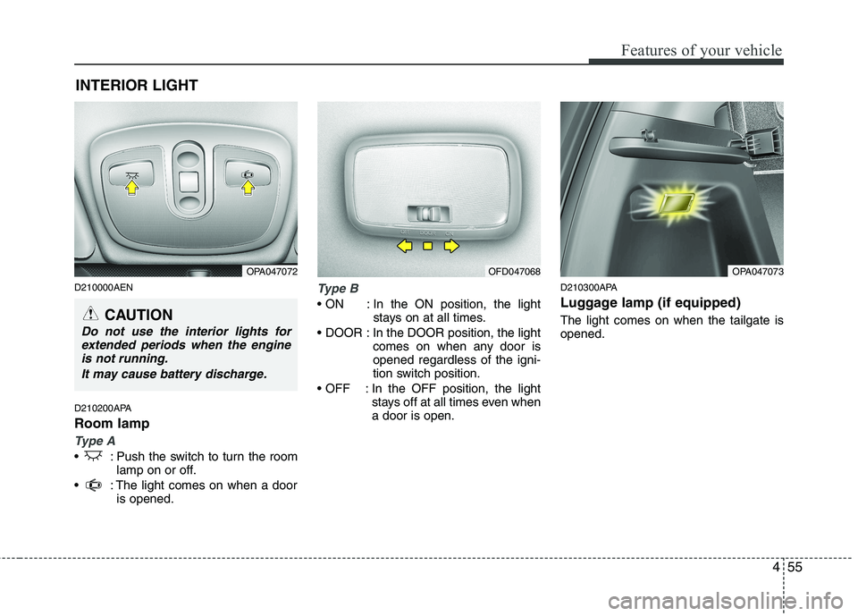
D210200APA Room lamp
Type A
: Push the switch to turn the roomlamp on or off.
: The light comes on when a door is opened.
Type B
In the ON position, the light stays on at all times.
In the DOOR position, the light comes on when any door is opened regardless of the igni-
tion switch position.
In the OFF position, the light stays off at all times even whena door is open. D210300APA
Luggage lamp (if equipped) The light comes on when the tailgate is opened.
INTERIOR LIGHT
CAUTION
Do not use the interior lights for
extended periods when the engineis not running.
It may cause battery discharge.
OPA047072OPA047073OFD047068
Page 156 of 354
477
Features of your vehicle
✽✽NOTICE
If you install an aftermarket HID head
lamp, your vehicle’s audio and electron-
ic device may malfunction.
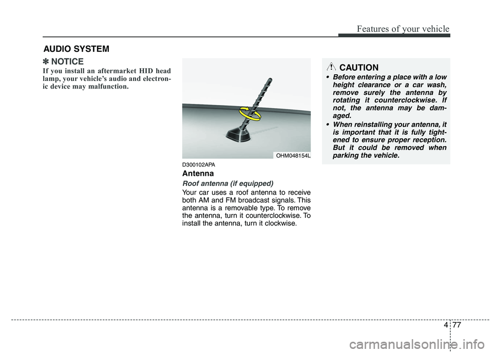
D300102APA Antenna
Roof antenna (if equipped)
Your car uses a roof antenna to receive
both AM and FM broadcast signals. This
antenna is a removable type. To remove
the antenna, turn it counterclockwise. To
install the antenna, turn it clockwise.
AUDIO SYSTEM
OHM048154L
CAUTION
• Before entering a place with a low
height clearance or a car wash,
remove surely the antenna by rotating it counterclockwise. Ifnot, the antenna may be dam-aged.
When reinstalling your antenna, it is important that it is fully tight-ened to ensure proper reception. But it could be removed when
parking the vehicle.
Page 196 of 354
Driving your vehicle
4
5
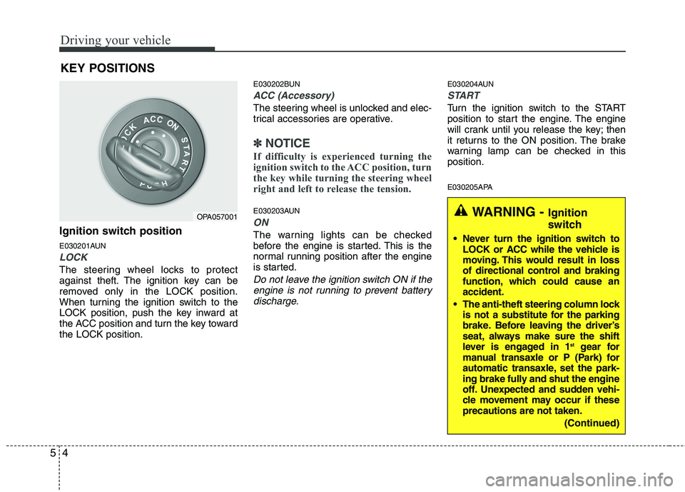
Ignition switch position
E030201AUN
LOCK
The steering wheel locks to protect
against theft. The ignition key can be
removed only in the LOCK position.
When turning the ignition switch to the
LOCK position, push the key inward at
the ACC position and turn the key towardthe LOCK position. E030202BUN
ACC (Accessory)
The steering wheel is unlocked and elec-
trical accessories are operative.
✽✽
NOTICE
If difficulty is experienced turning the
ignition switch to the ACC position, turn
the key while turning the steering wheel
right and left to release the tension.
E030203AUN
ON
The warning lights can be checked
before the engine is started. This is the
normal running position after the engine
is started.
Do not leave the ignition switch ON if the engine is not running to prevent battery
discharge.
E030204AUN
START
Turn the ignition switch to the START
position to start the engine. The engine
will crank until you release the key; then
it returns to the ON position. The brake
warning lamp can be checked in thisposition.
E030205APA
KEY POSITIONS
OPA057001WARNING -
Ignition
switch
Never turn the ignition switch to LOCK or ACC while the vehicle is
moving. This would result in loss
of directional control and braking
function, which could cause anaccident.
The anti-theft steering column lock is not a substitute for the parking
brake. Before leaving the driver’s
seat, always make sure the shift
lever is engaged in 1 st
gear for
manual transaxle or P (Park) for
automatic transaxle, set the park-
ing brake fully and shut the engine
off. Unexpected and sudden vehi-
cle movement may occur if theseprecautions are not taken.
(Continued)
Page 270 of 354
Maintenance
8
7
G030103AUN
At least monthly:
Check coolant level in the engine
coolant reservoir.
Check the operation of all exterior lights, including the stoplights, turn sig-
nals and hazard warning flashers.
Check the inflation pressures of all tires including the spare. G030104AUN
At least twice a year
(i.e., every Spring and Fall):
Check radiator, heater and air condi- tioning hoses for leaks or damage.
Check windshield washer spray and wiper operation. Clean wiper blades
with clean cloth dampened with wash-er fluid.
Check headlight alignment.
Check muffler, exhaust pipes, shields and clamps.
Check the lap/shoulder belts for wear and function.
Check for worn tires and loose wheel lug nuts. G030105APA
At least once a year:
Clean body and door drain holes.
Lubricate door hinges and checks, and
hood hinges.
Lubricate door and hood locks and latches.
Lubricate door rubber weatherstrips.
Check the air conditioning system.
Inspect and lubricate automatic transaxle linkage and controls.
Clean battery and terminals.
Check the brake/clutch fluid level.
Page 285 of 354
723
Maintenance
G050600AUN
Vapor hose and fuel filler cap
The vapor hose and fuel filler cap should
be inspected at those intervals specified
in the maintenance schedule. Make sure
that a new vapor hose or fuel filler cap iscorrectly replaced.
G050700AUN
Vacuum crankcase ventilation hoses (if equipped)
Inspect the surface of hoses for evidence
of heat and/or mechanical damage. Hard
and brittle rubber, cracking, tears, cuts,
abrasions, and excessive swelling indi-
cate deterioration. Particular attention
should be paid to examine those hose
surfaces nearest to high heat sources,
such as the exhaust manifold. Inspect the hose routing to assure that the hoses do not come in contact with
any heat source, sharp edges or movingcomponent which might cause heat dam-
age or mechanical wear. Inspect all hose
connections, such as clamps and cou-
plings, to make sure they are secure, and
that no leaks are present. Hoses should
be replaced immediately if there is any
evidence of deterioration or damage.G050800AEN
Air cleaner filter
A Genuine HYUNDAI air cleaner filter is recommended when the filter isreplaced.
G050900AUN Spark plugs
Make sure to install new spark plugs of
the correct heat range. G051000AEN
Valve clearance (if equipped)
Inspect excessive valve noise and/or
engine vibration and adjust if necessary.
An authorized HYUNDAI dealer should
perform the operation.
G051100AUN Cooling system
Check cooling system components, such
as radiator, coolant reservoir, hoses and
connections for leakage and damage.
Replace any damaged parts.
G051200AUN Coolant The coolant should be changed at the
intervals specified in the maintenance
schedule.
G051300AUN
Manual transaxle fluid (if equipped)
Inspect the manual transaxle fluid
according to the maintenance schedule.
G051400AUN
Automatic transaxle fluid (if equipped)
The fluid level should be in the "HOT"
range of the dipstick, after the engine
and transaxle are at normal operating
temperature. Check the automatic
transaxle fluid level with the engine run-
ning and the transaxle in neutral, with the
parking brake properly applied.
G051500AUN Brake hoses and lines
Visually check for proper installation,
chafing, cracks, deterioration and any
leakage. Replace any deteriorated or
damaged parts immediately.
Page 286 of 354
Maintenance
24
7
G051600AUN Brake fluid
Check brake fluid level in the brake fluid
reservoir. The level should be between
“MIN” and “MAX” marks on the side of
the reservoir. Use only hydraulic brake
fluid conforming to DOT 3 or DOT 4specification.
G051700AUN
Parking brake
Inspect the parking brake system includ-
ing the parking brake pedal and cables.
G051800APA Rear brake drums and linings
Check the rear brake drums and linings
for scoring, burning, leaking fluid, broken
parts, and excessive wear.
G051900AUN
Brake discs, pads, calipers and
rotors
Check the pads for excessive wear, discs
for run out and wear, and calipers for fluid
leakage. G052000APA
Exhaust pipe and muffler
Visually inspect the exhaust pipes, muf-
fler and hangers for cracks, deterioration,
or damage. Start the engine and listen
carefully for any exhaust gas leakage.
Tighten connections or replace parts as
necessary.
G052100AUN Suspension mounting bolts
Check the suspension connections for
looseness or damage. Retighten to the
specified torque.
G052200AUN
Steering gear box, linkage &
boots/lower arm ball joint
With the vehicle stopped and engine off,
check for excessive free-play in the
steering wheel.
Check the linkage for bends or damage.
Check the dust boots and ball joints for
deterioration, cracks, or damage.
Replace any damaged parts.
G052400APA Drive shafts and boots
Check the drive shafts, boots and clamps
for cracks, deterioration, or damage.
Replace any damaged parts and, if nec-
essary, repack the specified grease.
Consult an authorized HYUNDAI dealer
for details.
G052500AUN
Air conditioning refrigerant (if equipped)
Check the air conditioning lines and con-
nections for leakage and damage.
Page 302 of 354
Maintenance
40
7
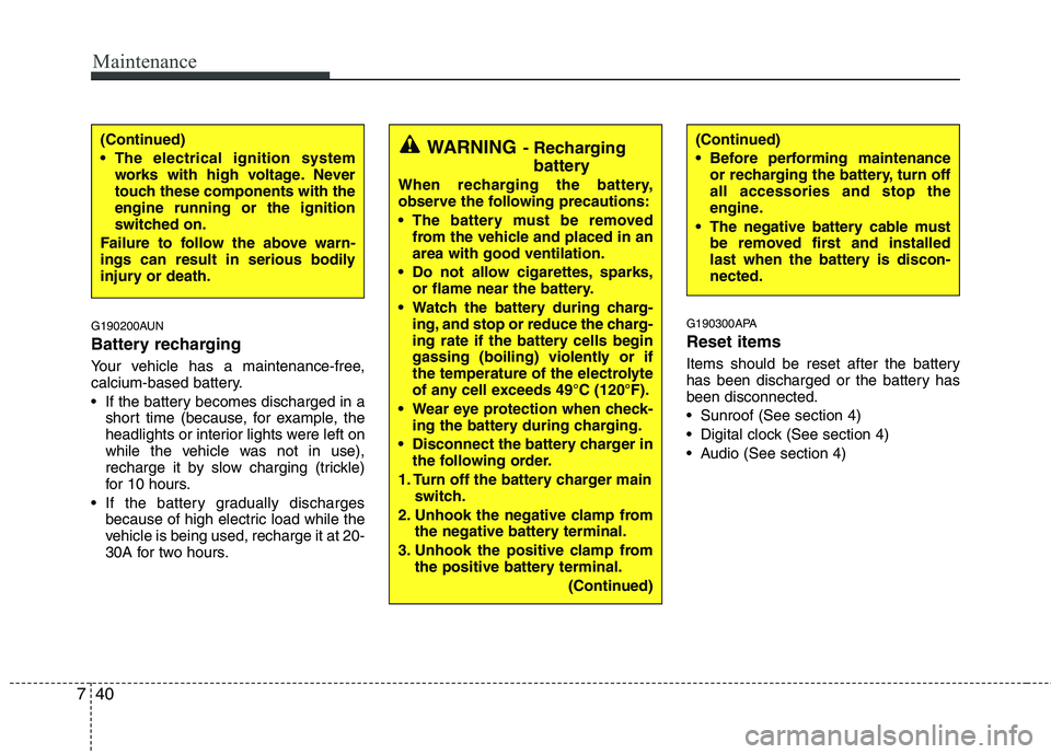
G190200AUN
Battery recharging
Your vehicle has a maintenance-free,
calcium-based battery.
If the battery becomes discharged in a
short time (because, for example, the
headlights or interior lights were left on
while the vehicle was not in use),
recharge it by slow charging (trickle)
for 10 hours.
If the battery gradually discharges because of high electric load while the
vehicle is being used, recharge it at 20-
30A for two hours. G190300APA Reset items
Items should be reset after the battery
has been discharged or the battery hasbeen disconnected.
Sunroof (See section 4)
Digital clock (See section 4)
Audio (See section 4)
(Continued)
The electrical ignition system
works with high voltage. Never
touch these components with theengine running or the ignition
switched on.
Failure to follow the above warn-
ings can result in serious bodily
injury or death.(Continued)
Before performing maintenance or recharging the battery, turn off all accessories and stop the
engine.
The negative battery cable must be removed first and installed
last when the battery is discon-nected.WARNING - Recharging
battery
When recharging the battery,
observe the following precautions:
The battery must be removed from the vehicle and placed in an area with good ventilation.
Do not allow cigarettes, sparks, or flame near the battery.
Watch the battery during charg- ing, and stop or reduce the charg-
ing rate if the battery cells begin
gassing (boiling) violently or if
the temperature of the electrolyte
of any cell exceeds 49°C (120°F).
Wear eye protection when check- ing the battery during charging.
Disconnect the battery charger in the following order.
1. Turn off the battery charger main switch.
2. Unhook the negative clamp from the negative battery terminal.
3. Unhook the positive clamp from the positive battery terminal.
(Continued)
Page 315 of 354
753
Maintenance
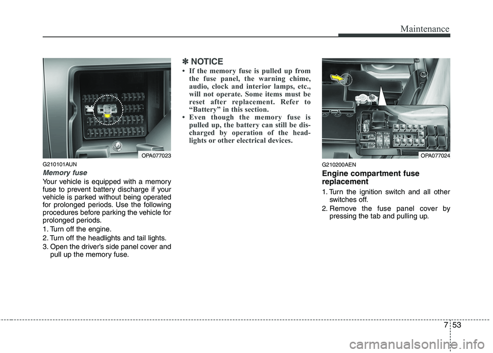
G210101AUN
Memory fuse
Your vehicle is equipped with a memory
fuse to prevent battery discharge if your
vehicle is parked without being operated
for prolonged periods. Use the following
procedures before parking the vehicle for
prolonged periods.
1. Turn off the engine.
2. Turn off the headlights and tail lights.
3. Open the driver’s side panel cover andpull up the memory fuse.
✽✽ NOTICE
If the memory fuse is pulled up from the fuse panel, the warning chime,
audio, clock and interior lamps, etc.,
will not operate. Some items must be
reset after replacement. Refer to
“Battery” in this section.
Even though the memory fuse is
pulled up, the battery can still be dis-
charged by operation of the head-
lights or other electrical devices.
G210200AEN
Engine compartment fuse replacement
1. Turn the ignition switch and all other switches off.
2. Remove the fuse panel cover by pressing the tab and pulling up.
OPA077023OPA077024