fuel filter HYUNDAI IX35 2011 Owners Manual
[x] Cancel search | Manufacturer: HYUNDAI, Model Year: 2011, Model line: IX35, Model: HYUNDAI IX35 2011Pages: 560, PDF Size: 28.31 MB
Page 6 of 560
Introduction
6
1
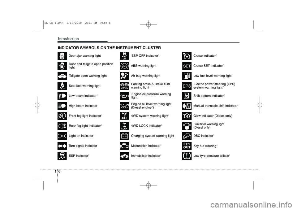
INDICATOR SYMBOLS ON THE INSTRUMENT CLUSTER
Engine oil pressure warning light
Seat belt warning light
Door and tailgate open position light
High beam indicator
Light on indicator*
Turn signal indicator
ABS warning light
Parking brake & Brake fluid
warning light
4WD system warning light* 4WD LOCK indicator*
Malfunction indicator*
Air bag warning light
Cruise SET indicator*
Low fuel level warning light
Charging system warning light
Door ajar warning light
Glow indicator (Diesel only)
Fuel filter warning light (Diesel only)
Cruise indicator*
ESP indicator*
ESP OFF indicator*
Immobiliser indicator*
Shift pattern indicator*
Front fog light indicator*
Rear fog light indicator*
Low beam indicator*
Electric power steering (EPS)
system warning light*
Key out warning*
KEY
OUT
DBC indicator*
Tailgate open warning light
Engine oil level warning light (Diesel engine*)
Low tyre pressure telltale*
Manual transaxle shift indicator*
EL UK 1.QXP 1/12/2010 2:51 PM Page 6
Page 12 of 560
25
Your vehicle at a glance
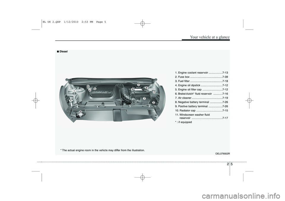
OEL079002R
1. Engine coolant reservoir ..................7-13
2. Fuse box ..........................................7-39
3. Fuel filter ..........................................7-18
4. Engine oil dipstick ............................7-12
5. Engine oil filler cap ..........................7-12
6. Brake/clutch* fluid reservoir ............7-16
7. Air cleaner ........................................7-19
8. Negative battery terminal ................7-26
9. Positive battery terminal ..................7-26
10. Radiator cap ..................................7-15
11. Windscreen washer fluid reservoir ........................................7-17
* : if equipped
■■Diesel
* The actual engine room in the vehicle may differ from the illustration.
EL UK 2.QXP 1/12/2010 2:53 PM Page 5
Page 136 of 560
461
Features of your vehicle
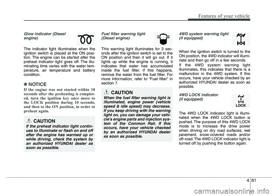
Glow indicator (Dieselengine)
The indicator light illuminates when the
ignition switch is placed at the ON posi-
tion. The engine can be started after the
preheat indicator light goes off. The illu-
minating time varies with the water tem-
perature, air temperature and batterycondition.
✽✽ NOTICE
If the engine was not started within 10
seconds after the preheating is complet-
ed, turn the ignition key once more to
the LOCK position during 10 seconds,
and then to the ON position, in order to
preheat again.
Fuel filter warning light (Diesel engine)
This warning light illuminates for 3 sec-
onds after the ignition switch is set to the
ON position and then it will go out. If it
lights up while the engine is running, it
indicates that water has accumulated
inside the fuel filter. If this happens,
remove the water from the fuel filter. For
more Information, refer to “Fuel filter” insection 7.
4WD system warning light(if equipped)
When the ignition switch is turned to the ON position, the 4WD indicator will illumi-
nate and then go off in a few seconds.
If the 4WD system warning light
illuminates, this indicates that there is a
malfunction in the 4WD system. If this
occurs, have your vehicle checked by an
authorized HYUNDAI dealer as soon as
possible.
4WD LOCK indicator (if equipped)
The 4WD LOCK indicator light is illumi-
nated when the 4WD LOCK button is
pushed. The purpose of this 4WD LOCK
mode is to increase the drive power
when driving on dry road surfaces, wet
pavement, snow-covered roads and/or
off-road. The 4WD LOCK indicator light is
turned off by pushing the button again.
CAUTION
When the fuel filter warning light is
illuminated, engine power (vehicle speed & idle speed) may decrease.If you keep driving with the warninglight on, you can damage your vehi-
cle's engine parts and injection sys-tem of the Common Rail. If thisoccurs, have your vehicle checkedby an authorized HYUNDAI dealer
as soon as possible.
CAUTION
If the preheat indicator light contin- ues to illuminate or flash on and off
after the engine has warmed up orwhile driving, check the system byan authorized HYUNDAI dealer as soon as possible.
Page 321 of 560
7
Engine compartment / 7-2 Maintenance services / 7-4
Owner maintenance / 7-6Scheduled maintenance service / 7-8Explanation of scheduled maintenance items / 7-19Engine oil / 7-12Engine coolant / 7-13Brake/clutch fluid / 7-16
Washer fluid / 7-17Parking brake / 7-17
Fuel filter / 7-18
Air cleaner / 7-19
Climate control air filter / 7-21
Wiper blades / 7-23Battery / 7-26
Tyres and wheels / 7-29 Fuses / 7-39 Light bulbs / 7-49
Appearance care / 7-57
Emission control system / 7-63
Maintenance
EL UK 7.QXP 1/25/2010 10:00 AM Page 1
Page 323 of 560
73
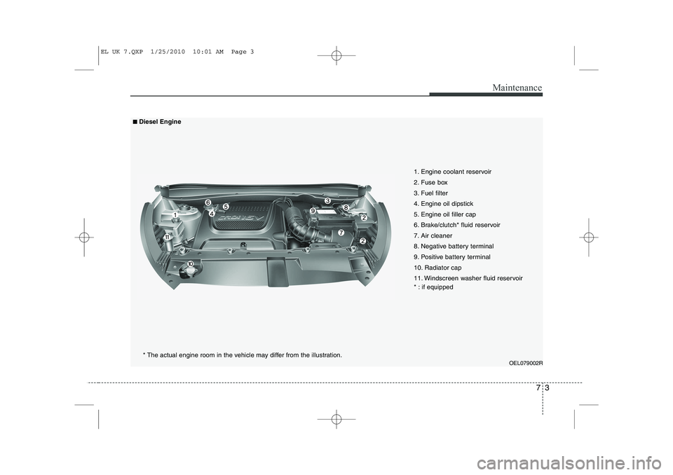
Maintenance
OEL079002R
1. Engine coolant reservoir
2. Fuse box
3. Fuel filter
4. Engine oil dipstick
5. Engine oil filler cap
6. Brake/clutch* fluid reservoir
7. Air cleaner
8. Negative battery terminal
9. Positive battery terminal
10. Radiator cap
11. Windscreen washer fluid reservoir
* : if equipped
■■Diesel Engine
* The actual engine room in the vehicle may differ from the illustration.
EL UK 7.QXP 1/25/2010 10:01 AM Page 3
Page 329 of 560
79
Maintenance
EXPLANATION OF SCHEDULED MAINTENANCE ITEMS
Engine oil and filter The engine oil and filter should be
changed at the intervals specified in the
maintenance schedule. If the car is being
driven in severe conditions, more fre-quent oil and filter changes are required. Drive belts
Inspect all drive belts for evidence of
cuts, cracks, excessive wear or oil satu-
ration and replace if necessary. Drive
belts should be checked periodically forproper tension and adjusted as neces-
sary. Fuel filter (cartridge) A clogged filter can limit the speed at
which the vehicle may be driven, damage
the emission system and cause multiple
issues such as hard starting. If an exces-
sive amount of foreign matter accumu-
lates in the fuel tank, the filter may
require replacement more frequently.
After installing a new filter, run the engine
for several minutes, and check for leaks
at the connections. Fuel filters should be
installed by a HYUNDAI authorised
repairer.
Fuel lines, fuel hoses and con- nections
Check the fuel lines, fuel hoses and con-
nections for leakage and damage. Have
a HYUNDAI authorised repairer replace
any damaged or leaking parts immedi-
ately.
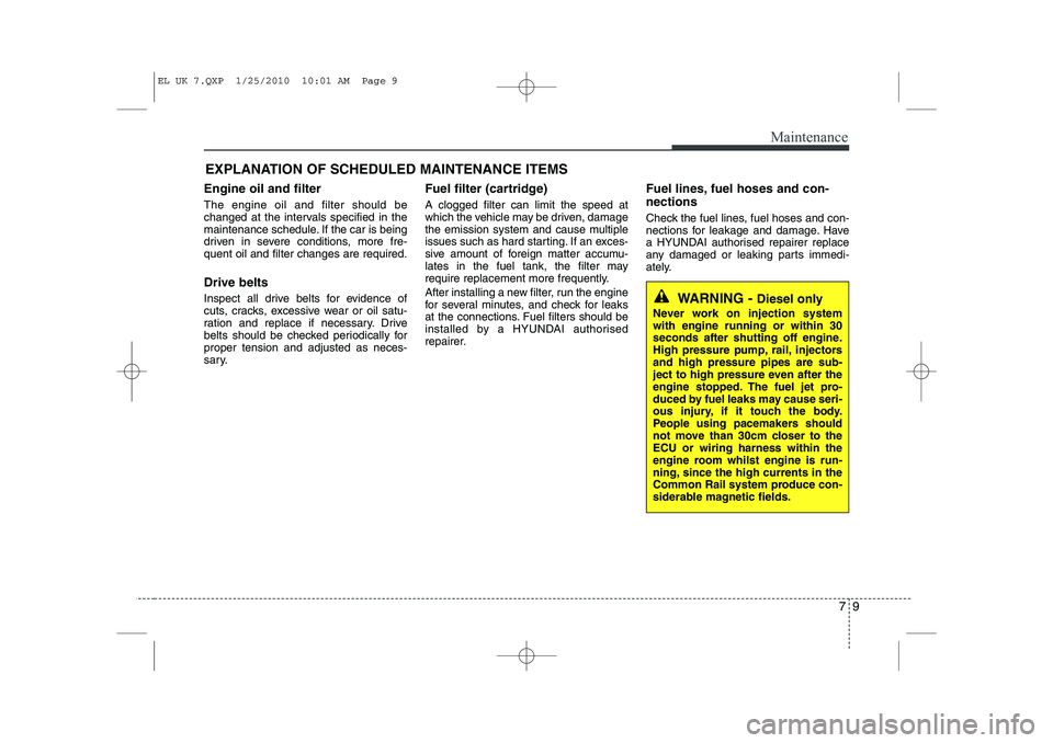
WARNING -
Diesel only
Never work on injection system with engine running or within 30
seconds after shutting off engine.
High pressure pump, rail, injectorsand high pressure pipes are sub-
ject to high pressure even after the
engine stopped. The fuel jet pro-
duced by fuel leaks may cause seri-
ous injury, if it touch the body.
People using pacemakers should
not move than 30cm closer to theECU or wiring harness within the
engine room whilst engine is run-
ning, since the high currents in the
Common Rail system produce con-
siderable magnetic fields.
EL UK 7.QXP 1/25/2010 10:01 AM Page 9
Page 330 of 560
Maintenance
10
7
Vapour hose and fuel filler cap
The vapour hose and fuel filler cap
should be inspected at those intervals
specified in the maintenance schedule.
Make sure that a new vapour hose or fuelfiller cap is correctly replaced.
Vacuum crankcase ventilation hoses (if equipped)
Inspect the surface of hoses for evidence
of heat and/or mechanical damage. Hard
and brittle rubber, cracking, tears, cuts,
abrasions, and excessive swelling indi-
cate deterioration. Particular attention
should be paid to examine those hose
surfaces nearest to high heat sources,
such as the exhaust manifold. Inspect the hose routing to assure that the hoses do not come in contact with
any heat source, sharp edges or movingcomponent which might cause heat dam-
age or mechanical wear. Inspect all hose
connections, such as clamps and cou-
plings, to make sure they are secure, and
that no leaks are present. Hoses should
be replaced immediately if there is any
evidence of deterioration or damage. Air cleaner filter
A Genuine HYUNDAI air cleaner filter is recommended when the filter is replaced.
Spark plugs (for petrol engine)
Make sure to install new spark plugs of
the correct heat range.
Valve clearance
(for petrol engine)
Inspect excessive valve noise and/or
engine vibration and adjust if necessary.
A HYUNDAI authorised repairer should
perform the operation. Cooling system
Check the cooling system parts, such as
radiator, coolant reservoir, hoses and
connections for leakage and damage.
Replace any damaged parts.
Coolant The coolant should be changed at the
intervals specified in the maintenance
schedule.
Manual transaxle fluid (if equipped)
Inspect the manual transaxle fluid
according to the maintenance schedule.
Automatic transaxle fluid (if equipped)
Automatic transaxle fluid should not be
checked under normal usage conditions.
But in severe conditions, the fluid should
be changed at a HYUNDAI authorisedrepairer in accordance to the sched-uled maintenance at the beginning of this
chapter.
✽✽
NOTICE
Automatic transaxle fluid colour is basi-
cally red. As the vehicle is driven, the automatic
transaxle fluid will begin to look darker.It is normal condition and you should
not judge the need to replace the fluid
based upon the changed colour.
EL UK 7.QXP 1/25/2010 10:01 AM Page 10
Page 338 of 560
Maintenance
18
7
FUEL FILTER (FOR DIESEL)
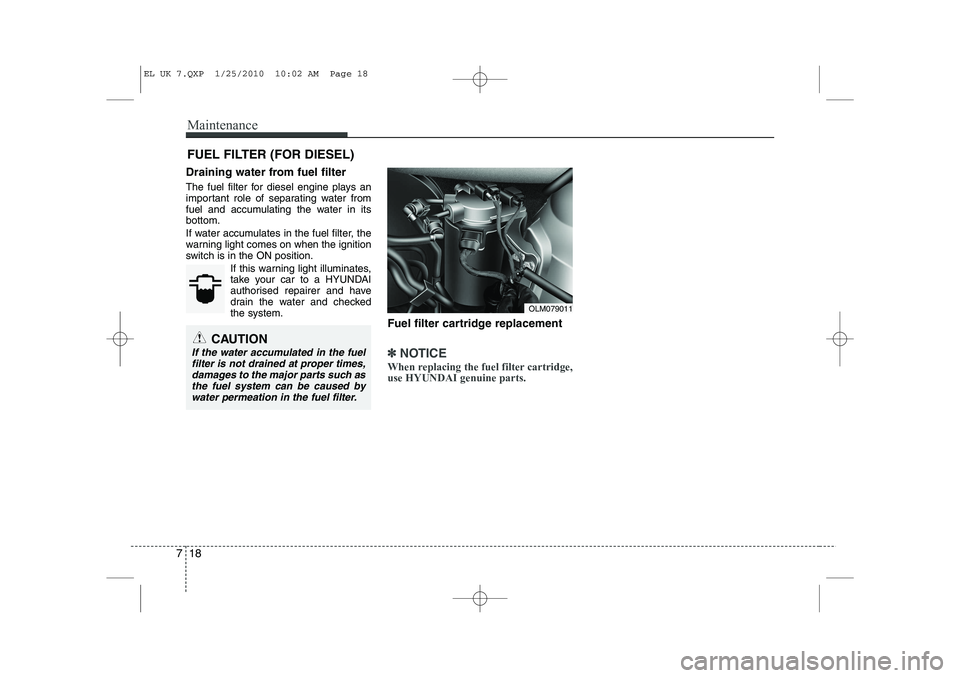
Draining water from fuel filter
The fuel filter for diesel engine plays an
important role of separating water from
fuel and accumulating the water in itsbottom.
If water accumulates in the fuel filter, the
warning light comes on when the ignition
switch is in the ON position. If this warning light illuminates,
take your car to a HYUNDAI
authorised repairer and have
drain the water and checkedthe system. Fuel filter cartridge replacement
✽✽NOTICE
When replacing the fuel filter cartridge, use HYUNDAI genuine parts.
OLM079011
CAUTION
If the water accumulated in the fuel filter is not drained at proper times,
damages to the major parts such asthe fuel system can be caused by water permeation in the fuel filter.
EL UK 7.QXP 1/25/2010 10:02 AM Page 18
Page 368 of 560
Maintenance
48
7
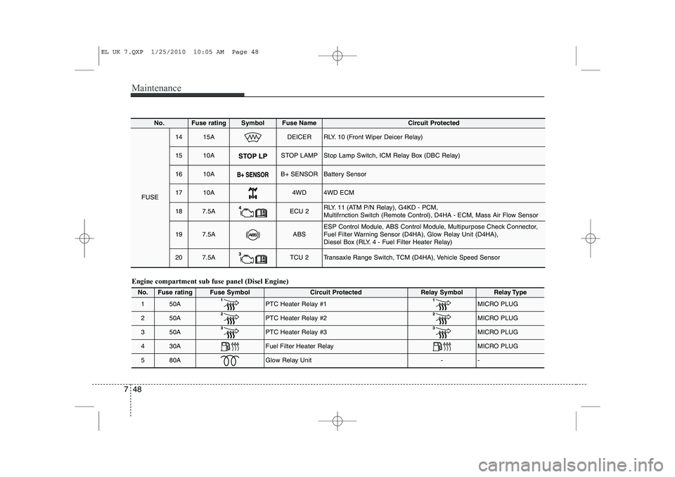
Engine compartment sub fuse panel (Disel Engine)
No.Fuse ratingFuse SymbolCircuit ProtectedRelay SymbolRelay Type
150APTC Heater Relay #1 MICRO PLUG
250APTC Heater Relay #2MICRO PLUG
350APTC Heater Relay #3 MICRO PLUG
430AFuel Filter Heater Relay MICRO PLUG
580AGlow Relay Unit--
No.Fuse ratingSymbolFuse Name Circuit Protected
FUSE
1415ADEICERRLY. 10 (Front Wiper Deicer Relay)
1510ASTOP LAMPStop Lamp Switch, ICM Relay Box (DBC Relay)
1610AB+ SENSORBattery Sensor
1710A4WD4WD ECM
187.5AECU 2RLY. 11 (ATM P/N Relay), G4KD - PCM,
Multifrnction Switch (Remote Control), D4HA - ECM, Mass Air Flow Sensor
197.5AABSESP Control Module, ABS Control Module, Multipurpose Check Connector,
Fuel Filter Warning Sensor (D4HA), Glow Relay Unit (D4HA),
Diesel Box (RLY. 4 - Fuel Filter Heater Relay)
207.5ATCU 2Transaxle Range Switch, TCM (D4HA), Vehicle Speed Sensor
EL UK 7.QXP 1/25/2010 10:05 AM Page 48
Page 383 of 560
763
Maintenance
EMISSION CONTROL SYSTEM
The emission control system of your
vehicle is covered by a written limited
warranty. Please see the warranty infor-
mation contained in the Service Passport
in your vehicle.
Your vehicle is equipped with an emis- sion control system to meet all emission
regulations. There are three emission control sys-
tems which are as follows.
(1) Crankcase emission control system
(2) Evaporative emission control system(3) Exhaust emission control system In order to assure the proper function of
the emission control systems, it is rec-
ommended that you have your car
inspected and maintained by a
HYUNDAI authorised repairer in accor-
dance with the maintenance schedule. Caution for the Inspection and
Maintenance Test (With Electronic
Stability Program (ESP) system)
To prevent the vehicle from misfir-
ing during dynamometer testing,
turn the Electronic Stability
Program (ESP) system off by press-
ing the ESP switch.
After dynamometer testing is com- pleted, turn the ESP system back on
by pressing the ESP switch again.
1. Crankcase emission control system
The positive crankcase ventilation sys-
tem is employed to prevent air pollution
caused by blow-by gases being emitted
from the crankcase. This system supplies
fresh filtered air to the crankcase through
the air intake hose. Inside the crankcase,
the fresh air mixes with blow-by gases,
which then pass through the PCV valveinto the induction system. 2. Evaporative emission control
System
The Evaporative Emission Control
System is designed to prevent fuel
vapours from escaping into the atmos-
phere.
Canister
Fuel vapours generated inside the fuel tank are absorbed and stored in the
onboard canister. When the engine is
running, the fuel vapours absorbed in the
canister are drawn into the surge tank
through the purge control solenoid valve.
Purge Control Solenoid Valve (PCSV)
The purge control solenoid valve is con-
trolled by the Engine Control Module
(ECM); when the engine coolant temper-
ature is low during idling, the PCSV clos-
es so that evaporated fuel is not taken
into the engine. After the engine warms-
up during ordinary driving, the PCSV
opens to introduce evaporated fuel to the
engine.
EL UK 7.QXP 1/25/2010 10:06 AM Page 63