display INFINITI M 2012 Owners Manual
[x] Cancel search | Manufacturer: INFINITI, Model Year: 2012, Model line: M, Model: INFINITI M 2012Pages: 522, PDF Size: 3.8 MB
Page 15 of 522
0-8Illustrated table of contents
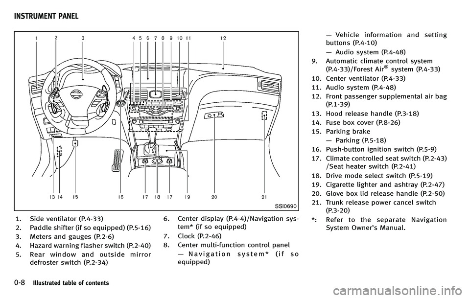
SSI0690
1. Side ventilator (P.4-33)
2. Paddle shifter (if so equipped) (P.5-16)
3. Meters and gauges (P.2-6)
4. Hazard warning flasher switch (P.2-40)
5. Rear window and outside mirrordefroster switch (P.2-34) 6. Center display (P.4-4)/Navigation sys-
tem* (if so equipped)
7. Clock (P.2-46)
8. Center multi-function control panel —Navigation system* (if so
equipped) —
Vehicle information and setting
buttons (P.4-10)
— Audio system (P.4-48)
9. Automatic climate control system (P.4-33)/Forest Air
®system (P.4-33)
10. Center ventilator (P.4-33)
11. Audio system (P.4-48)
12. Front passenger supplemental air bag (P.1-39)
13. Hood release handle (P.3-18)
14. Fuse box cover (P.8-26)
15. Parking brake —Parking (P.5-18)
16. Push-button ignition switch (P.5-9)
17. Climate controlled seat switch (P.2-43) /Seat heater switch (P.2-41)
18. Drive mode select switch (P.5-19)
19. Cigarette lighter and ashtray (P.2-47)
20. Glove box lid release handle (P.2-50)
21. Trunk release power cancel switch (P.3-20)
*: Refer to the separate Navigation System Owner ’s Manual.
INSTRUMENT PANEL
Page 16 of 522
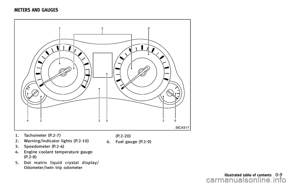
SIC4317
1. Tachometer (P.2-7)
2. Warning/Indicator lights (P.2-10)
3. Speedometer (P.2-6)
4. Engine coolant temperature gauge(P.2-8)
5. Dot matrix liquid crystal display/ Odometer/twin trip odometer (P.2-20)
6. Fuel gauge (P.2-9)
Illustrated table of contents0-9
METERS AND GAUGES
Page 71 of 522

1-52Safety—Seats, seat belts and supplemental restraint system
SSS1016
SUPPLEMENTAL AIR BAG WARNING
LABELS
Warning labels about the supplemental
front-impact air bag systems are placed in
the vehicle as shown in the illustration.
SRS air bag
The warning labels*1are located on the
surface of the sun visors.
SPA1097
SUPPLEMENTAL AIR BAG WARNING
LIGHT
The supplemental air bag warning light,
displaying
in the instrument panel,
monitors the circuits of the supplemental
front-impact air bag, front seat-mounted
side-impact supplemental air bag, roof-
mounted curtain side-impact supplemental
air bag, and seat belt pretensioner sys-
tems. The monitored circuits include the Air
bag Control Unit (ACU), satellite sensors,
crash zone sensor, occupant classification
system, front air bag modules, side air bag
modules, curtain air bag modules, preten- sioner, front passenger air bag status light
and all related wiring.
When the ignition switch is in the ON
position, the supplemental air bag warning
light illuminates for about 7 seconds and
then turns off. This means the SRS air bag
systems are operational.
If any of the following conditions occur, the
front air bag, side air bag, curtain air bag
and/or pretensioner systems need servi-
cing:
.
The supplemental air bag warning light
remains on approximately 7 seconds
after the ignition switch is pushed to
the ON position.
. The supplemental air bag warning light
flashes intermittently.
. The supplemental air bag warning light
does not come on at all.
Under these conditions, the front air bag,
side air bag, curtain air bag or pretensioner
systems may not operate properly. They
must be checked and repaired. Take your
vehicle to the nearest INFINITI retailer.
Page 74 of 522
2 Instruments and controls
Cockpit ................................................................ 2-3
Instrument panel ................................................. 2-5
Meters and gauges .............................................. 2-6Speedometer and odometer ............................ 2-6
Tachometer...................................................... 2-7
Engine coolant temperature gauge .................. 2-8
Fuel gauge ...................................................... 2-9
Warning/indicator lights and
audible reminders ............................................. 2-10 Checking bulbs.............................................. 2-10
Warning lights ............................................... 2-11
Indicator lights .............................................. 2-16
Audible reminders ......................................... 2-19
Dot matrix liquid crystal display ........................ 2-20 Indicators for operation ................................. 2-22
Indicators for maintenance ............................ 2-25
Trip computer ................................................ 2-26
Security systems ............................................... 2-29 Vehicle Security System ................................ 2-29
INFINITI Vehicle Immobilizer System .............. 2-30
Windshield wiper and washer switch ................. 2-31 Rain-sensing auto wiper system .................... 2-33
Rear window and outside mirror
defroster switch................................................. 2-34 Headlight and turn signal switch....................... 2-34
Xenon headlights......................................... 2-34
Headlight switch .......................................... 2-35
Turn signal switch........................................ 2-39
Fog light switch ........................................... 2-39
Hazard warning flasher switch .......................... 2-40
Heated steering wheel (if so equipped) ............. 2-40
Horn ................................................................. 2-41
Heated seats..................................................... 2-41
Climate controlled seats (if so equipped) .......... 2-43
Warning systems switch (if so equipped) .......... 2-44
Intelligent Brake Assist (IBA) OFF switch (if
so equipped)..................................................... 2-44
Vehicle Dynamic Control (VDC) OFF switch ......... 2-45
Clock................................................................. 2-46 Adjusting the time ....................................... 2-46
Power outlet ..................................................... 2-46
Cigarette lighter and ashtrays ........................... 2-47 Front............................................................ 2-47
Rear............................................................. 2-48
Storage ............................................................. 2-48 Cup holders ................................................. 2-48
Sunglasses holder ....................................... 2-49
Glove box .................................................... 2-50>
Page 78 of 522
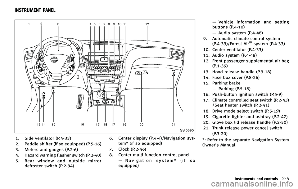
SSI0690
1. Side ventilator (P.4-33)
2. Paddle shifter (if so equipped) (P.5-16)
3. Meters and gauges (P.2-6)
4. Hazard warning flasher switch (P.2-40)
5. Rear window and outside mirrordefroster switch (P.2-34) 6. Center display (P.4-4)/Navigation sys-
tem* (if so equipped)
7. Clock (P.2-46)
8. Center multi-function control panel —Navigation system* (if so
equipped) —
Vehicle information and setting
buttons (P.4-10)
— Audio system (P.4-48)
9. Automatic climate control system (P.4-33)/Forest Air
®system (P.4-33)
10. Center ventilator (P.4-33)
11. Audio system (P.4-48)
12. Front passenger supplemental air bag (P.1-39)
13. Hood release handle (P.3-18)
14. Fuse box cover (P.8-26)
15. Parking brake —Parking (P.5-18)
16. Push-button ignition switch (P.5-9)
17. Climate controlled seat switch (P.2-43) /Seat heater switch (P.2-41)
18. Drive mode select switch (P.5-19)
19. Cigarette lighter and ashtray (P.2-47)
20. Glove box lid release handle (P.2-50)
21. Trunk release power cancel switch (P.3-20)
*: Refer to the separate Navigation System
Owner ’s Manual.
Instruments and controls2-5
INSTRUMENT PANEL
Page 79 of 522

2-6Instruments and controls
SIC4317
1. Tachometer (P.2-7)
2. Warning/Indicator lights (P.2-10)
3. Speedometer (P.2-6)
4. Engine coolant temperature gauge(P.2-8)
5. Dot matrix liquid crystal display/ Odometer/twin trip odometer (P.2-20) 6. Fuel gauge (P.2-9)
*: The needle indicators in the speed-
ometer, tachometer, engine coolant tem-
perature gauge and fuel gauge may move
slightly after the ignition switch is pushed
to the LOCK position. This is not a
malfunction.
SIC4318
Speedometer
SPEEDOMETER AND ODOMETER
Speedometer
The speedometer indicates vehicle speed
in miles per hour (MPH) and kilometers per
hour (km/h).
METERS AND GAUGES
Page 80 of 522

SIC4319
Odometer/twin trip odometer
Odometer/twin trip odometer
The odometer*1and twin trip odometer
*2are displayed on the dot matrix crystal
display when the ignition switch is in the
ON position.
The odometer records the total distance
the vehicle has been driven.
The twin trip odometer records the dis-
tance of individual trips.
Changing the display:
Pushing the TRIP RESET switch
*3on the
right of the combination meter panel
changes the display as follows: TRIP A
?TRIP B ?TRIP A
Resetting the trip odometer:
Pushing the TRIP RESET switch
*3for more
than 1 second resets the trip odometer to
zero.
Average fuel economy and distance to
empty information is also available. (See
“ Dot matrix liquid crystal display ”later in
this section and “How to use STATUS
button ”in the “4. Monitor, climate, audio,
phone and voice recognition systems ”
section.)
SIC4320
TACHOMETER
The tachometer indicates engine speed in
revolutions per minute (RPM). Do not rev
the engine into the red zone
*1.
The scale length and the red zone vary with
the engine model.
CAUTION
When engine speed approaches the red
zone, shift to a higher gear or reduce engine
speed. Operating the engine in the red zone
may cause serious engine damage.
Instruments and controls2-7
Page 82 of 522

SIC4322
FUEL GAUGE
The gauge indicates theapproximatefuel
level in the tank.
The gauge may move slightly during
braking, turning, acceleration, or going up
or down hills.
The gauge needle returns to “0 ” (Empty)
after the ignition switch is pushed to the
OFF position.
Refill the fuel tank before the gauge
registers “0”(Empty).
The low fuel warning
appears on the
dot matrix liquid crystal display when the fuel level is getting low. Refuel as soon as
it is convenient, preferably before the
gauge reaches
“0 ”. There will be a small
reserve of fuel in the tank when the fuel
gauge needle reaches “0 ”.
CAUTION
. If the vehicle runs out of fuel, the
malfunction indicator light (MIL) may
come on. Refuel as soon as possible.
After a few driving trips, the
light
should turn off. If the light remains on
after a few driving trips, have the vehicle
inspected by an INFINITI retailer.
. For additional information, see “Mal-
function Indicator Light (MIL) ”later in
this section.
Instruments and controls2-9
Page 83 of 522
2-10Instruments and controls
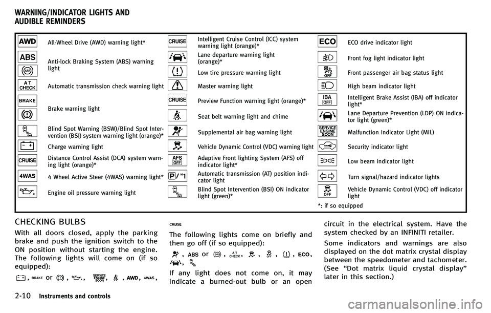
All-Wheel Drive (AWD) warning light*Intelligent Cruise Control (ICC) system
warning light (orange)*ECO drive indicator light
Anti-lock Braking System (ABS) warning
lightLane departure warning light
(orange)*Front fog light indicator light
Low tire pressure warning lightFront passenger air bag status light
Automatic transmission check warning lightMaster warning lightHigh beam indicator light
Brake warning lightPreview Function warning light (orange)*Intelligent Brake Assist (IBA) off indicator
light*
Seat belt warning light and chimeLane Departure Prevention (LDP) ON indica-
tor light (green)*
Blind Spot Warning (BSW)/Blind Spot Inter-
vention (BSI) system warning light (orange)*Supplemental air bag warning lightMalfunction Indicator Light (MIL)
Charge warning lightVehicle Dynamic Control (VDC) warning lightSecurity indicator light
Distance Control Assist (DCA) system warn-
ing light (orange)*Adaptive Front lighting System (AFS) off
indicator light*Low beam indicator light
4 Wheel Active Steer (4WAS) warning light*Automatic transmission (AT) position indi-
cator lightTurn signal/hazard indicator lights
Engine oil pressure warning lightBlind Spot Intervention (BSI) ON indicator
light (green)*Vehicle Dynamic Control (VDC) off indicator
light
*: if so equipped
CHECKING BULBS
With all doors closed, apply the parking
brake and push the ignition switch to the
ON position without starting the engine.
The following lights will come on (if so
equipped):
,or,,,,,,
The following lights come on briefly and
then go off (if so equipped):
,or,,,,,,
,
If any light does not come on, it may
indicate a burned-out bulb or an open circuit in the electrical system. Have the
system checked by an INFINITI retailer.
Some indicators and warnings are also
displayed on the dot matrix crystal display
between the speedometer and tachometer.
(See
“Dot matrix liquid crystal display ”
later in this section.)
WARNING/INDICATOR LIGHTS AND
AUDIBLE REMINDERS
Page 87 of 522
2-14Instruments and controls
systems are not functioning properly. Have
the systems checked by an INFINITI retailer.
See“Lane Departure Warning (LDW) sys-
tem/Lane Departure Prevention (LDP) sys-
tem ”in the “5. Starting and driving ”
section.
Low tire pressure warning
light
Your vehicle is equipped with a Tire
Pressure Monitoring System (TPMS) that
monitors the tire pressure of all tires
except the spare.
The low tire pressure warning light warns
of low tire pressure or indicates that the
TPMS is not functioning properly.
After the ignition switch is pushed ON, this
light illuminates for about 1 second and
turns off.
Low tire pressure warning:
If the vehicle is being driven with low tire
pressure, the warning light will illuminate.
A CHECK TIRE PRESSURE warning also
appears in the dot matrix liquid crystal
display.
If you select tire pressure information in
the display, the LOW PRESSURE warning
message will be displayed. The tire pres- sure for each tire will also be displayed.
When the low tire pressure warning light
illuminates, you should stop and adjust
the tire pressure to the recommended
COLD tire pressure shown on the Tire and
Loading Information label. The low tire
pressure warning light does not automati-
cally turn off when the tire pressure is
adjusted. After the tire is inflated to the
recommended pressure, the vehicle must
be driven at speeds above 16 MPH (25
km/h) to activate the TPMS and turn off the
low tire pressure warning light. Use a tire
pressure gauge to check the tire pressure.
The CHECK TIRE PRESSURE warning is
active as long as the low tire pressure
warning light remains illuminated.
For additional information, see
“Dot matrix
liquid crystal display ”later in this section,
“ Tire Pressure Monitoring System (TPMS) ”
in the “5. Starting and driving ”section and
“ Tire Pressure Monitoring System (TPMS) ”
in the “6. In case of emergency” section.
TPMS malfunction:
If the TPMS is not functioning properly, the
low tire pressure warning light will flash for
approximately 1 minute when the ignition
switch is pushed ON. The light will remain on after the 1 minute. Have the system
checked by an INFINITI retailer. The CHECK
TIRE PRESSURE warning does not appear if
the low tire pressure warning light illumi-
nates to indicate a TPMS malfunction.
For additional information, see
“Tire Pres-
sure Monitoring System (TPMS) ”in the “5.
Starting and driving ”section.WARNING
. If the light does not illuminate with the
ignition switch pushed ON, have the
vehicle checked by an INFINITI retailer as
soon as possible.
. If the light illuminates while driving,
avoid sudden steering maneuvers or
abrupt braking, reduce vehicle speed,
pull off the road to a safe location and
stop the vehicle as soon as possible.
Driving with under-inflated tires may
permanently damage the tires and in-
crease the likelihood of tire failure.
Serious vehicle damage could occur
and may lead to an accident and could
result in serious personal injury. Check
the tire pressure for all four tires. Adjust
the tire pressure to the recommended
COLD tire pressure shown on the Tire