brake INFINITI QX4 2001 Factory Service Manual
[x] Cancel search | Manufacturer: INFINITI, Model Year: 2001, Model line: QX4, Model: INFINITI QX4 2001Pages: 2395, PDF Size: 43.2 MB
Page 2016 of 2395
SMA211A
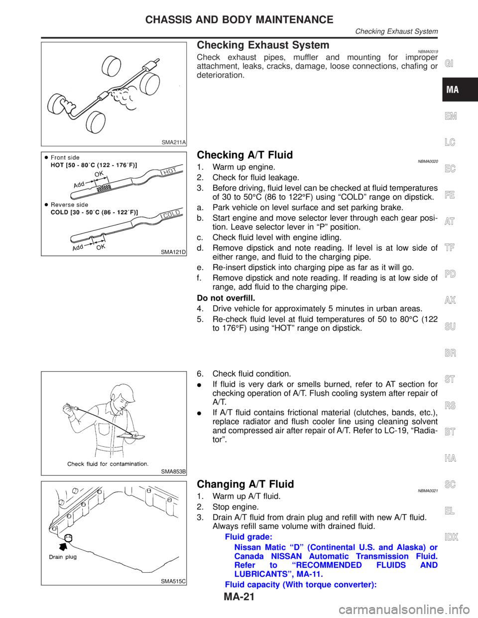
Checking Exhaust SystemNBMA0019Check exhaust pipes, muffler and mounting for improper
attachment, leaks, cracks, damage, loose connections, chafing or
deterioration.
SMA121D
Checking A/T FluidNBMA00201. Warm up engine.
2. Check for fluid leakage.
3. Before driving, fluid level can be checked at fluid temperatures
of 30 to 50ÉC (86 to 122ÉF) using ªCOLDº range on dipstick.
a. Park vehicle on level surface and set parking brake.
b. Start engine and move selector lever through each gear posi-
tion. Leave selector lever in ªPº position.
c. Check fluid level with engine idling.
d. Remove dipstick and note reading. If level is at low side of
either range, and fluid to the charging pipe.
e. Re-insert dipstick into charging pipe as far as it will go.
f. Remove dipstick and note reading. If reading is at low side of
range, add fluid to the charging pipe.
Do not overfill.
4. Drive vehicle for approximately 5 minutes in urban areas.
5. Re-check fluid level at fluid temperatures of 50 to 80ÉC (122
to 176ÉF) using ªHOTº range on dipstick.
SMA853B
6. Check fluid condition.
IIf fluid is very dark or smells burned, refer to AT section for
checking operation of A/T. Flush cooling system after repair of
A/T.
IIf A/T fluid contains frictional material (clutches, bands, etc.),
replace radiator and flush cooler line using cleaning solvent
and compressed air after repair of A/T. Refer to LC-19, ªRadia-
torº.
SMA515C
Changing A/T FluidNBMA00211. Warm up A/T fluid.
2. Stop engine.
3. Drain A/T fluid from drain plug and refill with new A/T fluid.
Always refill same volume with drained fluid.
Fluid grade:
Nissan Matic ªDº (Continental U.S. and Alaska) or
Canada NISSAN Automatic Transmission Fluid.
Refer to ªRECOMMENDED FLUIDS AND
LUBRICANTSº, MA-11.
Fluid capacity (With torque converter):
GI
EM
LC
EC
FE
AT
TF
PD
AX
SU
BR
ST
RS
BT
HA
SC
EL
IDX
CHASSIS AND BODY MAINTENANCE
Checking Exhaust System
MA-21
Page 2020 of 2395

SBR451D
Checking Brake Fluid Level and LeaksNBMA0030If fluid level is extremely low, check brake system for leaks.
SBR389C
Checking Brake Lines and CablesNBMA0031Check brake fluid lines and parking brake cables for improper
attachment, leaks, chafing, abrasions and deterioration.
SMA260A
Checking Disc BrakeNBMA0032ROTORNBMA0032S01Check condition and thickness.
Standard thickness:
28 mm (1.10 in)
Minimum thickness:
26 mm (1.02 in)
SMA922A
CALIPERNBMA0032S02Check for leakage.
SMA847B
PADNBMA0032S03Check wear or damage.
Standard thickness:
11 mm (0.43 in)
Minimum thickness:
2 mm (0.08 in)
GI
EM
LC
EC
FE
AT
TF
PD
AX
SU
BR
ST
RS
BT
HA
SC
EL
IDX
CHASSIS AND BODY MAINTENANCE
Checking Brake Fluid Level and Leaks
MA-25
Page 2021 of 2395
SMA848B
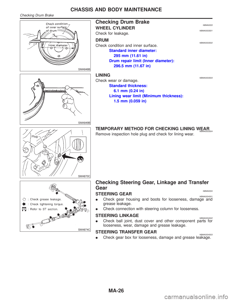
Checking Drum BrakeNBMA0033WHEEL CYLINDERNBMA0033S01Check for leakage.
DRUMNBMA0033S02Check condition and inner surface.
Standard inner diameter:
295 mm (11.61 in)
Drum repair limit (Inner diameter):
296.5 mm (11.67 in)
SMA849B
LININGNBMA0033S03Check wear or damage.
Standard thickness:
6.1 mm (0.24 in)
Lining wear limit (Minimum thickness):
1.5 mm (0.059 in)
SMA870C
TEMPORARY METHOD FOR CHECKING LINING WEARNBMA0033S04Remove inspection hole plug and check for lining wear.
SMA874C
Checking Steering Gear, Linkage and Transfer
Gear
NBMA0034STEERING GEARNBMA0034S01ICheck gear housing and boots for looseness, damage and
grease leakage.
ICheck connection with steering column for looseness.
STEERING LINKAGENBMA0034S02ICheck ball joint, dust cover and other component parts for
looseness, wear, damage and grease leakage.
STEERING TRANSFER GEARNBMA0034S03ICheck gear box for looseness, damage and grease leakage.
CHASSIS AND BODY MAINTENANCE
Checking Drum Brake
MA-26
Page 2028 of 2395

Noise, Vibration and Harshness (NVH)
Troubleshooting
=NBPD0049NVH TROUBLESHOOTING CHARTNBPD0049S01Use the chart below to help you find the cause of the symptom. If necessary, repair or replace these parts.
Reference pageÐ
Ð
Ð
Ð
PD-6
PD-6
PD-23, 47
PD-29, 56
PD-23, 47
PD-18, 43
Ð
Ð
Ð
Ð
AX-3
AX-3
SU-3
SU-3
SU-3
BR-6
ST-6
Possible cause and
SUSPECTED PARTS
Uneven rotation torque
Excessive center bearing axial end play
Center bearing mounting (insulator) cracks, damage or deterioration
Excessive joint angle
Rotation imbalance
Excessive runout
Rough gear tooth
Improper gear contact
Tooth surfaces worn
Incorrect backlash
Companion flange excessive runout
Improper gear oil
PROPELLER SHAFT
DIFFERENTIAL
DRIVE SHAFT
AXLE
SUSPENSION
TIRES
ROAD WHEEL
BRAKES
STEERING
SymptomPROPEL-
LER
SHAFTNoise´´´´´´ ´´´´´´´´
Shake´ ´´´´´´´
Vibration´´´´´´ ´´´´ ´
DIFFER-
ENTIALNoise´´´´´´´ ´´´´´´´
´: Applicable
GI
MA
EM
LC
EC
FE
AT
TF
AX
SU
BR
ST
RS
BT
HA
SC
EL
IDX
PROPELLER SHAFT
Noise, Vibration and Harshness (NVH) Troubleshooting
PD-3
Page 2097 of 2395
SEAT BELT RETRACTOR ON-VEHICLE CHECKNBRS0029S03Emergency Locking Retractors (ELR) and Automatic Locking Retractors (ALR)NBRS0029S0301NOTE:
All seat belt retractors are of the Emergency Locking Retractors (ELR) type. In an emergency (sudden stop)
the retractor will lock and prevent the belt from extending any further. All 3-point type seat belt retractors except
the driver's seat belt also have an Automatic Locking Retractors (ALR) mode. The ALR mode (also called child
restraint mode) is used when installing child seats. The ALR mode is activated when the seat belt is fully
extended. When the belt is then retracted partially, the ALR mode automatically locks the seat belt in a spe-
cific position so the belt cannot be extended any further. To cancel the ALR mode, allow the seat belt to fully
wind back into the retractor.
Check the seat belt retractors using the following test(s) to determine if a retractor assembly is operating
properly.
ELR Function Stationary CheckNBRS0029S0302Grasp the shoulder belt and pull forward quickly. The retractor should lock and prevent the belt from extend-
ing further.
ALR Function Stationary CheckNBRS0029S03041. Pull out entire length of seat belt from retractor until a click is heard.
2. Retract the belt partially. A clicking noise should be heard as the belt retracts indicating that the retractor
is in the Automatic Locking Retractors (ALR) mode.
3. Grasp the seat belt and try to pull out the retractor. The belt must lock and not extend any further. If NG,
replace the retractor assembly.
4. Allow the entire length of the belt to retract to cancel the automatic locking mode.
ELR Function Moving CheckNBRS0029S0303WARNING:
Perform the following test in a safe, open area clear of other vehicles and obstructions (for example,
a large, empty parking lot). Road surface must be paved and dry. DO NOT perform the following test
on wet or gravel roads or on public streets and highways. This could result in an accident and seri-
ous personal injury. The driver and passenger must be prepared to brace themselves in the event the
retractor does not lock.
1. Fasten driver's seat belt. Buckle a passenger into the seat for the belt that is to be tested.
2. Proceed to the designated safe area.
3. Drive the vehicle at approximately 16 km/h (10 MPH). Notify any passengers of a pending sudden stop
and the driver and passenger must be prepared to brace themselves in the event the retractor does not
lock, apply brakes firmly and make a very hard stop.
During stop, seat belts should lock and not be extended. If the seat belt retractor assembly does not lock,
perform the retractor off-vehicle check.
SEAT BELT RETRACTOR OFF-VEHICLE CHECKNBRS0029S041. Remove the seat belt retractor assembly.
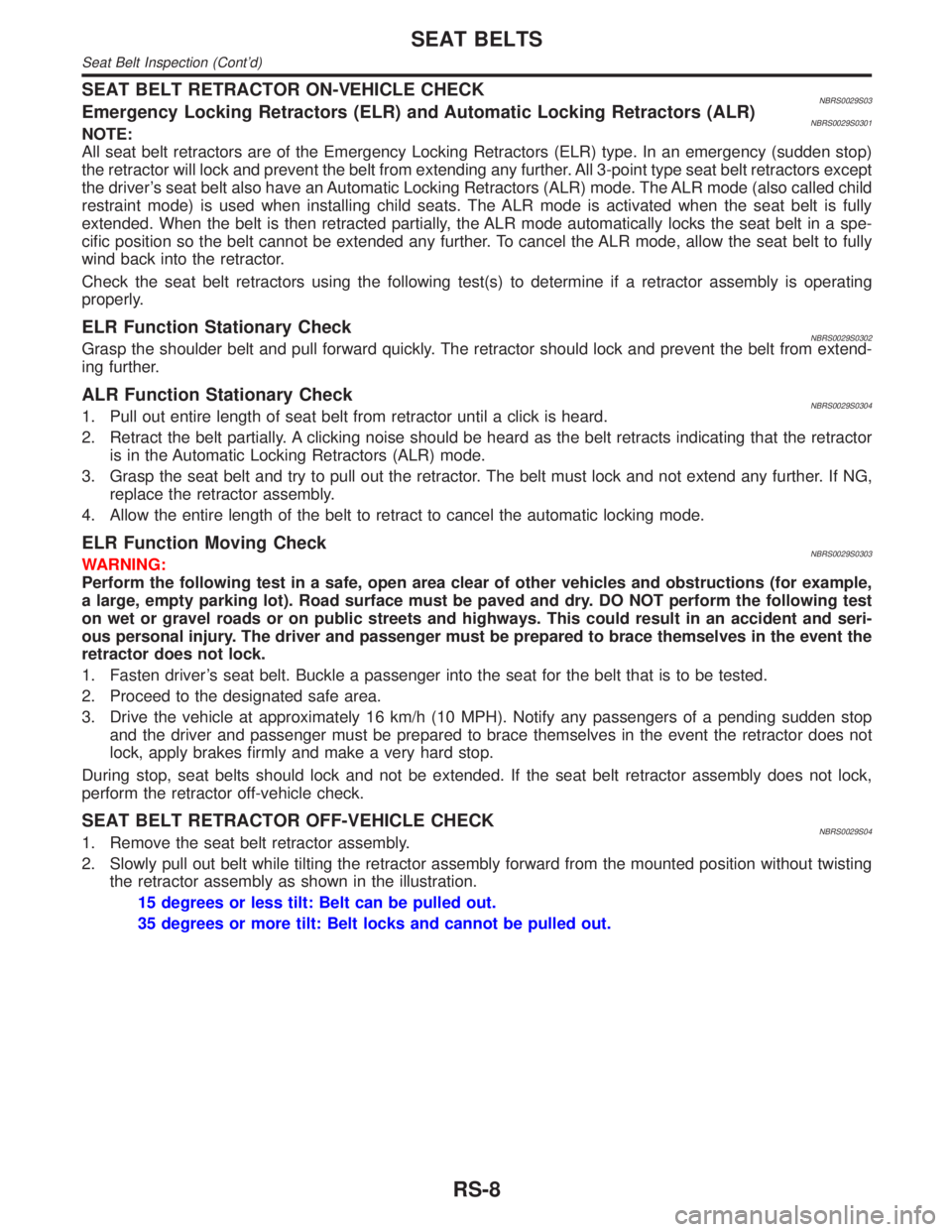
2. Slowly pull out belt while tilting the retractor assembly forward from the mounted position without twisting
the retractor assembly as shown in the illustration.
15 degrees or less tilt: Belt can be pulled out.
35 degrees or more tilt: Belt locks and cannot be pulled out.
SEAT BELTS
Seat Belt Inspection (Cont'd)
RS-8
Page 2187 of 2395

NBST0043
NVH Troubleshooting ChartNBST0043S01Use the chart below to help you find the cause of the symptom. If necessary, repair or replace these parts.
Reference pageST-8
ST-9
ST-21
ST-21
ST-21
ST-8
ST-7
ST-9
MA-13
Ð
ST-13
ST-8
ST-13
ST-13
ST-17
PD-3
PD-3
AX-3
AX-3
SU-3
SU-3
SU-3
BR-6
Possible cause and
SUSPECTED PARTS
Fluid level
Air in hydraulic system
Tie-rod ball joint swinging force
Tie-rod ball joint rotating torque
Tie-rod ball joint end play
Steering gear fluid leakage
Steering wheel play
Steering gear rack sliding force
Drive belt looseness
Improper steering wheel
Improper installation or looseness or tilt lock lever
Mounting rubber deterioration
Steering column deformation or damage
Improper installation or looseness of steering column
Steering linkage looseness
PROPELLER SHAFT
DIFFERENTIAL
DRIVE SHAFT
AXLE
SUSPENSION
TIRES
ROAD WHEEL
BRAKES
Symp-
tomSTEERINGNoise´´´´´´´´´ ´´´´´´´´
Shake´´´ ´ ´´´´´´
Vibration´´´´´ ´ ´´´´
Shimmy´´´ ´ ´´´´´
Judder´ ´ ´´´´´
´: Applicable
NOISE, VIBRATION AND HARSHNESS (NVH) TROUBLESHOOTING
NVH Troubleshooting Chart
ST-6
Page 2190 of 2395
CAUTION:
Do not hold the steering wheel in a locked position for more
than 15 seconds.
4. If fluid leakage at connectors is noticed, loosen flare nut and
then retighten.
Do not overtighten connector as this can damage O-ring,
washer and connector.
5. Check rack boots for accumulation of power steering fluid.
Bleeding Hydraulic SystemNBST00131. Raise front end of vehicle until wheels are clear of the ground.
2. Add fluid into oil tank to specified level. Then, quickly turn
steering wheel fully to right and left and lightly touch steering
stoppers.
Repeat steering wheel operation until fluid level no longer
decreases.
3. Start engine.
Repeat step 2 above.
IIncomplete air bleeding will cause the following to occur. When
this happens, bleed air again.
a) Air bubbles in reservoir tank
b) Clicking noise in oil pump
c) Excessive buzzing in oil pump
Fluid noise may occur in the valve or oil pump. This is common
when the vehicle is stationary or while turning steering wheel
slowly. This does not affect performance or durability of the system.
SST491B
SST090B
Checking Steering Wheel Turning ForceNBST00141. Park vehicle on a level, dry surface and set parking brake.
2. Start engine.
3. Bring power steering fluid up to adequate operating tempera-
ture. [Make sure temperature of fluid is approximately 60 to
80ÉC (140 to 176ÉF).]
Tires need to be inflated to normal pressure.
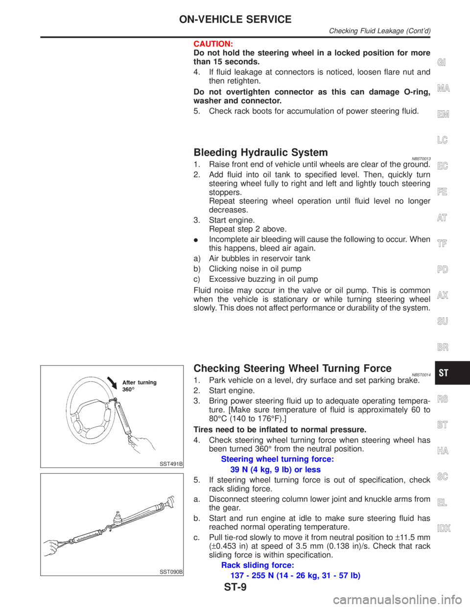
4. Check steering wheel turning force when steering wheel has
been turned 360É from the neutral position.
Steering wheel turning force:
39 N (4 kg, 9 lb) or less
5. If steering wheel turning force is out of specification, check
rack sliding force.
a. Disconnect steering column lower joint and knuckle arms from
the gear.
b. Start and run engine at idle to make sure steering fluid has
reached normal operating temperature.
c. Pull tie-rod slowly to move it from neutral position to±11.5 mm
(±0.453 in) at speed of 3.5 mm (0.138 in)/s. Check that rack
sliding force is within specification.
Rack sliding force:
137 - 255 N (14 - 26 kg, 31 - 57 lb)
GI
MA
EM
LC
EC
FE
AT
TF
PD
AX
SU
BR
RS
BT
HA
SC
EL
IDX
ON-VEHICLE SERVICE
Checking Fluid Leakage (Cont'd)
ST-9
Page 2217 of 2395
SBR686C
Precautions
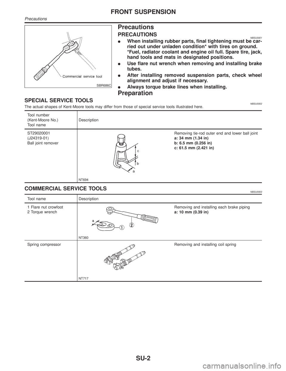
PRECAUTIONSNBSU0001IWhen installing rubber parts, final tightening must be car-
ried out under unladen condition* with tires on ground.
*Fuel, radiator coolant and engine oil full. Spare tire, jack,
hand tools and mats in designated positions.
IUse flare nut wrench when removing and installing brake
tubes.
IAfter installing removed suspension parts, check wheel
alignment and adjust if necessary.
IAlways torque brake lines when installing.
Preparation
SPECIAL SERVICE TOOLSNBSU0002The actual shapes of Kent-Moore tools may differ from those of special service tools illustrated here.
Tool number
(Kent-Moore No.)
Tool nameDescription
ST29020001
(J24319-01)
Ball joint remover
NT694
Removing tie-rod outer end and lower ball joint
a: 34 mm (1.34 in)
b: 6.5 mm (0.256 in)
c: 61.5 mm (2.421 in)
COMMERCIAL SERVICE TOOLSNBSU0003
Tool name Description
1 Flare nut crowfoot
2 Torque wrench
NT360
Removing and installing each brake piping
a: 10 mm (0.39 in)
Spring compressor
NT717
Removing and installing coil spring
FRONT SUSPENSION
Precautions
SU-2
Page 2218 of 2395
Noise, Vibration and Harshness (NVH)
Troubleshooting
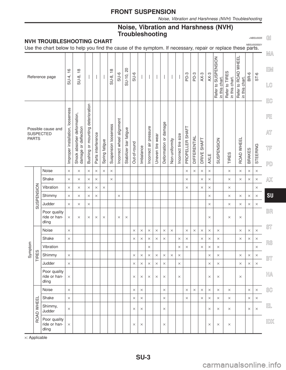
=NBSU0035NVH TROUBLESHOOTING CHARTNBSU0035S01Use the chart below to help you find the cause of the symptom. If necessary, repair or replace these parts.
Reference page
SU-4, 16
SU-8, 18
Ð
Ð
Ð
SU-8, 18
SU-6
SU-10, 20
SU-6
Ð
Ð
Ð
Ð
Ð
Ð
PD-3
PD-3
AX-3
AX-3
Refer to SUSPENSION
in this chart.
Refer to TIRES
in this chart.
Refer to ROAD WHEEL
in this chart.
BR-6
ST-6
Possible cause and
SUSPECTED
PA R T S
Improper installation, looseness
Shock absorber deformation,
damage or deflection
Bushing or mounting deterioration
Parts interference
Spring fatigue
Suspension looseness
Incorrect wheel alignment
Stabilizer bar fatigue
Out-of-round
Imbalance
Incorrect air pressure
Uneven tire wear
Deformation or damage
Non-uniformity
Incorrect tire size
PROPELLER SHAFT
DIFFERENTIAL
DRIVE SHAFT
AXLE
SUSPENSION
TIRES
ROAD WHEEL
BRAKES
STEERING Symptom
SUSPENSION
Noise´ ´ ´´´´ ´´´´ ´ ´ ´´
Shake´´´´´ ´´´ ´´´´
Vibration´ ´ ´´´ ´ ´´ ´ ´
Shimmy´´´´ ´ ´ ´ ´´´
Judder´´´ ´ ´ ´´´
Poor quality
ride or han-
dling´ ´ ´´´ ´´ ´ ´ ´
TIRES
Noise´ ´´´´´´ ´´´´ ´ ´ ´´
Shake´ ´´´´´ ´´ ´´ ´ ´ ´´
Vibration´´´´´´ ´
Shimmy´ ´´´´´´´ ´ ´ ´ ´´
Judder´ ´´´´´ ´ ´ ´ ´ ´´
Poor quality
ride or han-
dling´ ´´´´´ ´ ´ ´ ´
ROAD WHEEL
Noise´ ´´ ´ ´´´´ ´ ´ ´´
Shake´ ´´ ´ ´ ´´ ´ ´ ´´
Shimmy,
Judder´´´´´´´´´
Poor quality
ride or han-
dling´´´´´´´
´: Applicable
GI
MA
EM
LC
EC
FE
AT
TF
PD
AX
BR
ST
RS
BT
HA
SC
EL
IDX
FRONT SUSPENSION
Noise, Vibration and Harshness (NVH) Troubleshooting
SU-3
Page 2220 of 2395
SMA525A
On-vehicle Service
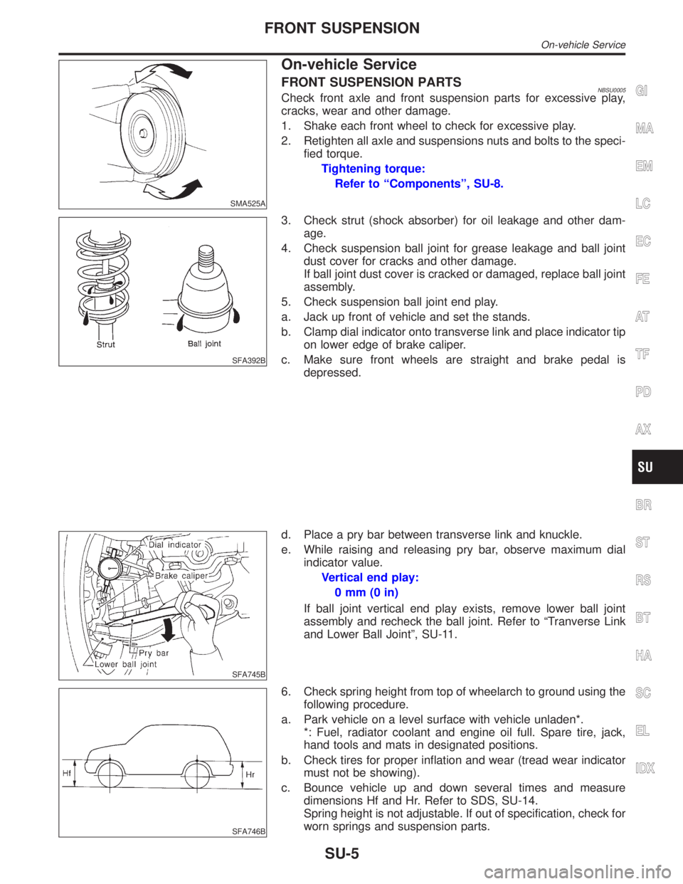
FRONT SUSPENSION PARTSNBSU0005Check front axle and front suspension parts for excessive play,
cracks, wear and other damage.
1. Shake each front wheel to check for excessive play.
2. Retighten all axle and suspensions nuts and bolts to the speci-
fied torque.
Tightening torque:
Refer to ªComponentsº, SU-8.
SFA392B
3. Check strut (shock absorber) for oil leakage and other dam-
age.
4. Check suspension ball joint for grease leakage and ball joint
dust cover for cracks and other damage.
If ball joint dust cover is cracked or damaged, replace ball joint
assembly.
5. Check suspension ball joint end play.
a. Jack up front of vehicle and set the stands.
b. Clamp dial indicator onto transverse link and place indicator tip
on lower edge of brake caliper.
c. Make sure front wheels are straight and brake pedal is
depressed.
SFA745B
d. Place a pry bar between transverse link and knuckle.
e. While raising and releasing pry bar, observe maximum dial
indicator value.
Vertical end play:
0mm(0in)
If ball joint vertical end play exists, remove lower ball joint
assembly and recheck the ball joint. Refer to ªTranverse Link
and Lower Ball Jointº, SU-11.
SFA746B
6. Check spring height from top of wheelarch to ground using the
following procedure.
a. Park vehicle on a level surface with vehicle unladen*.
*: Fuel, radiator coolant and engine oil full. Spare tire, jack,
hand tools and mats in designated positions.
b. Check tires for proper inflation and wear (tread wear indicator
must not be showing).
c. Bounce vehicle up and down several times and measure
dimensions Hf and Hr. Refer to SDS, SU-14.
Spring height is not adjustable. If out of specification, check for
worn springs and suspension parts.
GI
MA
EM
LC
EC
FE
AT
TF
PD
AX
BR
ST
RS
BT
HA
SC
EL
IDX
FRONT SUSPENSION
On-vehicle Service
SU-5