oil INFINITI QX4 2001 Factory Service Manual
[x] Cancel search | Manufacturer: INFINITI, Model Year: 2001, Model line: QX4, Model: INFINITI QX4 2001Pages: 2395, PDF Size: 43.2 MB
Page 2228 of 2395
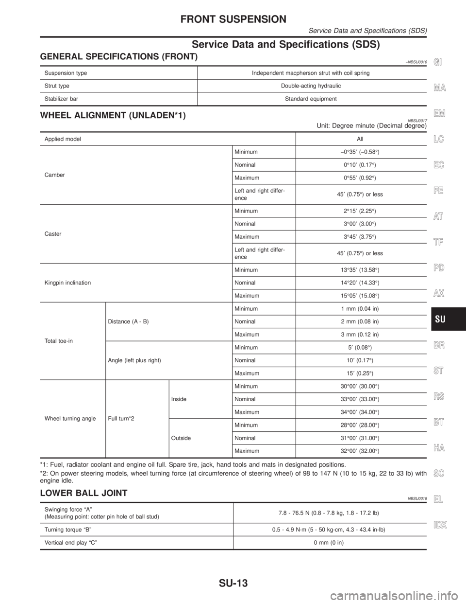
Service Data and Specifications (SDS)
GENERAL SPECIFICATIONS (FRONT)=NBSU0016
Suspension type Independent macpherson strut with coil spring
Strut typeDouble-acting hydraulic
Stabilizer barStandard equipment
WHEEL ALIGNMENT (UNLADEN*1)NBSU0017Unit: Degree minute (Decimal degree)
Applied modelAll
CamberMinimum þ0É35¢(þ0.58É)
Nominal 0É10¢(0.17É)
Maximum 0É55¢(0.92É)
Left and right differ-
ence45¢(0.75É) or less
CasterMinimum 2É15¢(2.25É)
Nominal 3É00¢(3.00É)
Maximum 3É45¢(3.75É)
Left and right differ-
ence45¢(0.75É) or less
Kingpin inclinationMinimum 13É35¢(13.58É)
Nominal 14É20¢(14.33É)
Maximum 15É05¢(15.08É)
Total toe-inDistance (A - B)Minimum 1 mm (0.04 in)
Nominal 2 mm (0.08 in)
Maximum 3 mm (0.12 in)
Angle (left plus right)Minimum 5¢(0.08É)
Nominal 10¢(0.17É)
Maximum 15¢(0.25É)
Wheel turning angle Full turn*2InsideMinimum 30É00¢(30.00É)
Nominal 33É00¢(33.00É)
Maximum 34É00¢(34.00É)
OutsideMinimum 28É00¢(28.00É)
Nominal 31É00¢(31.00É)
Maximum 32É00¢(32.00É)
*1: Fuel, radiator coolant and engine oil full. Spare tire, jack, hand tools and mats in designated positions.
*2: On power steering models, wheel turning force (at circumference of steering wheel) of 98 to 147 N (10 to 15 kg, 22 to 33 lb) with
engine idle.
LOWER BALL JOINTNBSU0018
Swinging force ªAº
(Measuring point: cotter pin hole of ball stud)7.8 - 76.5 N (0.8 - 7.8 kg, 1.8 - 17.2 lb)
Turning torque ªBº 0.5 - 4.9 N´m (5 - 50 kg-cm, 4.3 - 43.4 in-lb)
Vertical end play ªCº0mm(0in)
GI
MA
EM
LC
EC
FE
AT
TF
PD
AX
BR
ST
RS
BT
HA
SC
EL
IDX
FRONT SUSPENSION
Service Data and Specifications (SDS)
SU-13
Page 2229 of 2395

WHEELARCH HEIGHT (UNLADEN*)NBSU0019Unit: mm (in)
SFA746B
Applied model 245/70 R16 tire 245/65 R17 tire
Front (Hf)794 (31.26)
Rear (Hr)810 (31.89)
*: Fuel, radiator coolant and engine oil full. Spare tire, jack, hand tools and mats in designated positions.
WHEEL RUNOUT AVERAGE*NBSU0020Unit: mm (in)
Radial runout limit0.3 (0.012)
Lateral runout limit0.3 (0.012)
*: Wheel runout average = (Outside runout value + Inside runout value) x 0.5
FRONT SUSPENSION
Service Data and Specifications (SDS) (Cont'd)
SU-14
Page 2230 of 2395

SBR686C
Precautions
PRECAUTIONSNBSU0021IWhen installing rubber parts, final tightening must be car-
ried out under unladen condition* with tires on ground.
*Fuel, radiator coolant and engine oil full. Spare tire, jack,
hand tools and mats in designated positions.
IUse flare nut wrench when removing and installing brake
tubes.
IAfter installing removed suspension parts, check wheel
alignment and adjust if necessary.
IAlways torque brake lines when installing.
Preparation
COMMERCIAL SERVICE TOOLSNBSU0023
Tool name Description
1 Flare nut crowfoot
2 Torque wrench
NT360
Removing and installing each brake piping
a: 10 mm (0.39 in)
Noise, Vibration and Harshness (NVH)
Troubleshooting
NBSU0036Refer to ªNoise, Vibration and Harshness (NVH) Troubleshootingº,
ªFRONT SUSPENSIONº, SU-3.
GI
MA
EM
LC
EC
FE
AT
TF
PD
AX
BR
ST
RS
BT
HA
SC
EL
IDX
REAR SUSPENSION
Precautions
SU-15
Page 2231 of 2395

ComponentsNBSU0024
SRA880A
SMA525A
On-vehicle Service
REAR SUSPENSION PARTSNBSU0025Check rear axle and rear suspension parts for excessive play, wear
and damage.
1. Shake each rear wheel to check for excessive play.
2. Retighten all nuts and bolts to the specified torque.
Tightening torque: Refer to ªCoil Spring and Shock
Absorberº, SU-18.
SRA754A
3. Check shock absorber for oil leakage and other damage.
4. Check shock absorber bushing for excessive wear and other
damage.
5. Check wheelarch height. Refer to ªOn-vehicle Serviceº,
ªFRONT SUSPENSIONº, SU-5.
REAR SUSPENSION
Components
SU-16
Page 2233 of 2395
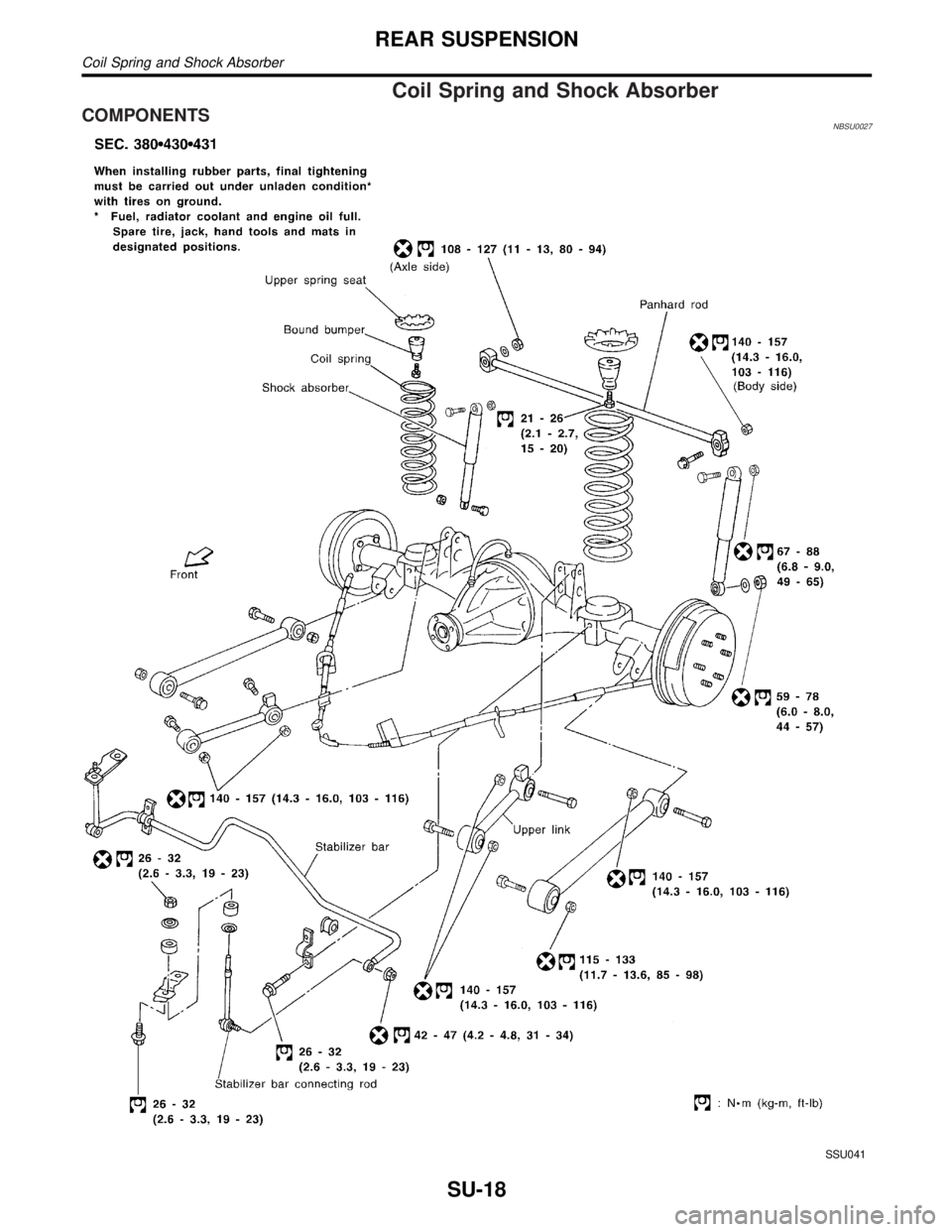
Coil Spring and Shock Absorber
COMPONENTSNBSU0027
SSU041
REAR SUSPENSION
Coil Spring and Shock Absorber
SU-18
Page 2234 of 2395

SRA645A
REMOVAL AND INSTALLATIONNBSU0028Refer to ªRemoval and Installationº, ªREAR SUSPENSIONº,
SU-17.
When installing coil spring, pay attention to its direction.
Be sure spring rubber seat is not twisted and has not slipped
off when installing coil spring.
INSPECTIONNBSU0029ICheck coil spring for yield, deformation and cracks.
ICheck shock absorber for oil leakage, cracks and deformation.
ICheck all rubber parts for wear, cracks and deformation.
Replace if necessary.
Upper Link, Lower Link and Panhard Rod
INSPECTIONNBSU0030Check for cracks, distortion and other damage. Replace if
necessary.
SRA898
BUSHING REPLACEMENTNBSU0031Check for cracks and other damage. Replace with suitable tool if
necessary.
IRemove bushing with suitable tool.
SRA900
When installing bushing, apply a coat of 1% soapy water to
outer wall of bushing.
Always install new bushing.
Do not tap end face of bushing directly with a hammer.
GI
MA
EM
LC
EC
FE
AT
TF
PD
AX
BR
ST
RS
BT
HA
SC
EL
IDX
REAR SUSPENSION
Coil Spring and Shock Absorber (Cont'd)
SU-19
Page 2235 of 2395
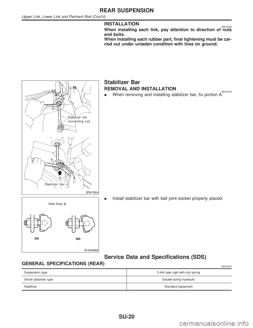
INSTALLATIONNBSU0032When installing each link, pay attention to direction of nuts
and bolts.
When installing each rubber part, final tightening must be car-
ried out under unladen condition with tires on ground.
SRA766A
Stabilizer Bar
REMOVAL AND INSTALLATIONNBSU0033IWhen removing and installing stabilizer bar, fix portion A.
SFA449BA
IInstall stabilizer bar with ball joint socket properly placed.
Service Data and Specifications (SDS)
GENERAL SPECIFICATIONS (REAR)NBSU0034
Suspension type5-link type rigid with coil spring
Shock absorber typeDouble-acting hydraulic
StabilizerStandard equipment
REAR SUSPENSION
Upper Link, Lower Link and Panhard Rod (Cont'd)
SU-20
Page 2237 of 2395

LINE PRESSURE SWITCH...........................................83
Diagnostic Procedure ................................................83
ABS OPERATION SIGNAL...........................................86
Diagnostic Procedure ................................................86
DATA ERASE/DISPLAY...............................................88
Diagnostic Procedure ................................................88
SHIFT ACTUATOR........................................................89
Diagnostic Procedure ................................................89
SHIFT ACTUATOR POSITION SWITCH......................92
Diagnostic Procedure ................................................92
SHIFT ACTUATOR CIRCUIT........................................94
Diagnostic Procedure ................................................94
TROUBLE DIAGNOSES FOR SYMPTOMS.................98
Symptom 1. 4WD Shift Indicator Lamp Does Not
Turn ON .....................................................................98
Symptom 2. 4WD Warning Lamp Does Not Turn
ON............................................................................100
Symptom 3. 4WD Shift Indicator Lamp Does Not
Turn OFF .................................................................102
Symptom 4. ATP Warning Lamp Does Not Turn
ON............................................................................102
Symptom 5. 4LO Indicator Lamp Does Not Turn
ON............................................................................104
Symptom 6. 4WD Shift Indicator Lamp Does Not
Indicate²4H²............................................................106
Symptom 7. 4WD Shift Indicator Lamp Repeats
Flickering..................................................................107
Symptom 8. Tight Corner Braking Symptom...........108
Symptom 9. 4WD System Does Not Operate.........109
COMPONENT INSPECTION....................................... 111
4WD Shift Switch ..................................................... 111
2-4WD Shift Solenoid Valve and Transfer Fluid
Temperature Sensor ................................................ 111
4WD Solenoid Valve, Clutch Pressure Switch
and Line Pressure Switch........................................ 111
Front Revolution Sensor .......................................... 112
Transfer Dropping Resistor...................................... 112
ATP Switch, Neutral-4LO Switch and Wait
Detection Switch ...................................................... 112
Transfer Motor ......................................................... 113
Transfer Motor Relay ............................................... 113
Transfer Sub-harness .............................................. 113
FRONT REVOLUTION SENSOR SUB-HARNESS
CONNECTOR
........................................................ 113
TRANSFER SWITCH ASSEMBLY SUB-HARNESS
CONNECTOR
........................................................ 114
TRANSFER TERMINAL CORD ASSEMBLY SUB-
HARNESS CONNECTOR
....................................... 114
Transfer Shift Relay (High & low) ............................ 114
Actuator & Actuator Position Switch ........................ 115
ACTUATOR........................................................... 115
ACTUATOR POSITION SWITCH............................ 115
ON-VEHICLE SERVICE.............................................. 116
Replacing Oil Seal ................................................... 116
FRONT CASE OIL SEAL........................................ 116
SHIFT SHAFT OIL SEAL........................................ 117
REAR OIL SEAL.................................................... 117
Transfer Motor ......................................................... 117
REMOVAL............................................................. 117
INSTALLATION...................................................... 117
Transfer Oil Filter ..................................................... 118
REMOVAL............................................................. 118
INSTALLATION...................................................... 118
REMOVAL AND INSTALLATION............................... 119
Removal ................................................................... 119
Installation ................................................................ 119
OVERHAUL.................................................................120
Transfer Gear Control ..............................................120
Transfer Components ..............................................121
DISASSEMBLY............................................................123
Rear Case................................................................123
DISASSEMBLY......................................................123
Center Case.............................................................123
DISASSEMBLY......................................................123
Front Case ...............................................................133
DISASSEMBLY......................................................133
REPAIR FOR COMPONENT PARTS.........................137
Front Case ...............................................................137
INSPECTION.........................................................137
Center Case.............................................................138
INSPECTION.........................................................138
ASSEMBLY..................................................................141
Front Case ...............................................................141
ASSEMBLY...........................................................141
Center Case.............................................................145
ASSEMBLY...........................................................145
Final Assembly.........................................................153
SERVICE DATA AND SPECIFICATIONS (SDS).......157
General Specifications .............................................157
Inner Gear and Outer Gear .....................................157
SUB-OIL PUMP.....................................................157
MAIN OIL PUMP....................................................157
Control Valve ...........................................................157
VALVE..................................................................157
SPRING................................................................157
Clutch .......................................................................158
DRIVE PLATE.......................................................158
DRIVEN PLATE.....................................................158
RETURN SPRING..................................................158
RETAINING PLATE................................................158
Seal Ring (Mainshaft side) ......................................159
Bearing Race (Thrust needle bearing side) ............159
Snap Ring (Sun gear side) ......................................159
CONTENTS(Cont'd)
TF-2
Page 2240 of 2395
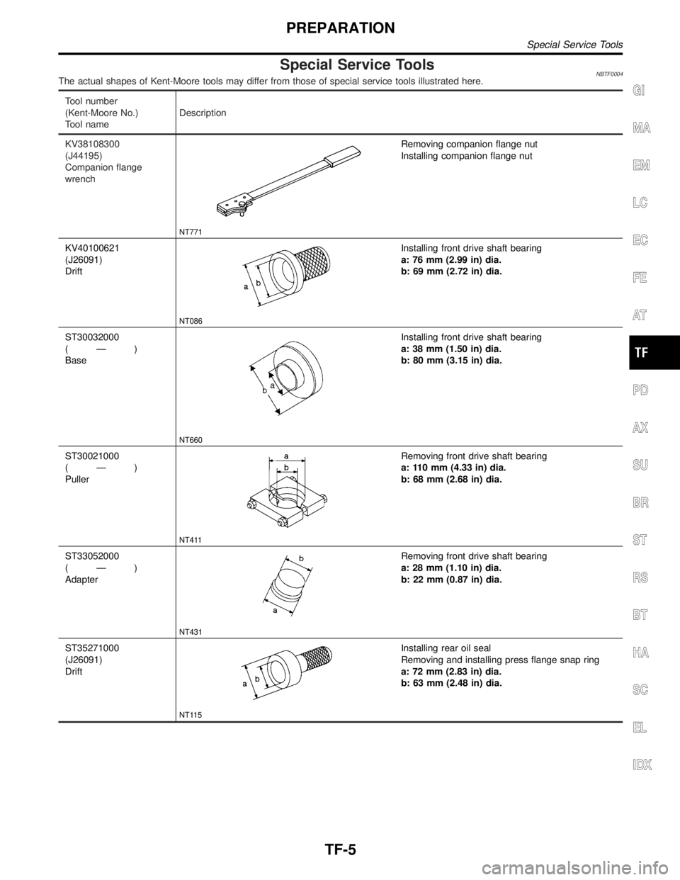
Special Service ToolsNBTF0004The actual shapes of Kent-Moore tools may differ from those of special service tools illustrated here.
Tool number
(Kent-Moore No.)
Tool nameDescription
KV38108300
(J44195)
Companion flange
wrench
NT771
Removing companion flange nut
Installing companion flange nut
KV40100621
(J26091)
Drift
NT086
Installing front drive shaft bearing
a: 76 mm (2.99 in) dia.
b: 69 mm (2.72 in) dia.
ST30032000
(Ð)
Base
NT660
Installing front drive shaft bearing
a: 38 mm (1.50 in) dia.
b: 80 mm (3.15 in) dia.
ST30021000
(Ð)
Puller
NT411
Removing front drive shaft bearing
a: 110 mm (4.33 in) dia.
b: 68 mm (2.68 in) dia.
ST33052000
(Ð)
Adapter
NT431
Removing front drive shaft bearing
a: 28 mm (1.10 in) dia.
b: 22 mm (0.87 in) dia.
ST35271000
(J26091)
Drift
NT115
Installing rear oil seal
Removing and installing press flange snap ring
a: 72 mm (2.83 in) dia.
b: 63 mm (2.48 in) dia.
GI
MA
EM
LC
EC
FE
AT
PD
AX
SU
BR
ST
RS
BT
HA
SC
EL
IDX
PREPARATION
Special Service Tools
TF-5
Page 2241 of 2395
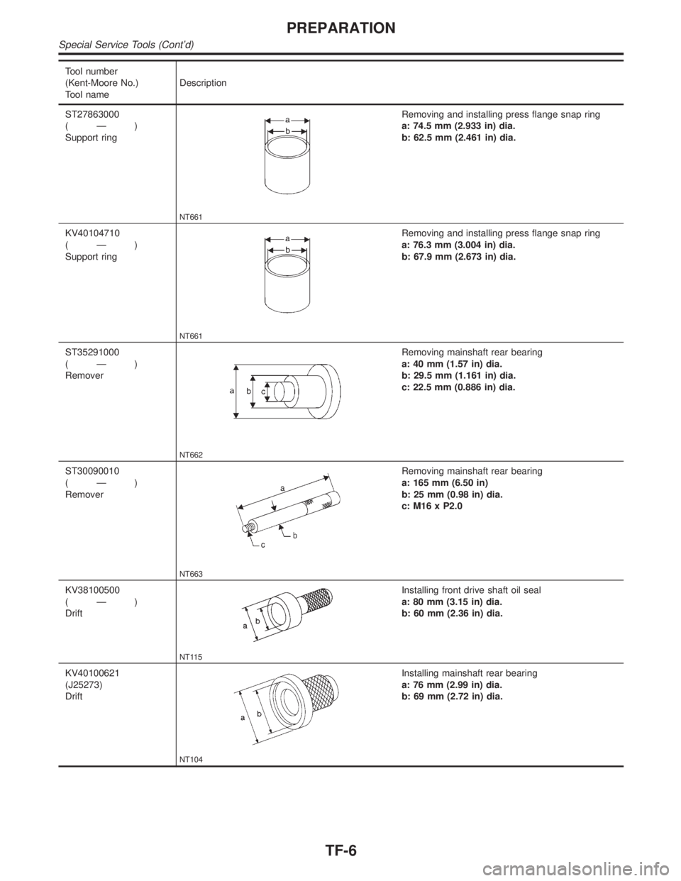
Tool number
(Kent-Moore No.)
Tool nameDescription
ST27863000
(Ð)
Support ring
NT661
Removing and installing press flange snap ring
a: 74.5 mm (2.933 in) dia.
b: 62.5 mm (2.461 in) dia.
KV40104710
(Ð)
Support ring
NT661
Removing and installing press flange snap ring
a: 76.3 mm (3.004 in) dia.
b: 67.9 mm (2.673 in) dia.
ST35291000
(Ð)
Remover
NT662
Removing mainshaft rear bearing
a: 40 mm (1.57 in) dia.
b: 29.5 mm (1.161 in) dia.
c: 22.5 mm (0.886 in) dia.
ST30090010
(Ð)
Remover
NT663
Removing mainshaft rear bearing
a: 165 mm (6.50 in)
b: 25 mm (0.98 in) dia.
c: M16 x P2.0
KV38100500
(Ð)
Drift
NT115
Installing front drive shaft oil seal
a: 80 mm (3.15 in) dia.
b: 60 mm (2.36 in) dia.
KV40100621
(J25273)
Drift
NT104
Installing mainshaft rear bearing
a: 76 mm (2.99 in) dia.
b: 69 mm (2.72 in) dia.
PREPARATION
Special Service Tools (Cont'd)
TF-6