brake INFINITI QX4 2001 Factory Workshop Manual
[x] Cancel search | Manufacturer: INFINITI, Model Year: 2001, Model line: QX4, Model: INFINITI QX4 2001Pages: 2395, PDF Size: 43.2 MB
Page 295 of 2395

SAT988A
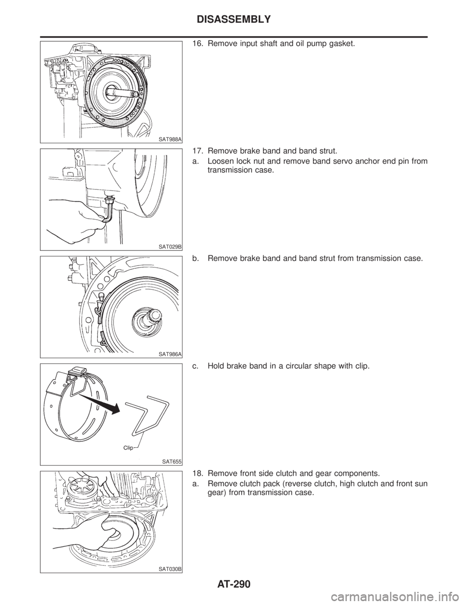
16. Remove input shaft and oil pump gasket.
SAT029B
17. Remove brake band and band strut.
a. Loosen lock nut and remove band servo anchor end pin from
transmission case.
SAT986A
b. Remove brake band and band strut from transmission case.
SAT655
c. Hold brake band in a circular shape with clip.
SAT030B
18. Remove front side clutch and gear components.
a. Remove clutch pack (reverse clutch, high clutch and front sun
gear) from transmission case.
DISASSEMBLY
AT-290
Page 329 of 2395

Low & Reverse Brake
COMPONENTSNBAT0136
SAT160K
SAT872A
DISASSEMBLYNBAT01371. Check operation of low and reverse brake.
a. Install seal ring onto oil pump cover and install reverse clutch.
Apply compressed air to oil hole.
b. Check to see that retaining plate moves to snap ring.
c. If retaining plate does not contact snap ring,
ID-ring might be damaged.
IOil seal might be damaged.
IFluid might be leaking past piston check ball.
SAT873A
2. Remove snap ring, low and reverse brake drive plates, driven
plates and dish plate.
REPAIR FOR COMPONENT PARTS
Low & Reverse Brake
AT-324
Page 330 of 2395

SAT382I
3. Remove low one-way clutch inner race, spring retainer and
return spring from transmission case.
4. Remove seal rings from low one-way clutch inner race.
5. Remove needle bearing from low one-way clutch inner race.
SAT876A
6. Remove low and reverse brake piston using compressed air.
7. Remove oil seal and D-ring from piston.
INSPECTIONNBAT0138Low and Reverse Brake Snap Ring and Spring RetainerNBAT0138S01ICheck for deformation, or damage.
SAT829A
Low and Reverse Brake Return SpringsNBAT0138S02ICheck for deformation or damage. Also measure free length
and outside diameter.
Inspection standard:
Refer to SDS, AT-357.
SAT845A
Low and Reverse Brake Drive PlatesNBAT0138S03ICheck facing for burns, cracks or damage.
IMeasure thickness of facing.
Thickness of drive plate:
Standard value
Model 4EX16 (2WD)
1.90 - 2.05 mm (0.075 - 0.081 in)
Model 4EX17, 4EX23 (4WD)
1.52 - 1.67 mm (0.0598 - 0.0657 in)
Wear limit
GI
MA
EM
LC
EC
FE
TF
PD
AX
SU
BR
ST
RS
BT
HA
SC
EL
IDX
REPAIR FOR COMPONENT PARTS
Low & Reverse Brake (Cont'd)
AT-325
Page 331 of 2395

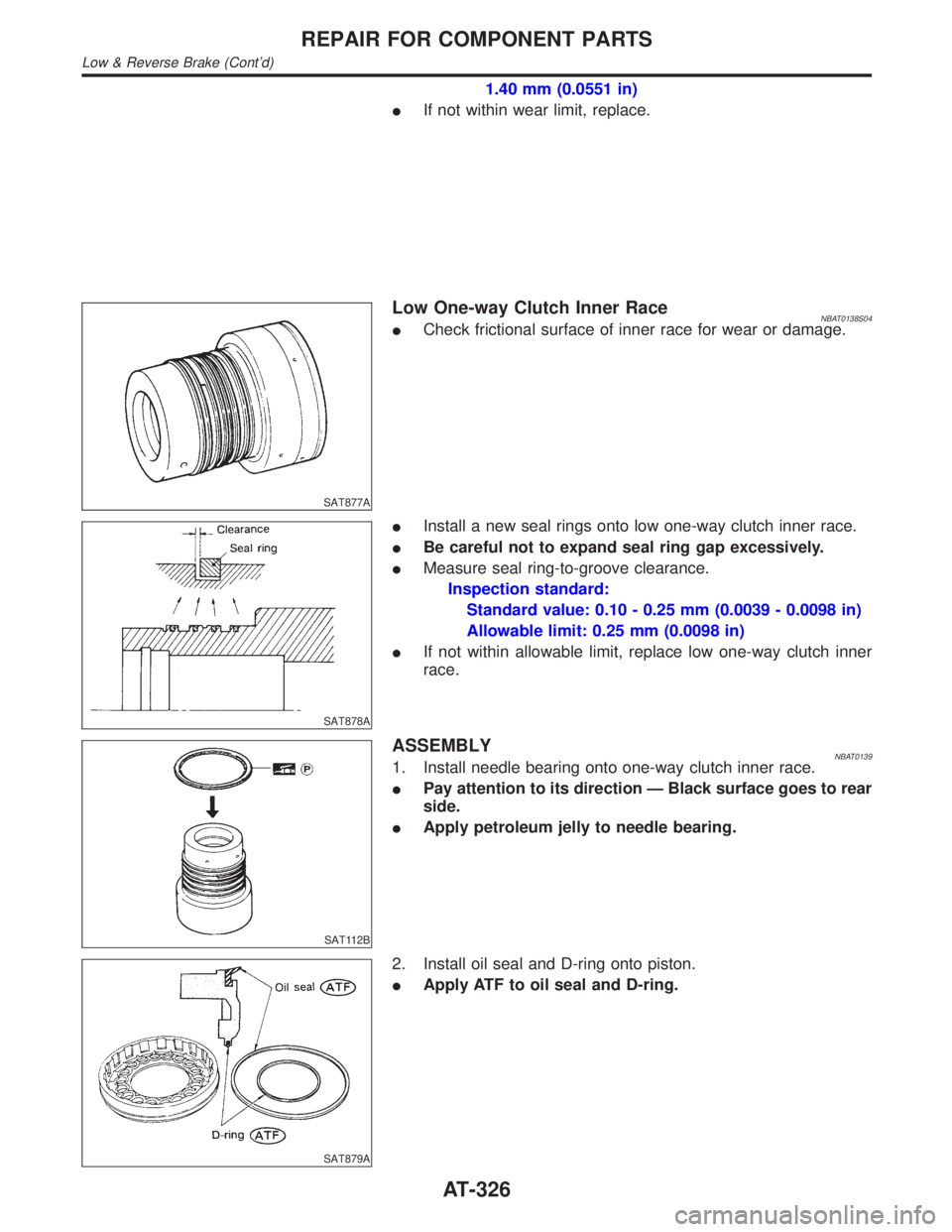
1.40 mm (0.0551 in)
IIf not within wear limit, replace.
SAT877A
Low One-way Clutch Inner RaceNBAT0138S04ICheck frictional surface of inner race for wear or damage.
SAT878A
IInstall a new seal rings onto low one-way clutch inner race.
IBe careful not to expand seal ring gap excessively.
IMeasure seal ring-to-groove clearance.
Inspection standard:
Standard value: 0.10 - 0.25 mm (0.0039 - 0.0098 in)
Allowable limit: 0.25 mm (0.0098 in)
IIf not within allowable limit, replace low one-way clutch inner
race.
SAT112B
ASSEMBLYNBAT01391. Install needle bearing onto one-way clutch inner race.
IPay attention to its direction Ð Black surface goes to rear
side.
IApply petroleum jelly to needle bearing.
SAT879A
2. Install oil seal and D-ring onto piston.
IApply ATF to oil seal and D-ring.
REPAIR FOR COMPONENT PARTS
Low & Reverse Brake (Cont'd)
AT-326
Page 332 of 2395

SAT880A
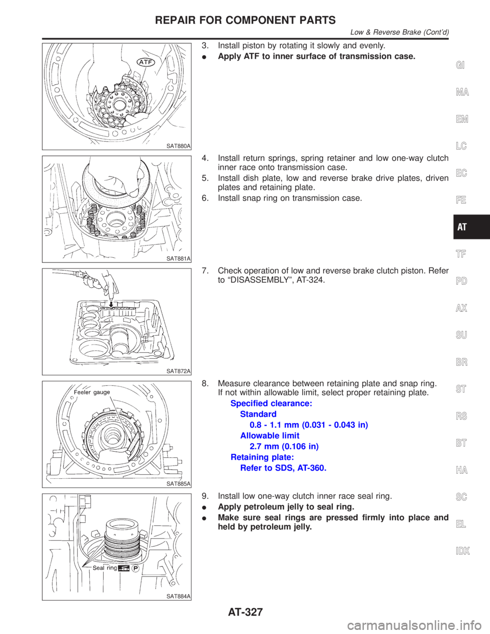
3. Install piston by rotating it slowly and evenly.
IApply ATF to inner surface of transmission case.
SAT881A
4. Install return springs, spring retainer and low one-way clutch
inner race onto transmission case.
5. Install dish plate, low and reverse brake drive plates, driven
plates and retaining plate.
6. Install snap ring on transmission case.
SAT872A
7. Check operation of low and reverse brake clutch piston. Refer
to ªDISASSEMBLYº, AT-324.
SAT885A
8. Measure clearance between retaining plate and snap ring.
If not within allowable limit, select proper retaining plate.
Specified clearance:
Standard
0.8 - 1.1 mm (0.031 - 0.043 in)
Allowable limit
2.7 mm (0.106 in)
Retaining plate:
Refer to SDS, AT-360.
SAT884A
9. Install low one-way clutch inner race seal ring.
IApply petroleum jelly to seal ring.
IMake sure seal rings are pressed firmly into place and
held by petroleum jelly.
GI
MA
EM
LC
EC
FE
TF
PD
AX
SU
BR
ST
RS
BT
HA
SC
EL
IDX
REPAIR FOR COMPONENT PARTS
Low & Reverse Brake (Cont'd)
AT-327
Page 354 of 2395

SAT983A
c. Install original thrust washer on oil pump. Place shim setting
gauge legs onto machined surface of oil pump assembly. Allow
gauging plunger to rest on thrust washer. Lock plunger in place
with set screw.
SAT984A
d. Use feeler gauge to measure gap between gauging plunger
and gauging cylinder. This measurement should give you exact
reverse clutch drum end play.
Reverse clutch drum end play ªT
2º:
0.55 - 0.90 mm (0.0217 - 0.0354 in)
IIf end play is out of specification, decrease or increase thick-
ness of oil pump thrust washer as necessary.
Available oil pump thrust washer:
Refer to SDS, AT-361.
SAT985A
Assembly (2)NBAT01571. Install brake band and band strut.
a. Install band strut on brake band.
IApply petroleum jelly to band strut.
SAT986A
b. Place brake band on periphery of reverse clutch drum, and
insert band strut into end of band servo piston stem.
SAT987A
c. Install anchor end bolt on transmission case. Then, tighten
anchor end bolt just enough so that reverse clutch drum (clutch
pack) will not tilt forward.
GI
MA
EM
LC
EC
FE
TF
PD
AX
SU
BR
ST
RS
BT
HA
SC
EL
IDX
ASSEMBLY
Adjustment (Cont'd)
AT-349
Page 357 of 2395

SAT001B
7. Install turbine revolution sensor.
8. Adjust brake band.
a. Tighten anchor end bolt to specified torque.
Anchor end bolt:
:4-6N´m(0.4 - 0.6 kg-m, 35 - 52 in-lb)
b. Back off anchor end bolt two and a half turns.
SAT002B
c. While holding anchor end bolt, tighten lock nut.
Ancher end bolt nut:
: 41 - 50 N´m (4.1 - 5.2 kg-m, 30 - 37 ft-lb)
SAT115B
9. Install terminal cord assembly.
a. Install O-ring on terminal cord assembly.
IApply petroleum jelly to O-ring.
b. Compress terminal cord assembly stopper and install terminal
cord assembly on transmission case.
SAT004BA
10. Install control valve assembly.
a. Install accumulator piston return springs B, C and D.
Free length of return springs:
Refer to SDS, AT-357.
SAT005B
b. Install manual valve on control valve.
IApply ATF to manual valve.
ASSEMBLY
Assembly (2) (Cont'd)
AT-352
Page 362 of 2395

Return SpringsNBAT0165Unit: mm (in)
PartsItem
Part No.* Free length Outer diameter
Control valveUpper body1 Torque converter relief valve spring 31742-41X23 38.0 (1.496) 9.0 (0.354)
2 Pressure regulator valve spring 31742-41X24 44.02 (1.7331) 14.0 (0.551)
3 Pressure modifier valve spring 31742-41X19 31.95 (1.2579) 6.8 (0.268)
Ð Accumulator control valve spring Ð Ð Ð
4 Shuttle shift valve D spring 31762-41X01 25.0 (0.984) 7.0 (0.276)
5 4-2 sequence valve spring 31756-41X00 29.1 (1.146) 6.95 (0.2736)
6 Shift valve B spring 31762-41X01 25.0 (0.984) 7.0 (0.276)
7 4-2 relay valve spring 31756-41X00 29.1 (1.146) 6.95 (0.2736)
8 Shift valve A spring 31762-41X01 25.0 (0.984) 7.0 (0.276)
9 Overrun clutch control valve spring 31762-41X03 23.6 (0.929) 7.0 (0.276)
10 Overrun clutch reducing valve spring 31742-41X14 38.9 (1.531) 7.0 (0.276)
11 Shuttle shift valve S spring 31762-41X04 51.0 (2.008) 5.65 (0.2224)
12 Pilot valve spring 31742-41X13 25.7 (1.012) 9.0 (0.354)
13 Torque converter clutch control valve spring 31742-41X22 18.5 (0.728) 13.0 (0.512)
Lower body1 Modifier accumulator piston spring 31742-27X70 31.4 (1.236) 9.8 (0.386)
2 1st reducing valve spring 31756-60X00 20.5 (0.807) 7.0 (0.276)
3 3-2 timing valve spring 31742-41X06 23.0 (0.906) 6.7 (0.264)
4 Servo charger valve spring 31742-41X06 23.0 (0.906) 6.7 (0.264)
Reverse clutch Ð 31505-41X07 Ð Ð
High clutch10 pcs31521-41X03
(Assembly)24.2 (0.9528) 11.6 (0.457)
Forward clutch (Overrun clutch) 20 pcs31521-41X04
(Assembly)35.77 (1.4083) 9.7 (0.382)
Low & reverse brake 18 pcs31655-41X00
(Assembly)22.3 (0.878) 11.2 (0.441)
Band servoSpring A 31605-4AX03 45.6 (1.795) 34.3 (1.350)
Spring B 31605-41X01 29.7 (1.169) 27.6 (1.087)
AccumulatorAccumulator A 31605-41X02 43.0 (1.693) 18.0 (0.709)
Accumulator B 31605-41X14 47.6 (1.874) 26.5 (1.043)
Accumulator C 31605-41X09 45.0 (1.772) 29.3 (1.154)
Accumulator D 31605-41X06 58.4 (2.299) 17.3 (0.681)
GI
MA
EM
LC
EC
FE
TF
PD
AX
SU
BR
ST
RS
BT
HA
SC
EL
IDX
SERVICE DATA AND SPECIFICATIONS (SDS)
Return Springs
AT-357
Page 363 of 2395

Accumulator O-ringNBAT0166
AccumulatorDiameter mm (in)
ABC D
Small diameter end 29 (1.14) 32 (1.26) 45 (1.77) 29 (1.14)
Large diameter end 45 (1.77) 50 (1.97) 50 (1.97) 45 (1.77)
Clutches and BrakesNBAT0167REVERSE CLUTCHNBAT0167S01
Code number4EX16 4EX17
Number of drive plates2
Number of driven plates2
Thickness of drive plate mm (in)Standard 1.90 - 2.05 (0.0748 - 0.0807)
Wear limit 1.80 (0.0709)
Clearance mm (in)Standard 0.5 - 0.8 (0.020 - 0.031)
Allowable limit 1.2 (0.047)
Thickness of retaining plateThickness mm (in) Part number*
4.6 (0.181)
4.8 (0.189)
5.0 (0.197)
5.2 (0.205)
5.4 (0.213)31537-42X20
31537-42X21
31537-42X22
31537-42X23
31537-42X24
HIGH CLUTCHNBAT0167S02
Code number4EX16 4EX17
Number of drive plates5
Number of driven plates6
Thickness of drive plate mm (in)Standard 1.52 - 1.67 (0.0598 - 0.0657)
Wear limit 1.40 (0.0551)
Clearance mm (in)Standard 1.8 - 2.2 (0.071 - 0.087)
Allowable limit 3.2 (0.126)
Thickness of retaining plateThickness mm (in) Part number*
4.0 (0.157)
4.2 (0.165)
4.4 (0.173)
4.6 (0.181)
4.8 (0.189)
5.0 (0.197)31537-41X63
31537-41X64
31537-41X65
31537-41X66
31537-41X67
31537-41X68
SERVICE DATA AND SPECIFICATIONS (SDS)
Accumulator O-ring
AT-358
Page 364 of 2395

FORWARD CLUTCHNBAT0167S03
Code number 4EX16 4EX17
Number of drive plates 7 8
Number of driven plates 7 8
Thickness of drive
plate mm (in)Standard 1.52 - 1.67 (0.0598 - 0.0657)
Wear limit 1.40 (0.0551)
Clearance mm (in)Standard 0.35 - 0.75 (0.0138 - 0.0295)
Allowable limit 2.15 (0.0846) 2.35 (0.0925)
Thickness of retaining plateThickness mm (in) Part number* Thickness mm (in) Part number*
4.6 (0.181)
4.8 (0.189)
5.0 (0.197)
5.2 (0.205)
5.4 (0.213)
5.6 (0.220)31537-42X13
31537-42X14
31537-42X15
31537-4AX00
31537-4AX01
31537-4AX024.2 (0.165)
4.4 (0.173)
4.6 (0.181)
4.8 (0.189)
5.0 (0.197)
5.2 (0.205)
5.4 (0.213)31537-42X11
31537-42X12
31537-42X13
31537-42X14
31537-42X15
31537-4AX00
31537-4AX01
OVERRUN CLUTCHNBAT0167S04
Code number4EX16 4EX17
Number of drive plates3
Number of driven plates5
Thickness of drive plate mm (in)Standard 1.90 - 2.05 (0.0748 - 0.0807)
Wear limit 1.80 (0.0709)
Clearance mm (in)Standard 1.0 - 1.4 (0.039 - 0.055)
Allowable limit 2.0 (0.079)
Thickness of retaining plateThickness mm (in) Part number*
4.2 (0.165)
4.4 (0.173)
4.6 (0.181)
4.8 (0.189)
5.0 (0.197)31537-41X80
31537-41X81
31537-41X82
31537-41X83
31537-41X84
GI
MA
EM
LC
EC
FE
TF
PD
AX
SU
BR
ST
RS
BT
HA
SC
EL
IDX
SERVICE DATA AND SPECIFICATIONS (SDS)
Clutches and Brakes (Cont'd)
AT-359