oil INFINITI QX4 2001 Factory Repair Manual
[x] Cancel search | Manufacturer: INFINITI, Model Year: 2001, Model line: QX4, Model: INFINITI QX4 2001Pages: 2395, PDF Size: 43.2 MB
Page 309 of 2395

SAT676A
Pilot FilterNBAT0118S03ICheck to make sure that filter is not clogged or damaged.
SAT149G
Torque Converter Clutch Solenoid ValveNBAT0118S04ICheck that filter is not clogged or damaged.
IMeasure resistance. Refer to ªComponent Inspectionº, AT-152.
Line Pressure Solenoid ValveNBAT0118S05ICheck that filter is not clogged or damaged.
IMeasure resistance. Refer to ªComponent Inspectionº, AT-167.
SAT095B
3-Unit Solenoid Assembly (Overrun Clutch Solenoid
Valve and Shift Solenoid Valves A and B)
NBAT0118S06IMeasure resistance of each solenoid. Refer to ªComponent
Inspectionº, AT-171, AT-175 and AT-189.
SAT096BA
A/T Fluid Temperature Sensor and SwitchNBAT0118S07IMeasure resistance. Refer to ªComponent Inspectionº, AT-110
and AT-264.
SAT671A
ASSEMBLYNBAT01191. Install upper and lower bodies.
a. Place oil circuit of upper body face up. Install steel balls in their
proper positions.
REPAIR FOR COMPONENT PARTS
Control Valve Assembly (Cont'd)
AT-304
Page 310 of 2395

SAT681A
b. Install reamer bolts from bottom of upper body.
SAT682A
c. Place oil circuit of lower body face up. Install orifice check
spring, orifice check valve and pilot filter.
SAT197B
d. Install lower separator plate on lower body.
e. Install and temporarily tighten support plates, A/T fluid tem-
perature sensor and tube brackets.
SAT198B
f. Temporarily assemble lower and upper bodies, using reamer
bolt as a guide.
IBe careful not to dislocate or drop steel balls, orifice
check spring, orifice check valve and pilot filter.
GI
MA
EM
LC
EC
FE
TF
PD
AX
SU
BR
ST
RS
BT
HA
SC
EL
IDX
REPAIR FOR COMPONENT PARTS
Control Valve Assembly (Cont'd)
AT-305
Page 319 of 2395

Reverse Clutch
COMPONENTSNBAT0128
SAT157K
SAT841A
DISASSEMBLYNBAT01291. Check operation of reverse clutch.
a. Install seal ring onto oil pump cover and install reverse clutch.
Apply compressed air to oil hole.
b. Check to see that retaining plate moves to snap ring.
c. If retaining plate does not contact snap ring,
ID-ring might be damaged.
IOil seal might be damaged.
IFluid might be leaking past piston check ball.
SAT842A
2. Remove drive plates, driven plates, retaining plate, dish plate
and snap ring.
REPAIR FOR COMPONENT PARTS
Reverse Clutch
AT-314
Page 320 of 2395

SAT524G
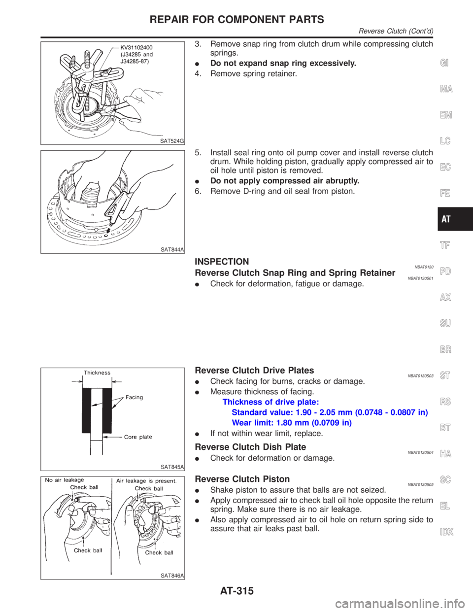
3. Remove snap ring from clutch drum while compressing clutch
springs.
IDo not expand snap ring excessively.
4. Remove spring retainer.
SAT844A
5. Install seal ring onto oil pump cover and install reverse clutch
drum. While holding piston, gradually apply compressed air to
oil hole until piston is removed.
IDo not apply compressed air abruptly.
6. Remove D-ring and oil seal from piston.
INSPECTIONNBAT0130Reverse Clutch Snap Ring and Spring RetainerNBAT0130S01ICheck for deformation, fatigue or damage.
SAT845A
Reverse Clutch Drive PlatesNBAT0130S03ICheck facing for burns, cracks or damage.
IMeasure thickness of facing.
Thickness of drive plate:
Standard value: 1.90 - 2.05 mm (0.0748 - 0.0807 in)
Wear limit: 1.80 mm (0.0709 in)
IIf not within wear limit, replace.
Reverse Clutch Dish PlateNBAT0130S04ICheck for deformation or damage.
SAT846A
Reverse Clutch PistonNBAT0130S05IShake piston to assure that balls are not seized.
IApply compressed air to check ball oil hole opposite the return
spring. Make sure there is no air leakage.
IAlso apply compressed air to oil hole on return spring side to
assure that air leaks past ball.
GI
MA
EM
LC
EC
FE
TF
PD
AX
SU
BR
ST
RS
BT
HA
SC
EL
IDX
REPAIR FOR COMPONENT PARTS
Reverse Clutch (Cont'd)
AT-315
Page 321 of 2395

SAT847A
ASSEMBLYNBAT01311. Install D-ring and oil seal on piston.
IApply ATF to both parts.
SAT848A
2. Install piston assembly by turning it slowly and evenly.
IApply ATF to inner surface of drum.
3. Install spring retainer.
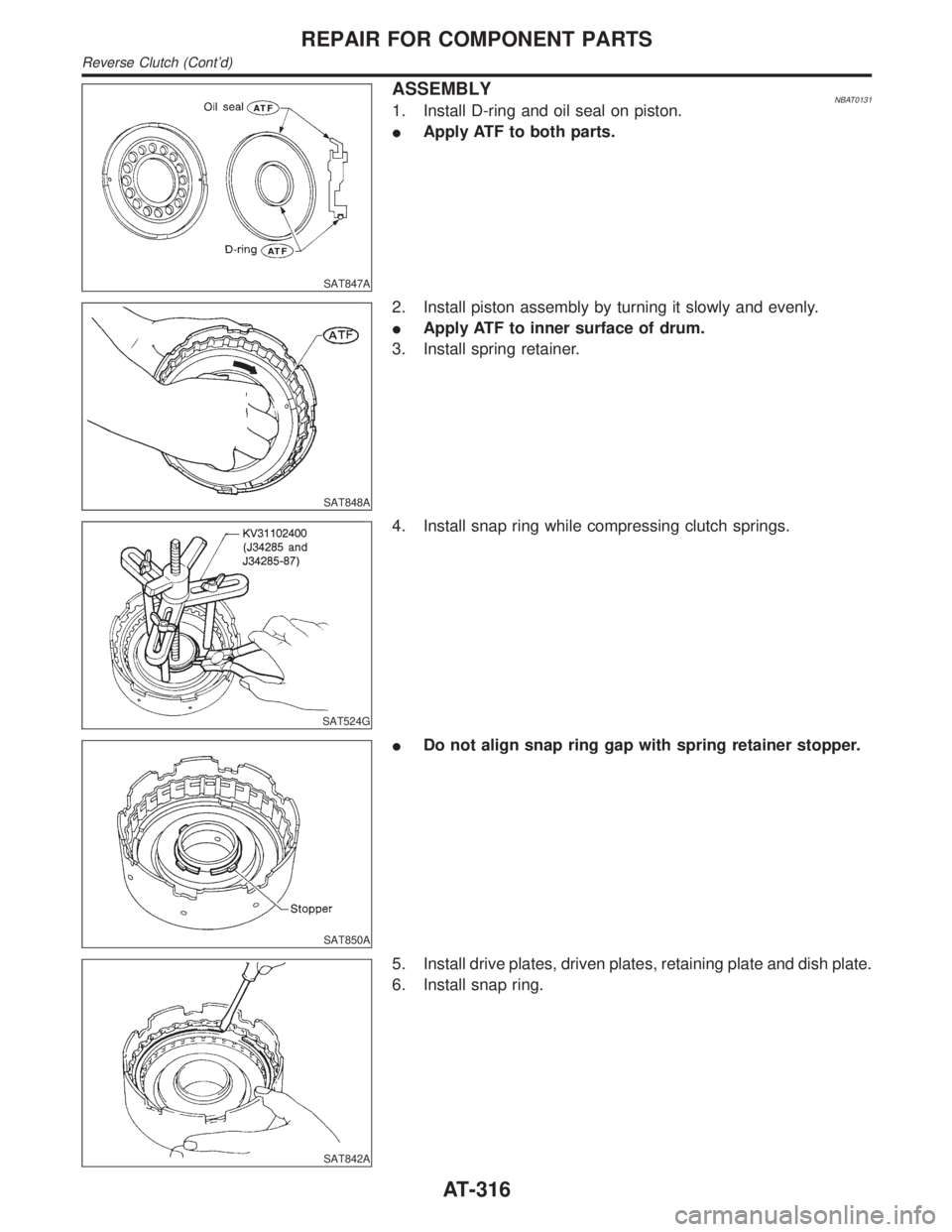
SAT524G
4. Install snap ring while compressing clutch springs.
SAT850A
IDo not align snap ring gap with spring retainer stopper.
SAT842A
5. Install drive plates, driven plates, retaining plate and dish plate.
6. Install snap ring.
REPAIR FOR COMPONENT PARTS
Reverse Clutch (Cont'd)
AT-316
Page 326 of 2395

SAT860A
DISASSEMBLY AND ASSEMBLYNBAT0135Forward and overrun clutches are serviced essentially the same
way as reverse clutch is serviced. However, note the following
exceptions.
ICheck of forward clutch operation
SAT861A
ICheck of overrun clutch operation
SAT865A
IRemoval of forward clutch drum
Remove forward clutch drum from transmission case by hold-
ing snap ring.
SAT862A
IRemoval of forward clutch and overrun clutch pistons
a) While holding overrun clutch piston, gradually apply com-
pressed air to oil hole.
SAT863A
b) Remove overrun clutch from forward clutch.
GI
MA
EM
LC
EC
FE
TF
PD
AX
SU
BR
ST
RS
BT
HA
SC
EL
IDX
REPAIR FOR COMPONENT PARTS
Forward and Overrun Clutches (Cont'd)
AT-321
Page 329 of 2395

Low & Reverse Brake
COMPONENTSNBAT0136
SAT160K
SAT872A
DISASSEMBLYNBAT01371. Check operation of low and reverse brake.
a. Install seal ring onto oil pump cover and install reverse clutch.
Apply compressed air to oil hole.
b. Check to see that retaining plate moves to snap ring.
c. If retaining plate does not contact snap ring,
ID-ring might be damaged.
IOil seal might be damaged.
IFluid might be leaking past piston check ball.
SAT873A
2. Remove snap ring, low and reverse brake drive plates, driven
plates and dish plate.
REPAIR FOR COMPONENT PARTS
Low & Reverse Brake
AT-324
Page 330 of 2395

SAT382I
3. Remove low one-way clutch inner race, spring retainer and
return spring from transmission case.
4. Remove seal rings from low one-way clutch inner race.
5. Remove needle bearing from low one-way clutch inner race.
SAT876A
6. Remove low and reverse brake piston using compressed air.
7. Remove oil seal and D-ring from piston.
INSPECTIONNBAT0138Low and Reverse Brake Snap Ring and Spring RetainerNBAT0138S01ICheck for deformation, or damage.
SAT829A
Low and Reverse Brake Return SpringsNBAT0138S02ICheck for deformation or damage. Also measure free length
and outside diameter.
Inspection standard:
Refer to SDS, AT-357.
SAT845A
Low and Reverse Brake Drive PlatesNBAT0138S03ICheck facing for burns, cracks or damage.
IMeasure thickness of facing.
Thickness of drive plate:
Standard value
Model 4EX16 (2WD)
1.90 - 2.05 mm (0.075 - 0.081 in)
Model 4EX17, 4EX23 (4WD)
1.52 - 1.67 mm (0.0598 - 0.0657 in)
Wear limit
GI
MA
EM
LC
EC
FE
TF
PD
AX
SU
BR
ST
RS
BT
HA
SC
EL
IDX
REPAIR FOR COMPONENT PARTS
Low & Reverse Brake (Cont'd)
AT-325
Page 331 of 2395

1.40 mm (0.0551 in)
IIf not within wear limit, replace.
SAT877A
Low One-way Clutch Inner RaceNBAT0138S04ICheck frictional surface of inner race for wear or damage.
SAT878A
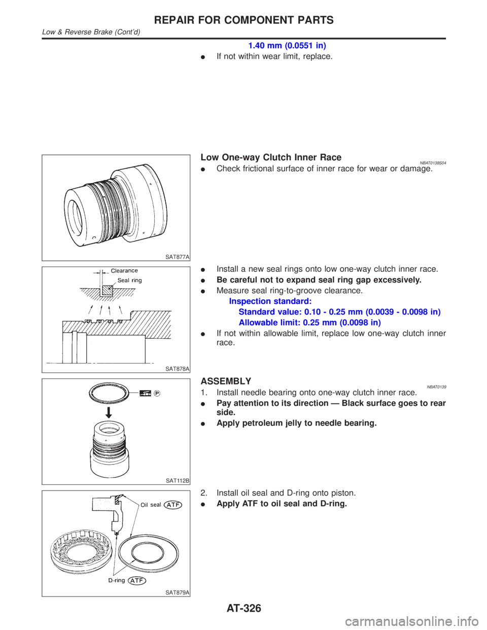
IInstall a new seal rings onto low one-way clutch inner race.
IBe careful not to expand seal ring gap excessively.
IMeasure seal ring-to-groove clearance.
Inspection standard:
Standard value: 0.10 - 0.25 mm (0.0039 - 0.0098 in)
Allowable limit: 0.25 mm (0.0098 in)
IIf not within allowable limit, replace low one-way clutch inner
race.
SAT112B
ASSEMBLYNBAT01391. Install needle bearing onto one-way clutch inner race.
IPay attention to its direction Ð Black surface goes to rear
side.
IApply petroleum jelly to needle bearing.
SAT879A
2. Install oil seal and D-ring onto piston.
IApply ATF to oil seal and D-ring.
REPAIR FOR COMPONENT PARTS
Low & Reverse Brake (Cont'd)
AT-326
Page 338 of 2395

SAT905A
8. After installing, check to assure that forward clutch hub rotates
clockwise.
Band Servo Piston Assembly
COMPONENTSNBAT0148
SAT161K
SAT909A
DISASSEMBLYNBAT01491. Block one oil hole in OD servo piston retainer and the center
hole in OD band servo piston.
2. Apply compressed air to the other oil hole in piston retainer to
remove OD band servo piston from retainer.
3. Remove D-ring from OD band servo piston.
SAT910A
4. Remove band servo piston assembly from servo piston
retainer by pushing it forward.
GI
MA
EM
LC
EC
FE
TF
PD
AX
SU
BR
ST
RS
BT
HA
SC
EL
IDX
REPAIR FOR COMPONENT PARTS
Rear Internal Gear and Forward Clutch Hub (Cont'd)
AT-333