Idle air INFINITI QX4 2001 Factory Service Manual
[x] Cancel search | Manufacturer: INFINITI, Model Year: 2001, Model line: QX4, Model: INFINITI QX4 2001Pages: 2395, PDF Size: 43.2 MB
Page 61 of 2395

4. 4-3. Cruise testAT-67
AT-71
Part-1
l8. Vehicle Cannot Be Started From D
1, AT-233.
l9. A/T Does Not Shift: D
1,D2Or Does Not Kickdown: D4,D2, AT-236.
l10. A/T Does Not Shift: D
2,D3, AT-239.
l11. A/T Does Not Shift: D
3,D4, AT-242.
l12. A/T Does Not Perform Lock-up, AT-245.
l13. A/T Does Not Hold Lock-up Condition, AT-247.
l14. Lock-up Is Not Released, AT-249.
l15. Engine Speed Does Not Return To Idle (Light Braking D
4,D3), AT-250.
Part-2AT-75
l16. Vehicle Does Not Start From D
1, AT-252.
l9. A/T Does Not Shift: D
1,D2Or Does Not Kickdown: D4,D2, AT-236.
l10. A/T Does Not Shift: D
2,D3, AT-239.
l11. A/T Does Not Shift: D
3,D4, AT-242.
Part-3AT-77
l17. A/T Does Not Shift: D
4,D3When Overdrive Control Switch ªONº,ªOFFº, AT-253
l15. Engine Speed Does Not Return To Idle (Engine Brake In D
3), AT-250.
l18. A/T Does Not Shift: D
3,22, When Selector Lever ªDº,ª2º Position, AT-254.
l15. Engine Speed Does Not Return To Idle (Engine Brake In 2
2), AT-250.
l19. A/T Does Not Shift: 2
2,11, When Selector Lever ª2º,ª1º Position, AT-255.
l20. Vehicle Does Not Decelerate By Engine Brake, AT-256.
lSELF-DIAGNOSTIC PROCEDURE Ð Mark detected items.
lDTC P0705 PNP switch, AT-99.
lDTC P0710 A/T fluid temperature sensor, AT-105.
lDTC P0720 Vehicle speed sensor´A/T (Revolution sensor), AT-111.
lDTC P0725 Engine speed signal, AT-116.
lDTC P0740 Torque converter clutch solenoid valve, AT-148.
lDTC P0745 Line pressure solenoid valve, AT-162.
lDTC P0750 Shift solenoid valve A, AT-168.
lDTC P0755 Shift solenoid valve B, AT-172.
lDTC P1705 Throttle position sensor, AT-176.
lDTC P1760 Overrun clutch solenoid valve, AT-185.
lDTC BATT/FLUID TEMP SEN (A/T fluid temperature sensor and TCM power source), AT-190.
lDTC Vehicle speed sensor´MTR, AT-197.
lDTC Turbine revolution sensor, AT-202.
lDTC A/T communication line, AT-207.
lDTC Control unit (RAM), control unit (ROM), AT-211.
lDTC Control unit (EEP ROM), AT-213.
lPNP, overdrive control and throttle position switches, AT-257.
lBattery
lOthers
5.lFor self-diagnosis NG items, inspect each component. Repair or replace the damaged parts. AT-38
6.lPerform all ROAD TEST and re-mark required procedures. AT-63
7.lPerform DTC CONFIRMATION PROCEDURE for following MIL indicating items and check out NG items.
Refer to EC-60, ªEmission-related Diagnostic Informationº.EC-60
lDTC (P0731, 1103) A/T 1st gear function, AT-120.
lDTC (P0732, 1104) A/T 2nd gear function, AT-126.
lDTC (P0733, 1105) A/T 3rd gear function, AT-132.
lDTC (P0734, 1106) A/T 4th gear function, AT-138.
lDTC (P0744, 1107) A/T TCC S/V function (lock-up), AT-153.
8.lPerform the Diagnostic Procedures for all remaining items marked NG. Repair or replace the damaged
parts.
Refer to the Symptom Chart when you perform the procedures. (The chart also shows some other possible
symptoms and the component inspection orders.)AT-92
AT-97
9.lErase DTC from TCM and ECM memories. AT-35
TROUBLE DIAGNOSIS Ð INTRODUCTION
Introduction (Cont'd)
AT-56
Page 255 of 2395

15. Engine Speed Does Not Return To Idle
(Light Braking D
4®D3)=NBAT0087SYMPTOM:
IEngine speed does not smoothly return to idle when A/T
shifts from D
4to D3.
IVehicle does not decelerate by engine brake when turning
overdrive control switch OFF.
IVehicle does not decelerate by engine brake when shifting
A/T from ªDº to ª2º position.
1 CHECK SELF-DIAGNOSTIC RESULTS
Does self-diagnosis show damage to overrun clutch solenoid valve circuit after cruise test?
SAT583I
YesorNo
Ye s©Check overrun clutch solenoid valve circuit. Refer to ªDTC P1760º, AT-185.
No©GO TO 2.
2 CHECK THROTTLE POSITION SENSOR
Check throttle position sensor. Refer to EC-174, ªDescriptionº.
SAT142K
OK or NG
OK©GO TO 3.
NG©Repair or replace throttle position sensor.
TROUBLE DIAGNOSES FOR SYMPTOMS
15. Engine Speed Does Not Return To Idle (Light Braking D4®D3)
AT-250
Page 256 of 2395
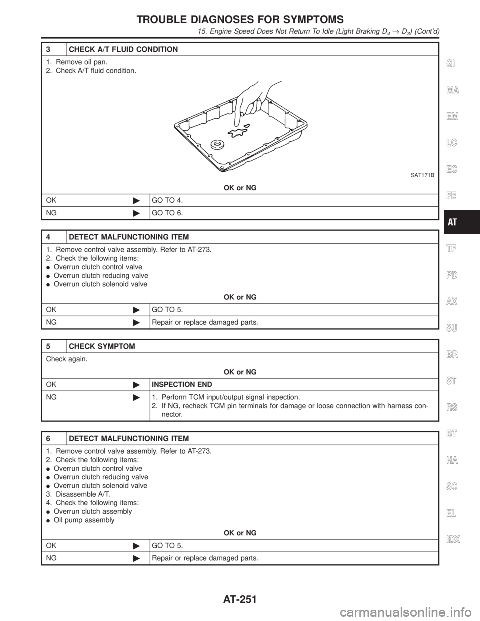
3 CHECK A/T FLUID CONDITION
1. Remove oil pan.
2. Check A/T fluid condition.
SAT171B
OK or NG
OK©GO TO 4.
NG©GO TO 6.
4 DETECT MALFUNCTIONING ITEM
1. Remove control valve assembly. Refer to AT-273.
2. Check the following items:
IOverrun clutch control valve
IOverrun clutch reducing valve
IOverrun clutch solenoid valve
OK or NG
OK©GO TO 5.
NG©Repair or replace damaged parts.
5 CHECK SYMPTOM
Check again.
OK or NG
OK©INSPECTION END
NG©1. Perform TCM input/output signal inspection.
2. If NG, recheck TCM pin terminals for damage or loose connection with harness con-
nector.
6 DETECT MALFUNCTIONING ITEM
1. Remove control valve assembly. Refer to AT-273.
2. Check the following items:
IOverrun clutch control valve
IOverrun clutch reducing valve
IOverrun clutch solenoid valve
3. Disassemble A/T.
4. Check the following items:
IOverrun clutch assembly
IOil pump assembly
OK or NG
OK©GO TO 5.
NG©Repair or replace damaged parts.
GI
MA
EM
LC
EC
FE
TF
PD
AX
SU
BR
ST
RS
BT
HA
SC
EL
IDX
TROUBLE DIAGNOSES FOR SYMPTOMS
15. Engine Speed Does Not Return To Idle (Light Braking D4®D3) (Cont'd)
AT-251
Page 478 of 2395
DUPLICATE THE NOISE AND TEST DRIVENBBT0024S02If possible, drive the vehicle with the customer until the noise is duplicated. Note any additional information on
the Diagnostic Worksheet regarding the conditions or location of the noise. This information can be used to
duplicate the same conditions when you confirm the repair.
If the noise can be duplicated easily during the test drive, to help identify the source of the noise, try to dupli-
cate the noise with the vehicle stopped by doing one or all of the following:
1) Close a door.
2) Tap or push/pull around the area where the noise appears to be coming from.
3) Rev the engine.
4) Use a floor jack to recreate vehicle ªtwistº.
5) At idle, apply engine load (electrical load, half-clutch on M/T model, drive position on A/T model).
6) Raise the vehicle on a hoist and hit a tire with a rubber hammer.
IDrive the vehicle and attempt to duplicate the conditions the customer states exist when the noise occurs.
IIf it is difficult to duplicate the noise, drive the vehicle slowly on an undulating or rough road to stress the
vehicle body.
CHECK RELATED SERVICE BULLETINSNBBT0024S03After verifying the customer concern or symptom, check ASIST for Technical Service Bulletins (TSBs) related
to that concern or symptom.
If a TSB relates to the symptom, follow the procedure to repair the noise.
LOCATE THE NOISE AND IDENTIFY THE ROOT CAUSENBBT0024S041. Narrow down the noise to a general area. To help pinpoint the source of the noise, use a listening tool
(Chassis Ear: J-39570, Engine Ear: J-39565 and mechanics stethoscope).
2. Narrow down the noise to a more specific area and identify the cause of the noise by:
Iremoving the components in the area that you suspect the noise is coming from.
Do not use too much force when removing clips and fasteners, otherwise clips and fastener can
be broken or lost during the repair, resulting in the creation of new noise.
Itapping or pushing/pulling the component that you suspect is causing the noise.
Do not tap or push/pull the component with excessive force, otherwise the noise will be eliminated
only temporarily.
Ifeeling for a vibration with your hand by touching the component(s) that you suspect is (are) causing the
noise.
Iplacing a piece of paper between components that you suspect are causing the noise.
Ilooking for loose components and contact marks.
Refer to ªGeneric Squeak and Rattle Troubleshootingº, BT-6.
REPAIR THE CAUSENBBT0024S05IIf the cause is a loose component, tighten the component securely.
IIf the cause is insufficient clearance between components:
þ separate components by repositioning or loosening and retightening the component, if possible.
þ insulate components with a suitable insulator such as urethane pads, foam blocks, felt cloth tape or ure-
thane tape. A Nissan Squeak and Rattle Kit (J-43980) is available through your authorized Nissan Parts
Department.
CAUTION:
Do not use excessive force as many components are constructed of plastic and may be damaged.
Always check with the Parts Department for the latest parts information.
The following materials are contained in the Nissan Squeak and Rattle Kit (J-43980). Each item can be ordered
separately as needed.
URETHANE PADS [1.5 mm (0.059 in) thick]
Insulates connectors, harness, etc.
76268-9E005: 100 x 135 mm (3.94 x 5.31 in)/76884-71L01: 60 x 85 mm (2.36 x 3.35 in)/76884-71L02: 15 x
25 mm (0.59 x 0.98 in)
INSULATOR (Foam blocks)
Insulates components from contact. Can be used to fill space behind a panel.
73982-9E000: 45 mm (1.77 in) thick, 50 x 50 mm (1.97 x 1.97 in)/73982-50Y00: 10 mm (0.39 in) thick, 50 x
50 mm (1.97 x 1.97 in)
INSULATOR (Light foam block)
GI
MA
EM
LC
EC
FE
AT
TF
PD
AX
SU
BR
ST
RS
HA
SC
EL
IDX
SQUEAK AND RATTLE TROUBLE DIAGNOSES
Work Flow (Cont'd)
BT-5
Page 536 of 2395
ENGINE CONTROL SYSTEM
SECTION
EC
CONTENTS
TROUBLE DIAGNOSIS - INDEX....................................8
Alphabetical & P No. Index for DTC ...........................8
PRECAUTIONS.............................................................14
Supplemental Restraint System (SRS)²AIR
BAG²and²SEAT BELT PRE-TENSIONER².............14
Precautions for On Board Diagnostic (OBD)
System of Engine and A/T.........................................14
Engine Fuel & Emission Control System ..................15
Precautions ................................................................16
Wiring Diagrams and Trouble Diagnosis ...................17
PREPARATION.............................................................18
Special Service Tools ................................................18
Commercial Service Tools .........................................18
ENGINE AND EMISSION CONTROL OVERALL
SYSTEM.........................................................................20
Engine Control Component Parts Location ...............20
Circuit Diagram ..........................................................24
System Diagram ........................................................25
Vacuum Hose Drawing ..............................................26
System Chart .............................................................27
ENGINE AND EMISSION BASIC CONTROL
SYSTEM DESCRIPTION...............................................28
Multiport Fuel Injection (MFI) System .......................28
Electronic Ignition (EI) System ..................................30
Air Conditioning Cut Control ......................................31
Fuel Cut Control (at no load & high engine
speed) ........................................................................32
Evaporative Emission System ...................................32
Positive Crankcase Ventilation ..................................38
BASIC SERVICE PROCEDURE...................................39
Fuel Pressure Release ..............................................39
Fuel Pressure Check .................................................39
Fuel Pressure Regulator Check ................................40
Injector .......................................................................41
How to Check Idle Speed and Ignition Timing ..........42
Idle Speed/Ignition Timing/Idle Mixture Ratio
Adjustment .................................................................43
Idle Air Volume Learning ...........................................57ON BOARD DIAGNOSTIC SYSTEM
DESCRIPTION...............................................................59
Introduction ................................................................59
Two Trip Detection Logic ...........................................59
Emission-related Diagnostic Information ...................60
Malfunction Indicator Lamp (MIL) ..............................74
OBD System Operation Chart ...................................75
CONSULT-II ...............................................................81
Generic Scan Tool (GST) ..........................................95
TROUBLE DIAGNOSIS - INTRODUCTION..................97
Introduction ................................................................97
Work Flow ..................................................................99
TROUBLE DIAGNOSIS - BASIC INSPECTION.........101
Basic Inspection.......................................................101
TROUBLE DIAGNOSIS - GENERAL
DESCRIPTION............................................................. 116
DTC Inspection Priority Chart.................................. 116
Fail-safe Chart ......................................................... 117
Symptom Matrix Chart ............................................. 118
CONSULT-II Reference Value in Data Monitor
Mode ........................................................................122
Major Sensor Reference Graph in Data Monitor
Mode ........................................................................124
ECM Terminals and Reference Value .....................127
TROUBLE DIAGNOSIS - SPECIFICATION VALUE..136
Description ...............................................................136
Testing Condition .....................................................136
Inspection Procedure ...............................................136
Diagnostic Procedure ..............................................137
TROUBLE DIAGNOSIS FOR INTERMITTENT
INCIDENT.....................................................................140
Description ...............................................................140
Diagnostic Procedure ..............................................140
TROUBLE DIAGNOSIS FOR POWER SUPPLY........141
ECM Terminals and Reference Value .....................141
Main Power Supply and Ground Circuit ..................142
DTC P0100 MASS AIR FLOW SENSOR (MAFS)......150
Component Description ...........................................150
GI
MA
EM
LC
FE
AT
TF
PD
AX
SU
BR
ST
RS
BT
HA
SC
EL
IDX
Page 540 of 2395
Possible Cause ........................................................ 411
Overall Function Check ........................................... 411
DTC P0464 FUEL LEVEL SENSOR CIRCUIT...........413
Component Description ...........................................413
On Board Diagnostic Logic......................................413
Possible Cause ........................................................413
DTC Confirmation Procedure ..................................413
Wiring Diagram ........................................................414
Diagnostic Procedure ..............................................415
DTC P0500 VEHICLE SPEED SENSOR (VSS).........417
Component Description ...........................................417
ECM Terminals and Reference Value .....................417
On Board Diagnosis Logic.......................................417
Possible Cause ........................................................418
DTC Confirmation Procedure ..................................418
Overall Function Check ...........................................418
Wiring Diagram ........................................................420
Diagnostic Procedure ..............................................421
DTC P0505 IDLE AIR CONTROL VALVE (IACV) -
AUXILIARY AIR CONTROL (AAC) VALVE...............422
Description ...............................................................422
CONSULT-II Reference Value in Data Monitor
Mode ........................................................................423
ECM Terminals and Reference Value .....................423
On Board Diagnosis Logic.......................................423
Possible Cause ........................................................423
DTC Confirmation Procedure ..................................423
Wiring Diagram ........................................................425
Diagnostic Procedure ..............................................426
DTC P0510 CLOSED THROTTLE POSITION
SWITCH.......................................................................431
Component Description ...........................................431
CONSULT-II Reference Value in Data Monitor
Mode ........................................................................431
ECM Terminals and Reference Value .....................431
On Board Diagnosis Logic.......................................431
Possible Cause ........................................................431
DTC Confirmation Procedure ..................................432
Overall Function Check ...........................................432
Wiring Diagram ........................................................434
Diagnostic Procedure ..............................................435
DTC P0600 A/T COMMUNICATION LINE..................440
System Description ..................................................440
ECM Terminals and Reference Value .....................440
On Board Diagnosis Logic.......................................440
Possible Cause ........................................................440
DTC Confirmation Procedure ..................................440
Wiring Diagram ........................................................442
Diagnostic Procedure ..............................................443
DTC P0605 ECM.........................................................444
Component Description ...........................................444
On Board Diagnosis Logic.......................................444Possible Cause ........................................................444
DTC Confirmation Procedure ..................................444
Diagnostic Procedure ..............................................445
DTC P1110 (RIGHT, -B1), P1135 (LEFT, -B2)
INTAKE VALVE TIMING CONTROL..........................446
Description ...............................................................446
CONSULT-II Reference Value in Data Monitor
Mode ........................................................................446
ECM Terminals and Reference Value .....................447
On Board Diagnosis Logic.......................................448
Possible Cause ........................................................448
DTC Confirmation Procedure ..................................449
D T C P 1111(RIGHT, -B1), P1136 (LEFT, -B2)
INTAKE VALVE TIMING CONTROL SOLENOID
VALVE (CIRCUIT)........................................................451
Component Description ...........................................451
CONSULT-II Reference Value in Data Monitor
Mode ........................................................................451
ECM Terminals and Reference Value .....................451
On Board Diagnosis Logic.......................................452
Possible Cause ........................................................452
DTC Confirmation Procedure ..................................452
Wiring Diagram ........................................................453
Diagnostic Procedure ..............................................455
DTC P1130 SWIRL CONTROL VALVE CONTROL
SOLENOID VALVE......................................................458
Description ...............................................................458
CONSULT-II Reference Value in Data Monitor
Mode ........................................................................459
ECM Terminals and Reference Value .....................459
On Board Diagnosis Logic.......................................459
Possible Cause ........................................................460
DTC Confirmation Procedure ..................................460
Wiring Diagram ........................................................462
Diagnostic Procedure ..............................................463
DTC P1140 (RIGHT, -B1), P1145 (LEFT, -B2)
INTAKE VALVE TIMING CONTROL POSITION
SENSOR (CIRCUIT)....................................................482
Component Description ...........................................482
CONSULT-II Reference Value in Data Monitor
Mode ........................................................................482
ECM Terminals and Reference Value .....................482
On Board Diagnosis Logic.......................................483
Possible Cause ........................................................483
DTC Confirmation Procedure ..................................483
Wiring Diagram ........................................................485
Diagnostic Procedure ..............................................487
DTC P1148 (RIGHT BANK, -B1), P1168 (LEFT
BANK, -B2) CLOSED LOOP CONTROL...................491
On Board Diagnosis Logic.......................................491
Possible Cause ........................................................491
DTC Confirmation Procedure ..................................491GI
MA
EM
LC
FE
AT
TF
PD
AX
SU
BR
ST
RS
BT
HA
SC
EL
IDX
CONTENTS(Cont'd)
EC-5
Page 542 of 2395

CONSULT-II Reference Value in Data Monitor
Mode ........................................................................585
ECM Terminals and Reference Value .....................585
On Board Diagnosis Logic.......................................586
Possible Cause ........................................................586
DTC Confirmation Procedure ..................................586
Wiring Diagram ........................................................587
Diagnostic Procedure ..............................................588
DTC P1491 VACUUM CUT VALVE BYPASS
VALVE..........................................................................591
Description ...............................................................591
CONSULT-II Reference Value in Data Monitor
Mode ........................................................................591
ECM Terminals and Reference Value .....................591
On Board Diagnosis Logic.......................................592
Possible Cause ........................................................592
DTC Confirmation Procedure ..................................592
Overall Function Check ...........................................593
Wiring Diagram ........................................................594
Diagnostic Procedure ..............................................595
DTC P1605 A/T DIAGNOSIS COMMUNICATION
LINE.............................................................................603
Component Description ...........................................603
On Board Diagnosis Logic.......................................603
Possible Cause ........................................................603
DTC Confirmation Procedure ..................................603
DTC P1706 PARK/NEUTRAL POSITION (PNP)
SWITCH.......................................................................604
Component Description ...........................................604
CONSULT-II Reference Value in Data Monitor
Mode ........................................................................604
ECM Terminals and Reference Value .....................604
On Board Diagnosis Logic.......................................604
Possible Cause ........................................................604
DTC Confirmation Procedure ..................................605
Overall Function Check ...........................................606
Wiring Diagram ........................................................607
Diagnostic Procedure ..............................................608
VARIABLE INDUCTION AIR CONTROL SYSTEM
(VIAS)...........................................................................610
Description ...............................................................610
ECM Terminals and Reference Value ..................... 611
Wiring Diagram ........................................................612
Diagnostic Procedure ..............................................613
INJECTOR...................................................................616
Component Description ...........................................616
CONSULT-II Reference Value in Data Monitor
Mode ........................................................................616
ECM Terminals and Reference Value .....................616
Wiring Diagram ........................................................617Diagnostic Procedure ..............................................618
START SIGNAL...........................................................621
CONSULT-II Reference Value in Data Monitor
Mode ........................................................................621
ECM Terminals and Reference Value .....................621
Wiring Diagram ........................................................622
Diagnostic Procedure ..............................................623
FUEL PUMP.................................................................625
System Description ..................................................625
Component Description ...........................................625
CONSULT-II Reference Value in Data Monitor
Mode ........................................................................625
ECM Terminals and Reference Value .....................626
Wiring Diagram ........................................................627
Diagnostic Procedure ..............................................628
POWER STEERING OIL PRESSURE SWITCH.........634
Component Description ...........................................634
CONSULT-II Reference Value in Data Monitor
Mode ........................................................................634
ECM Terminals and Reference Value .....................634
Wiring Diagram ........................................................635
Diagnostic Procedure ..............................................636
REFRIGERANT PRESSURE SENSOR......................639
Description ...............................................................639
ECM Terminals and Reference Value .....................639
Wiring Diagram ........................................................640
Diagnostic Procedure ..............................................641
ELECTRICAL LOAD SIGNAL.....................................643
ECM Terminals and Reference Value .....................643
Wiring Diagram ........................................................644
Diagnostic Procedure ..............................................645
MIL & DATA LINK CONNECTORS............................648
Wiring Diagram ........................................................648
SERVICE DATA AND SPECIFICATIONS (SDS).......649
Fuel Pressure Regulator..........................................649
Idle Speed and Ignition Timing ................................649
Mass Air Flow Sensor..............................................649
Engine Coolant Temperature Sensor ......................649
Heated Oxygen Sensor 1 Heater (Front) ................649
Fuel Pump ...............................................................649
IACV-AAC Valve ......................................................649
Injector .....................................................................649
Resistor ....................................................................649
Throttle Position Sensor ..........................................650
Calculated Load Value.............................................650
Intake Air Temperature Sensor ................................650
Heated Oxygen Sensor 2 Heater (Rear).................650
Crankshaft Position Sensor (REF) ..........................650
Fuel Tank Temperature Sensor ...............................650
Camshaft Position Sensor (PHASE) .......................650GI
MA
EM
LC
FE
AT
TF
PD
AX
SU
BR
ST
RS
BT
HA
SC
EL
IDX
CONTENTS(Cont'd)
EC-7
Page 562 of 2395
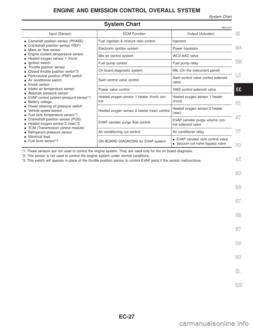
System ChartNBEC0013
Input (Sensor) ECM Function Output (Actuator)
ICamshaft position sensor (PHASE)
ICrankshaft position sensor (REF)
IMass air flow sensor
IEngine coolant temperature sensor
IHeated oxygen sensor 1 (front)
IIgnition switch
IThrottle position sensor
IClosed throttle position switch*3
IPark/neutral position (PNP) switch
IAir conditioner switch
IKnock sensor
IIntake air temperature sensor
IAbsolute pressure sensor
IEVAP control system pressure sensor*1
IBattery voltage
IPower steering oil pressure switch
IVehicle speed sensor
IFuel tank temperature sensor*1
ICrankshaft position sensor (POS)
IHeated oxygen sensor 2 (rear)*2
ITCM (Transmission control module)
IRefrigerant pressure sensor
IElectrical load
IFuel level sensor*1Fuel injection & mixture ratio control Injectors
Electronic ignition system Power transistor
Idle air control system IACV-AAC valve
Fuel pump control Fuel pump relay
On board diagnostic system MIL (On the instrument panel)
Swirl control valve controlSwirl control valve control solenoid
valve
Power valve control VIAS control solenoid valve
Heated oxygen sensor 1 heater (front) con-
trolHeated oxygen sensor 1 heater
(front)
Heated oxygen sensor 2 heater (rear) controlHeated oxygen sensor 2 heater
(rear)
EVAP canister purge flow controlEVAP canister purge volume con-
trol solenoid valve
Air conditioning cut control Air conditioner relay
ON BOARD DIAGNOSIS for EVAP systemIEVAP canister vent control valve
IVacuum cut valve bypass valve
*1: These sensors are not used to control the engine system. They are used only for the on board diagnosis.
*2: This sensor is not used to control the engine system under normal conditions.
*3: This switch will operate in place of the throttle position sensor to control EVAP parts if the sensor malfunctions.GI
MA
EM
LC
FE
AT
TF
PD
AX
SU
BR
ST
RS
BT
HA
SC
EL
IDX
ENGINE AND EMISSION CONTROL OVERALL SYSTEM
System Chart
EC-27
Page 563 of 2395
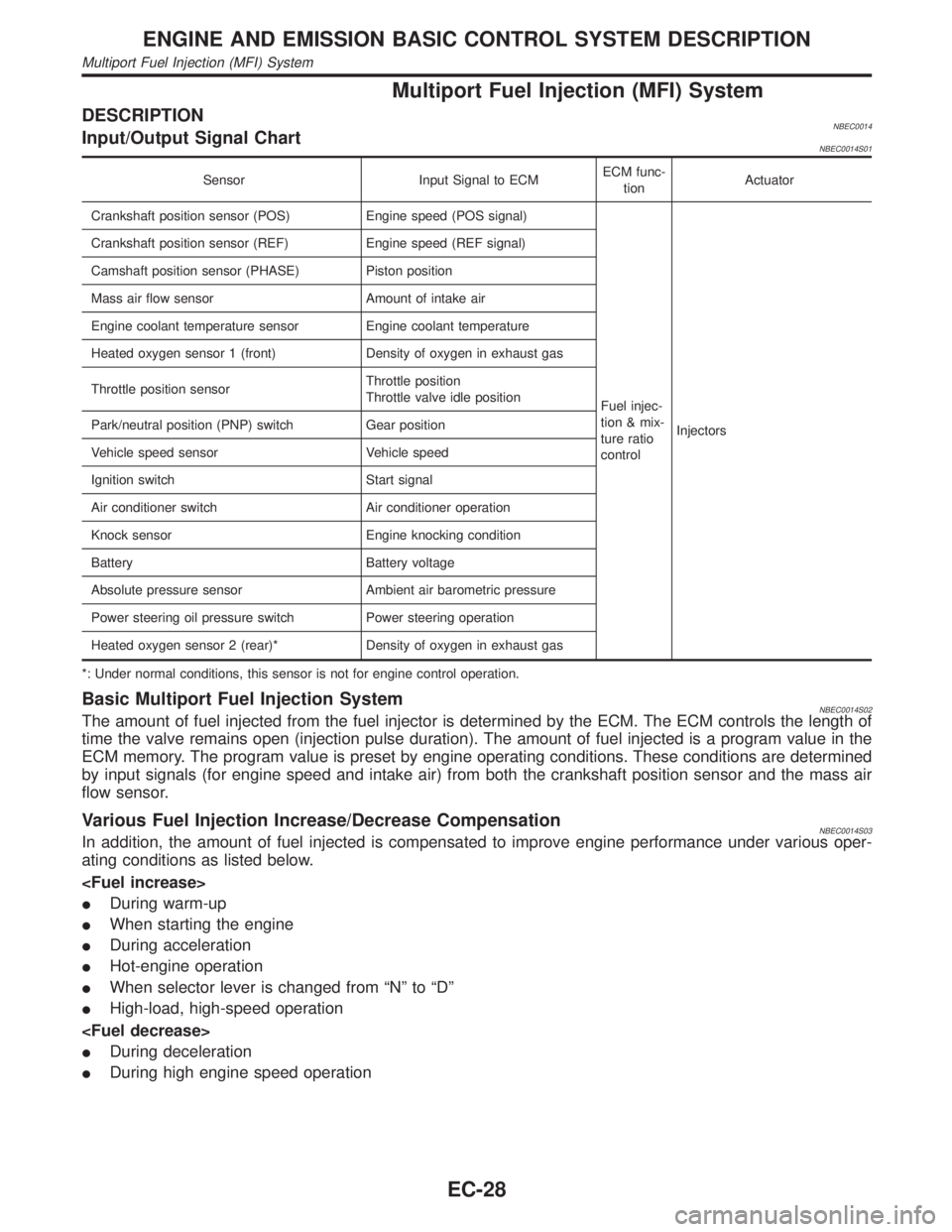
Multiport Fuel Injection (MFI) System
DESCRIPTIONNBEC0014Input/Output Signal ChartNBEC0014S01
Sensor Input Signal to ECMECM func-
tionActuator
Crankshaft position sensor (POS) Engine speed (POS signal)
Fuel injec-
tion & mix-
ture ratio
controlInjectors Crankshaft position sensor (REF) Engine speed (REF signal)
Camshaft position sensor (PHASE) Piston position
Mass air flow sensor Amount of intake air
Engine coolant temperature sensor Engine coolant temperature
Heated oxygen sensor 1 (front) Density of oxygen in exhaust gas
Throttle position sensorThrottle position
Throttle valve idle position
Park/neutral position (PNP) switch Gear position
Vehicle speed sensor Vehicle speed
Ignition switch Start signal
Air conditioner switch Air conditioner operation
Knock sensor Engine knocking condition
Battery Battery voltage
Absolute pressure sensor Ambient air barometric pressure
Power steering oil pressure switch Power steering operation
Heated oxygen sensor 2 (rear)* Density of oxygen in exhaust gas
*: Under normal conditions, this sensor is not for engine control operation.
Basic Multiport Fuel Injection SystemNBEC0014S02The amount of fuel injected from the fuel injector is determined by the ECM. The ECM controls the length of
time the valve remains open (injection pulse duration). The amount of fuel injected is a program value in the
ECM memory. The program value is preset by engine operating conditions. These conditions are determined
by input signals (for engine speed and intake air) from both the crankshaft position sensor and the mass air
flow sensor.
Various Fuel Injection Increase/Decrease CompensationNBEC0014S03In addition, the amount of fuel injected is compensated to improve engine performance under various oper-
ating conditions as listed below.
IDuring warm-up
IWhen starting the engine
IDuring acceleration
IHot-engine operation
IWhen selector lever is changed from ªNº to ªDº
IHigh-load, high-speed operation
IDuring deceleration
IDuring high engine speed operation
ENGINE AND EMISSION BASIC CONTROL SYSTEM DESCRIPTION
Multiport Fuel Injection (MFI) System
EC-28
Page 565 of 2395
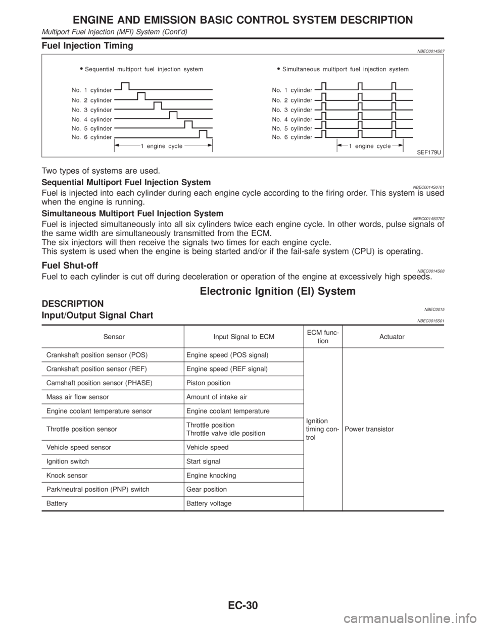
Fuel Injection TimingNBEC0014S07
SEF179U
Two types of systems are used.
Sequential Multiport Fuel Injection System
NBEC0014S0701Fuel is injected into each cylinder during each engine cycle according to the firing order. This system is used
when the engine is running.
Simultaneous Multiport Fuel Injection System
NBEC0014S0702Fuel is injected simultaneously into all six cylinders twice each engine cycle. In other words, pulse signals of
the same width are simultaneously transmitted from the ECM.
The six injectors will then receive the signals two times for each engine cycle.
This system is used when the engine is being started and/or if the fail-safe system (CPU) is operating.
Fuel Shut-offNBEC0014S08Fuel to each cylinder is cut off during deceleration or operation of the engine at excessively high speeds.
Electronic Ignition (EI) System
DESCRIPTIONNBEC0015Input/Output Signal ChartNBEC0015S01
Sensor Input Signal to ECMECM func-
tionActuator
Crankshaft position sensor (POS) Engine speed (POS signal)
Ignition
timing con-
trolPower transistor Crankshaft position sensor (REF) Engine speed (REF signal)
Camshaft position sensor (PHASE) Piston position
Mass air flow sensor Amount of intake air
Engine coolant temperature sensor Engine coolant temperature
Throttle position sensorThrottle position
Throttle valve idle position
Vehicle speed sensor Vehicle speed
Ignition switch Start signal
Knock sensor Engine knocking
Park/neutral position (PNP) switch Gear position
Battery Battery voltage
ENGINE AND EMISSION BASIC CONTROL SYSTEM DESCRIPTION
Multiport Fuel Injection (MFI) System (Cont'd)
EC-30