oil level INFINITI QX4 2001 Factory Service Manual
[x] Cancel search | Manufacturer: INFINITI, Model Year: 2001, Model line: QX4, Model: INFINITI QX4 2001Pages: 2395, PDF Size: 43.2 MB
Page 36 of 2395
SAT015J
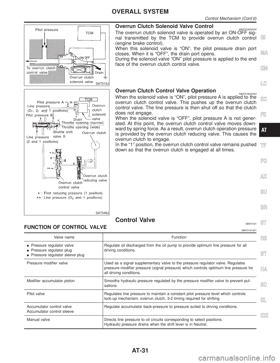
Overrun Clutch Solenoid Valve ControlNBAT0180S0402The overrun clutch solenoid valve is operated by an ON-OFF sig-
nal transmitted by the TCM to provide overrun clutch control
(engine brake control).
When this solenoid valve is ªONº, the pilot pressure drain port
closes. When it is ªOFFº, the drain port opens.
During the solenoid valve ªONº pilot pressure is applied to the end
face of the overrun clutch control valve.
SAT049J
Overrun Clutch Control Valve OperationNBAT0180S0403When the solenoid valve is ªONº, pilot pressure A is applied to the
overrun clutch control valve. This pushes up the overrun clutch
control valve. The line pressure is then shut off so that the clutch
does not engage.
When the solenoid valve is ªOFFº, pilot pressure A is not gener-
ated. At this point, the overrun clutch control valve moves down-
ward by spring force. As a result, overrun clutch operation pressure
is provided by the overrun clutch reducing valve. This causes the
overrun clutch to engage.
In the ª1º position, the overrun clutch control valve remains pushed
down so that the overrun clutch is engaged at all times.
Control ValveNBAT0181FUNCTION OF CONTROL VALVENBAT0181S01
Valve name Function
IPressure regulator valve
IPressure regulator plug
IPressure regulator sleeve plugRegulate oil discharged from the oil pump to provide optimum line pressure for all
driving conditions.
Pressure modifier valve Used as a signal supplementary valve to the pressure regulator valve. Regulates
pressure-modifier pressure (signal pressure) which controls optimum line pressure for
all driving conditions.
Modifier accumulator piston Smooths hydraulic pressure regulated by the pressure modifier valve to prevent pul-
sations.
Pilot valve Regulates line pressure to maintain a constant pilot pressure level which controls
lock-up mechanism, overrun clutch, 3-2 timing required for shifting.
Accumulator control valve
Accumulator control sleeveRegulate accumulator back-pressure to pressure suited to driving conditions.
Manual valve Directs line pressure to oil circuits corresponding to select positions.
Hydraulic pressure drains when the shift lever is in Neutral.
GI
MA
EM
LC
EC
FE
TF
PD
AX
SU
BR
ST
RS
BT
HA
SC
EL
IDX
OVERALL SYSTEM
Control Mechanism (Cont'd)
AT-31
Page 64 of 2395
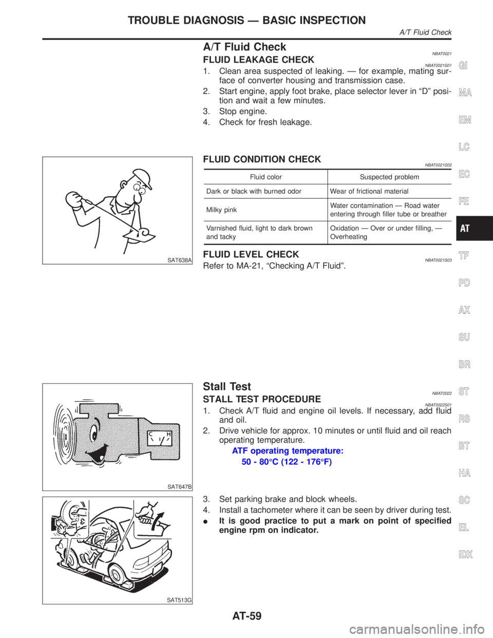
A/T Fluid CheckNBAT0021FLUID LEAKAGE CHECKNBAT0021S011. Clean area suspected of leaking. Ð for example, mating sur-
face of converter housing and transmission case.
2. Start engine, apply foot brake, place selector lever in ªDº posi-
tion and wait a few minutes.
3. Stop engine.
4. Check for fresh leakage.
SAT638A
FLUID CONDITION CHECKNBAT0021S02
Fluid color Suspected problem
Dark or black with burned odor Wear of frictional material
Milky pinkWater contamination Ð Road water
entering through filler tube or breather
Varnished fluid, light to dark brown
and tackyOxidation Ð Over or under filling, Ð
Overheating
FLUID LEVEL CHECKNBAT0021S03Refer to MA-21, ªChecking A/T Fluidº.
SAT647B
Stall TestNBAT0022STALL TEST PROCEDURENBAT0022S011. Check A/T fluid and engine oil levels. If necessary, add fluid
and oil.
2. Drive vehicle for approx. 10 minutes or until fluid and oil reach
operating temperature.
ATF operating temperature:
50 - 80ÉC (122 - 176ÉF)
SAT513G
3. Set parking brake and block wheels.
4. Install a tachometer where it can be seen by driver during test.
IIt is good practice to put a mark on point of specified
engine rpm on indicator.
GI
MA
EM
LC
EC
FE
TF
PD
AX
SU
BR
ST
RS
BT
HA
SC
EL
IDX
TROUBLE DIAGNOSIS Ð BASIC INSPECTION
A/T Fluid Check
AT-59
Page 67 of 2395

SAT209GA
Line Pressure TestNBAT0023ILocation of line pressure test ports.
IAlways replace line pressure plugs as they are self-seal-
ing bolts.
SAT647B
LINE PRESSURE TEST PROCEDURENBAT0023S011. Check A/T fluid and engine oil levels. If necessary, add fluid
and oil.
2. Drive vehicle for approx. 10 minutes or until fluid and oil reach
operating temperature.
ATF operating temperature:
50 - 80ÉC (122 - 176ÉF)
SAT518GB
SAT519GB
3. Install pressure gauge to corresponding line pressure port.
SAT513G
4. Set parking brake and block wheels.
IContinue to depress brake pedal fully while line pressure
test is being performed at stall speed.
TROUBLE DIAGNOSIS Ð BASIC INSPECTION
Line Pressure Test
AT-62
Page 91 of 2395

Items Symptom Condition Diagnostic Item Reference Page
Slips/Will Not
EngageVehicle will not
run in D, 1, 2
positions (but
runs in R posi-
tion). Clutch slips.
Very poor accel-
eration.
AT-230ON vehicle1. Fluid level AT-59
2. Line pressure test AT-62
3. Line pressure solenoid valve AT-162
4. Control valve assembly AT-273
5. Accumulator N-D AT-273
OFF vehicle6. Reverse clutch AT-314
7. High clutch AT-317
8. Forward clutch AT-320
9. Forward one-way clutch AT-330
10. Low one-way clutch AT-328
Clutches or
brakes slip some-
what in starting.ON vehicle1. Fluid level AT-59
2. Manual control linkage adjustment AT-276
3. Throttle position sensor (Adjustment) EC-174
4. Line pressure test AT-62
5. Line pressure solenoid valve AT-162
6. Control valve assembly AT-273
7. Accumulator N-D AT-273
OFF vehicle8. Forward clutch AT-320
9. Reverse clutch AT-314
10. Low & reverse brake AT-324
11. Oil pump AT-297
12. Torque converter AT-286
No creep at all.
AT-227, 230ON vehicle1. Fluid level AT-59
2. Line pressure test AT-62
3. Control valve assembly AT-273
OFF vehicle4. Forward clutch AT-320
5. Oil pump AT-297
6. Torque converter AT-286
Almost no shock
or clutches slip-
ping in change
from D
1to D2.ON vehicle1. Fluid level AT-59
2. Throttle position sensor (Adjustment) EC-174
3. Line pressure test AT-62
4. Accumulator servo release AT-273
5. Control valve assembly AT-273
OFF vehicle 6. Brake band AT-333
TROUBLE DIAGNOSIS Ð GENERAL DESCRIPTION
Symptom Chart (Cont'd)
AT-86
Page 93 of 2395

Items Symptom Condition Diagnostic Item Reference Page
Slips/Will Not
EngageRaces extremely
fast or slips in
changing from D
4or D3to D1when
depressing pedal.ON vehicle1. Fluid level AT-59
2. Throttle position sensor (Adjustment) EC-174
3. Line pressure test AT-62
4. Line pressure solenoid valve AT-162
5. Control valve assembly AT-273
OFF vehicle6. Forward clutch AT-320
7. Forward one-way clutch AT-330
8. Low one-way clutch AT-328
Vehicle will not
run in any posi-
tion.ON vehicle1. Fluid level AT-59
2. Manual control linkage adjustment AT-276
3. Line pressure test AT-62
4. Line pressure solenoid valve AT-162
OFF vehicle5. Oil pump AT-297
6. High clutch AT-317
7. Brake band AT-333
8. Low & reverse brake AT-324
9. Torque converter AT-286
10. Parking pawl components AT-337
NOT USEDEngine cannot be
started in P and N
positions.
AT-221ON vehicle1. Ignition switch and starter EL-9, and SC-10
2. Manual control linkage adjustment AT-276
3. Park/neutral position (PNP) switch
adjustmentAT-276
Engine starts in
positions other
than P and N.
AT-221ON vehicle1. Manual control linkage adjustment AT-276
2. Park/neutral position (PNP) switch
adjustmentAT-276
Transmission
noise in P and N
positions.ON vehicle1. Fluid level AT-59
2. Line pressure test AT-62
3. Throttle position sensor (Adjustment) EC-174
4. Vehicle speed sensor´A/T (Revolution
sensor) and vehicle speed sensor´MTRAT- 111 , 1 9 7
5. Engine speed signal AT-116
OFF vehicle6. Oil pump AT-297
7. Torque converter AT-286
Vehicle moves
when changing
into P position or
parking gear does
not disengage
when shifted out
of P position.
AT-222ON vehicle 1. Manual control linkage adjustment AT-276
OFF vehicle 2. Parking pawl components AT-337
TROUBLE DIAGNOSIS Ð GENERAL DESCRIPTION
Symptom Chart (Cont'd)
AT-88
Page 95 of 2395

Items Symptom Condition Diagnostic Item Reference Page
NOT USEDMaximum speed
not attained.
Acceleration poor.ON vehicle1. Fluid level AT-59
2. Park/neutral position (PNP) switch
adjustmentAT-276
3. Shift solenoid valve A AT-168
4. Shift solenoid valve B AT-172
5. Control valve assembly AT-273
OFF vehicle6. Reverse clutch AT-314
7. High clutch AT-317
8. Brake band AT-333
9. Low & reverse brake AT-324
10. Oil pump AT-297
11. Torque converter AT-286
Transmission
noise in D, 2, 1
and R positions.ON vehicle 1. Fluid level AT-59
ON vehicle 2. Torque converter AT-286
Engine brake
does not operate
in ª1º position.
AT-252ON vehicle1. Park/neutral position (PNP) switch
adjustmentAT-276
2. Manual control linkage adjustment AT-276
3. Throttle position sensor (Adjustment) EC-174
4. Vehicle speed sensor´A/T (Revolution
sensor) and vehicle speed sensor´MTRAT- 111 , 1 9 7
5. Shift solenoid valve A AT-168
6. Control valve assembly AT-273
7. Overrun clutch solenoid valve AT-185
OFF vehicle8. Overrun clutch AT-320
9. Low & reverse brake AT-324
Transmission
overheats.ON vehicle1. Fluid level AT-59
2. Engine idling rpm EC-431
3. Throttle position sensor (Adjustment) EC-174
4. Line pressure test AT-62
5. Line pressure solenoid valve AT-162
6. Control valve assembly AT-273
OFF vehicle7. Oil pump AT-297
8. Reverse clutch AT-314
9. High clutch AT-317
10. Brake band AT-333
11. Forward clutch AT-320
12. Overrun clutch AT-320
13. Low & reverse brake AT-324
14. Torque converter AT-286
TROUBLE DIAGNOSIS Ð GENERAL DESCRIPTION
Symptom Chart (Cont'd)
AT-90
Page 96 of 2395
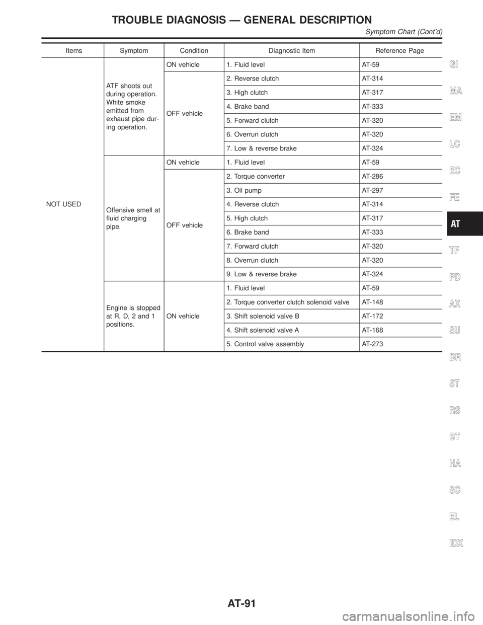
Items Symptom Condition Diagnostic Item Reference Page
NOT USEDATF shoots out
during operation.
White smoke
emitted from
exhaust pipe dur-
ing operation.ON vehicle 1. Fluid level AT-59
OFF vehicle2. Reverse clutch AT-314
3. High clutch AT-317
4. Brake band AT-333
5. Forward clutch AT-320
6. Overrun clutch AT-320
7. Low & reverse brake AT-324
Offensive smell at
fluid charging
pipe.ON vehicle 1. Fluid level AT-59
OFF vehicle2. Torque converter AT-286
3. Oil pump AT-297
4. Reverse clutch AT-314
5. High clutch AT-317
6. Brake band AT-333
7. Forward clutch AT-320
8. Overrun clutch AT-320
9. Low & reverse brake AT-324
Engine is stopped
at R, D, 2 and 1
positions.ON vehicle1. Fluid level AT-59
2. Torque converter clutch solenoid valve AT-148
3. Shift solenoid valve B AT-172
4. Shift solenoid valve A AT-168
5. Control valve assembly AT-273
GI
MA
EM
LC
EC
FE
TF
PD
AX
SU
BR
ST
RS
BT
HA
SC
EL
IDX
TROUBLE DIAGNOSIS Ð GENERAL DESCRIPTION
Symptom Chart (Cont'd)
AT-91
Page 229 of 2395
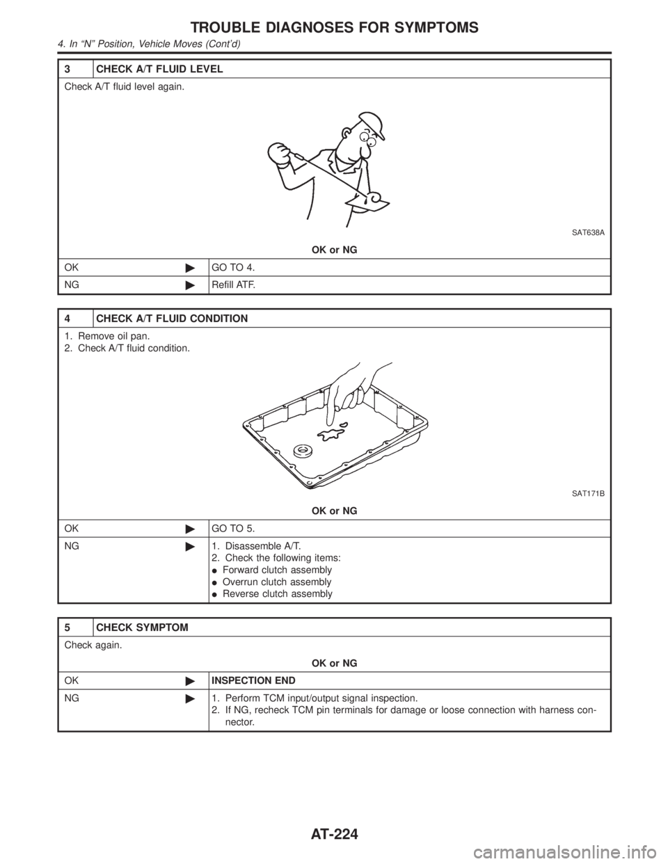
3 CHECK A/T FLUID LEVEL
Check A/T fluid level again.
SAT638A
OK or NG
OK©GO TO 4.
NG©Refill ATF.
4 CHECK A/T FLUID CONDITION
1. Remove oil pan.
2. Check A/T fluid condition.
SAT171B
OK or NG
OK©GO TO 5.
NG©1. Disassemble A/T.
2. Check the following items:
IForward clutch assembly
IOverrun clutch assembly
IReverse clutch assembly
5 CHECK SYMPTOM
Check again.
OK or NG
OK©INSPECTION END
NG©1. Perform TCM input/output signal inspection.
2. If NG, recheck TCM pin terminals for damage or loose connection with harness con-
nector.
TROUBLE DIAGNOSES FOR SYMPTOMS
4. In ªNº Position, Vehicle Moves (Cont'd)
AT-224
Page 232 of 2395

6. Vehicle Does Not Creep Backward In ªRº
Position
=NBAT0078SYMPTOM:
Vehicle does not creep backward when selecting ªRº position.
1 CHECK A/T FLUID LEVEL
Check A/T fluid level again.
SAT638A
OK or NG
OK©GO TO 2.
NG©Refill ATF.
2 CHECK STALL TEST
Check stall revolution with selector lever in ª1º and ªRº positions.
Refer to AT-356.
SAT493G
OK or NG
OK©GO TO 3.
OK in ª1º position, NG in
ªRº position©1. Remove control valve assembly. Refer to ªON-VEHICLE SERVICEº, AT-273.
2. Check the following items:
IValves to control line pressure (Pressure regulator valve, pressure modifier valve, pilot
valve and pilot filter)
ILine pressure solenoid valve
3. Disassemble A/T.
4. Check the following items:
IOil pump assembly
ITorque converter
IReverse clutch assembly
IHigh clutch assembly
NG in both ª1º and ªRº
positions©GO TO 6.
GI
MA
EM
LC
EC
FE
TF
PD
AX
SU
BR
ST
RS
BT
HA
SC
EL
IDX
TROUBLE DIAGNOSES FOR SYMPTOMS
6. Vehicle Does Not Creep Backward In ªRº Position
AT-227
Page 396 of 2395
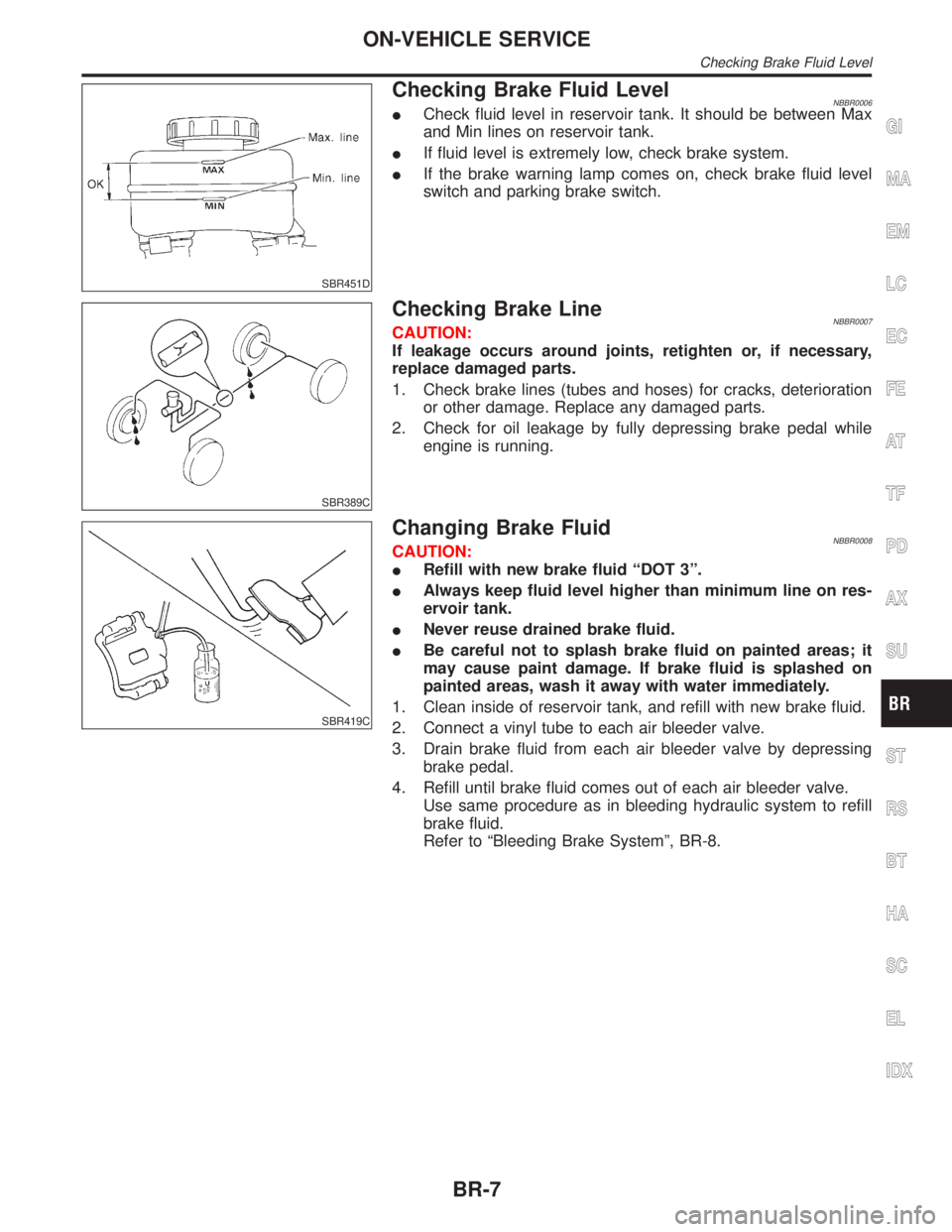
SBR451D
Checking Brake Fluid LevelNBBR0006ICheck fluid level in reservoir tank. It should be between Max
and Min lines on reservoir tank.
IIf fluid level is extremely low, check brake system.
IIf the brake warning lamp comes on, check brake fluid level
switch and parking brake switch.
SBR389C
Checking Brake LineNBBR0007CAUTION:
If leakage occurs around joints, retighten or, if necessary,
replace damaged parts.
1. Check brake lines (tubes and hoses) for cracks, deterioration
or other damage. Replace any damaged parts.
2. Check for oil leakage by fully depressing brake pedal while
engine is running.
SBR419C
Changing Brake FluidNBBR0008CAUTION:
IRefill with new brake fluid ªDOT 3º.
IAlways keep fluid level higher than minimum line on res-
ervoir tank.
INever reuse drained brake fluid.
IBe careful not to splash brake fluid on painted areas; it
may cause paint damage. If brake fluid is splashed on
painted areas, wash it away with water immediately.
1. Clean inside of reservoir tank, and refill with new brake fluid.
2. Connect a vinyl tube to each air bleeder valve.
3. Drain brake fluid from each air bleeder valve by depressing
brake pedal.
4. Refill until brake fluid comes out of each air bleeder valve.
Use same procedure as in bleeding hydraulic system to refill
brake fluid.
Refer to ªBleeding Brake Systemº, BR-8.
GI
MA
EM
LC
EC
FE
AT
TF
PD
AX
SU
ST
RS
BT
HA
SC
EL
IDX
ON-VEHICLE SERVICE
Checking Brake Fluid Level
BR-7