Wiring harness ISUZU KB P190 2007 Workshop Owners Manual
[x] Cancel search | Manufacturer: ISUZU, Model Year: 2007, Model line: KB P190, Model: ISUZU KB P190 2007Pages: 6020, PDF Size: 70.23 MB
Page 3128 of 6020

Engine Mechanical – V6 Page 6A1–351
Page 6A1–351
6 Torque Wrench Specifications
ATTENTION
�„ Fasteners must be replaced after loosening.
Fasteners either have micro encapsulated sealant a pplied or incorporate a mechanical thread lock and
should only be re-used once. If in doubt, replacement is recommended.
Oil Pan Drain Plug ................................................................................ 25.0 Nm
Oil Filter Adaptor Attach ing Bolt................................................ 20.0 – 26.0 Nm
Oil Level Indicator Tube Atta ching Bolt........................................ 8.0 – 12.0 Nm
Accessory Drive Belt Idler Pu lley Attaching Bolt................................... 50.0 Nm
Accessory Drive Belt Tensio ner Attaching Bolt .................................... 50.0 Nm
Power Steering Reserv oir Bracket Attaching Screw.............................. 9.0 Nm
Power Steering Pump Bracket A ttaching Bolt ........................... 49. 0 – 67.0 Nm
Upper Intake Manifold to Lower Intake Manifold Attaching Bolt ........... 23.0 Nm
Upper Intake Manifold to Cylinder Head Attaching Bolt........................ 23.0 Nm
Lower Intake Manifold to Cylind er Head Attaching Bolt........................ 23.0 Nm
Fuel Injector Wiring Harness Br acket Attaching bolt .............................. 9. 0 Nm
Exhaust Manifold to Cylinder He ad Attaching Bolt..................... 17.0 - 23.0 Nm
Exhaust Manifold Heat Shield Attaching Bolt ............................... 8.0 - 12.0 Nm
Battery Harness Ground Terminal Attaching Nut ................................. 13. 0 Nm
Camshaft Cover Attachi ng Bolt................................................... 8.0 – 12.0 Nm
Engine Ground Connec tor Bolt............................................................. 10.0 Nm
Engine Wiring Harness Former A ttaching Bolt .......................... 12.0 – 16.0 Nm
�„ Crankshaft Balancer A ssembly Attaching Bolt:
Stage 1 ..................................................................................... 90.0 –110.0 Nm
Stage 2 ....................................................................................................... 150 °
Engine Front Cover Assembly A ttaching Bolt ............................ 20. 0 – 26.0 Nm
Camshaft Intermediate Sprocket Attaching Bolt ........................ 58. 0 – 72.0 Nm
Secondary Timing Chai n Guide Attaching Bolt.......................... 20.0 – 26.0 Nm
Secondary Timing Chai n Shoe Attaching Bolt ........................... 20.0 – 26.0 Nm
Secondary Timing Chain Tensioner Attachi ng Bolt ................... 20.0 – 26.0 Nm
Primary Timing Chain Upper Gui de Attaching Bolt.................... 20.0 – 26.0 Nm
Primary Timing Chain Tensioner Attaching Bolt........................ 20. 0 – 26.0 Nm
Oil Pump Assembly Attach ing Bolt............................................ 20.0 – 26.0 Nm
Camshaft Sprocket Attachi ng Bolt............................................. 49.0 – 67.0 Nm
Exhaust Camshaft Sprocket Atta ching Bolt............................... 49.0 – 67.0 Nm
Camshaft Bearing Cap Attach ing Bolt......................................... 8.0 – 12.0 Nm
Cylinder Head Thr eaded Plug.............................................................. 31.0 Nm
�„ Cylinder Head M11 Attaching Bolt:
Stage 1 ...................................................................................... 40.0 – 50.0 Nm
Stage 2 ....................................................................................................... 120 °
�„ Cylinder Head M8 Attaching Bolt:
Stage 1 ...................................................................................... 12.0 – 18.0 Nm
Stage 2 ......................................................................................................... 60 °
Engine Mount Bracket to Cylinder Bl ock Attaching Bolt............ 43.0 – 57.0 Nm
Engine Mount to Bracket Atta ching Nut..................................... 70.0 – 90.0 Nm
Engine Mount to Frame Atta ching Nut...................................... 44.0 – 60.0 Nm
Engine Lift Bracket Attachi ng Bolt.......................................... 58.0 – 72.0.0 Nm
Knock Sensor Attach ing Nut................................................................. 23.0 Nm
BACK TO CHAPTER INDEX
TO MODEL INDEX
ISUZU KB P190 2007
Page 3150 of 6020

Engine Cooling – V6 Engine Page 6B1–15
2.8 Engine Coolant Temperature Sensor
An Engine Coolant Temperature (ECT) sensor (2) is
mounted in the left-hand side cylinder head, just above
the exhaust manifold. The ECT sensor is used in
conjunction with the instrument panel temperature gauge.
The ECT sensor generates a signal, which is used by the
engine management system for calculation of the various
engine management functions.
Figure 6B1 – 13 shows the wiring harness connector (1)
and the ECT sensor (2).
Refer to 6C1-1 Engine Management General Information
for further information on the ECT sensor.
Figure 6B1 – 13
BACK TO CHAPTER INDEX
TO MODEL INDEX
ISUZU KB P190 2007
Page 3170 of 6020

Engine Cooling – V6 Engine Page 6B1–35
9 To gain easier access to the heater pipe flange and
thermostat housing bolts, disconnect the engine
harness and lay back on the right side of the engine
bay. Apart from those harness connectors removed
during the intake manifold removal, this involves the
removal of wiring harness connectors and fasteners,
as detailed:
a Pull out the release bar (arrows) on each of the ignition coil packs (1) on cylinders 2, 4 and 6,
before disconnecting each connector.
b The coolant temperature sensor.
c The left side Pre-O2 sensor connector, 2, 4 & 6.
NOTE
Refer to 8A – Electrical Body & Chassis for the
location of harness connectors, not shown.
Figure 6B1 –
––
–
34
10 Remove the bolt (1) securing the engine harness ground terminal (2), to the cylinder block.
11 Prise both locking legs of the left side engine harness former (4), free, then lift up on the harness former to
release.
Figure 6B1 –
––
–
35
12 W orking at the rear of the engine, disconnect the engine harness to transmission harness connector (1),
as required.
13 Remove the two bolts (2) securing the engine harness former (3) to the rear of the engine.
14 Carefully lift the engine harness free and drape on the right side of the engine.
NOTE
For further information on removing the
thermostat housing and associated components,
refer to 6A1 Engine Mechanical – V6.
Figure 6B1 –
––
–
36
BACK TO CHAPTER INDEX
TO MODEL INDEX
ISUZU KB P190 2007
Page 3173 of 6020

Engine Cooling – V6 Engine Page 6B1–38
Install
Always wear protective safety glasses when
working with spring-loaded devices. Failure to
do so could result in eye injury.
1 Install the thermostat into the housing (reverse to removal procedure).
2 Ensure that the engine block and thermostat housing mating surfaces are clean and dry.
3 Install a new gasket to the thermostat housing.
4 Install the thermostat housing to the engine block and secure with the attaching bolts (with rubber grommets installed). Tighten all bolts to the correct torque specification.
Thermostat housing to engine
block bolt torque specification ..............................10 N.m
5 Ensure that the heater pipe assembly and thermostat housing mating surfaces are clean and dry.
6 Install new O-rings to the heater pipe assembly.
7 Install heater pipe assembly to thermostat housing and secure with the attaching bolts. Tighten all bolts to the correct torque specification.
Heater pipe assembly to thermostat
housing bolt torque specification ..........................10 N.m
8 Install heater pipe assembly to right-hand cylinder head bolt. Tighten bolt to the correct torque specification. Heater pipe assembly to cylinder
head bolt torque specification ..............................35 N.m
Always wear protective safety glasses when
working with spring type hose clamps. Failure
to do so could result in eye injury.
9 Reinstall the engine wiring harness, securing the rear harness former to the rear of the engine with the two retaining bolts, tightened to the correct torque specification.
Rear engine harness former
retaining bolts torque specification .......................15 N.m
10 Reinstall the left side engine harness former to the two locating pegs, then push inward to secure.
11 Reinstall the bolt securing the engine harness ground terminal, to the left side of the cylinder block and tighten to the correct torque specification.
Engine harness ground terminal
attaching bolt torque specification ........................12 N.m
12 Reinstall each wiring harness connector to its correct location, ensuring that all security clips are installed correctly.
13 Connect the heater hoses to the heater pipe assembly.
14 Install the coolant inlet pipe. Refer to 3.12 Coolant Inlet Pipe in this Section.
15 Close the radiator drain tap on the lower LHS of the radiator and remove the piece of rubber tubing to the tap outlet.
16 Reinstall the complete intake manifold assembly. Refer to 6A1 Engine Mechanical.
17 Refill cooling system. Refer to 3.3 Draining and Filling Cooling System in this Section.
BACK TO CHAPTER INDEX
TO MODEL INDEX
ISUZU KB P190 2007
Page 3184 of 6020
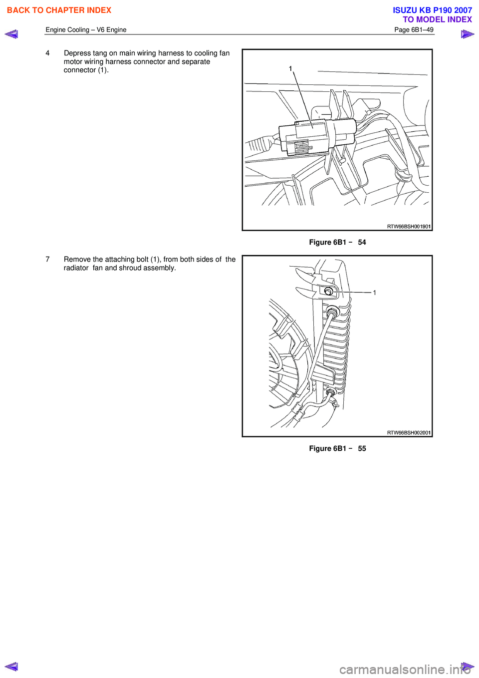
Engine Cooling – V6 Engine Page 6B1–49
4 Depress tang on main wiring harness to cooling fan
motor wiring harness connector and separate
connector (1).
Figure 6B1 –
––
–
54
7 Remove the attaching bolt (1), from both sides of the radiator fan and shroud assembly.
Figure 6B1 –
––
–
55
BACK TO CHAPTER INDEX
TO MODEL INDEX
ISUZU KB P190 2007
Page 3186 of 6020
Engine Cooling – V6 Engine Page 6B1–51
Disassemble
1 Remove cooling fan and shroud assembly as previously described.
NOTE
Neither fan is to be separated from its fan motor.
The assembly is carefully balanced during
manufacture and duplicating this balance on
reassembly, is not possible.
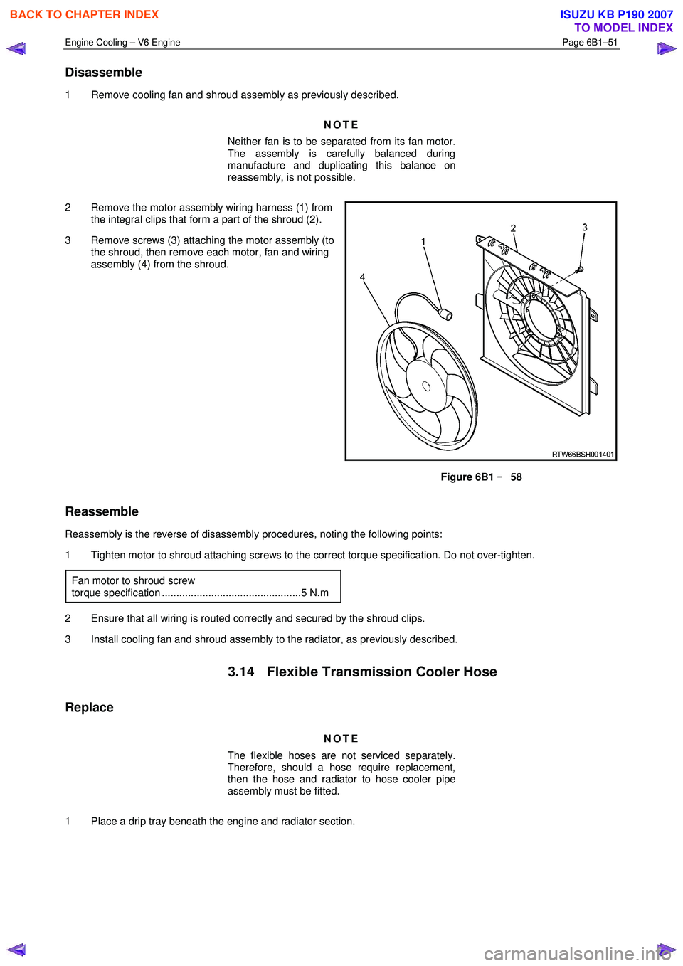
2 Remove the motor assembly wiring harness (1) from the integral clips that form a part of the shroud (2).
3 Remove screws (3) attaching the motor assembly (to the shroud, then remove each motor, fan and wiring
assembly (4) from the shroud.
Figure 6B1 –
––
–
58
Reassemble
Reassembly is the reverse of disassembly procedures, noting the following points:
1 Tighten motor to shroud attaching screws to the correct torque specification. Do not over-tighten.
Fan motor to shroud screw
torque specification ................................................5 N.m
2 Ensure that all wiring is routed correctly and secured by the shroud clips.
3 Install cooling fan and shroud assembly to the radiator, as previously described.
3.14 Flexible Transmission Cooler Hose
Replace
NOTE
The flexible hoses are not serviced separately.
Therefore, should a hose require replacement,
then the hose and radiator to hose cooler pipe
assembly must be fitted.
1 Place a drip tray beneath the engine and radiator section.
BACK TO CHAPTER INDEX
TO MODEL INDEX
ISUZU KB P190 2007
Page 3189 of 6020
Engine Cooling – V6 Engine Page 6B1–54
3.15 Radiator
Remove
Refer to 3.1 Service Notes in this Section, for
important safety items.
1 Allow engine to cool to ambient temperature (less than 50 ° C), then remove coolant filler cap.
Disconnection of the battery affects certain
vehicle electronic systems. Refer to 00
Warnings, Cautions and Notes, before
removing the ground lead.
2 Disconnect the battery ground lead. Refer to 8A – Electrical Body & Chassis.
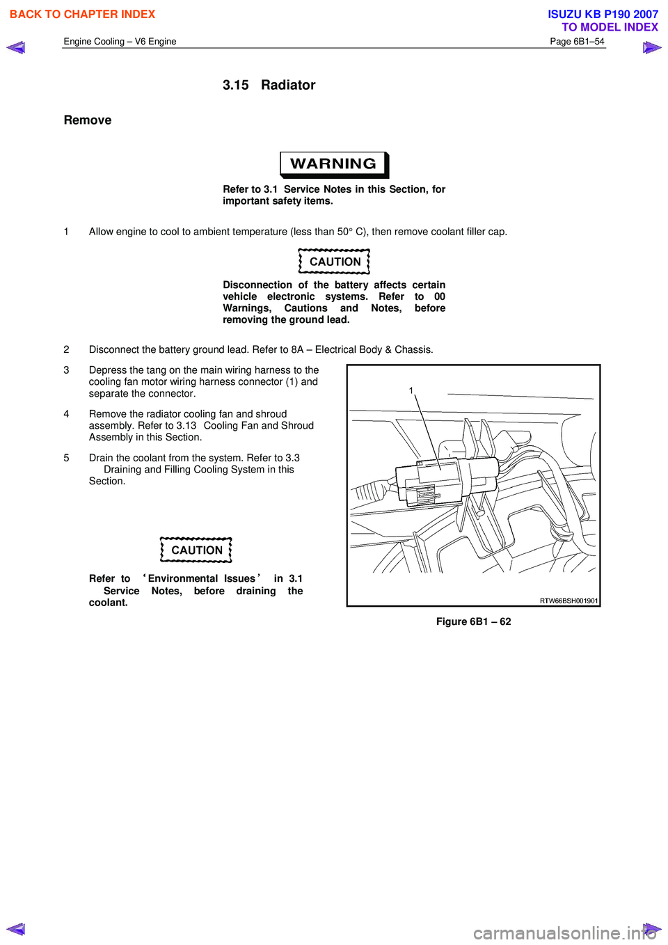
3 Depress the tang on the main wiring harness to the cooling fan motor wiring harness connector (1) and
separate the connector.
4 Remove the radiator cooling fan and shroud assembly. Refer to 3.13 Cooling Fan and Shroud
Assembly in this Section.
5 Drain the coolant from the system. Refer to 3.3 Draining and Filling Cooling System in this
Section.
Refer to ‘
‘‘
‘
Environmental Issues ’
’’
’
in 3.1
Service Notes, before draining the
coolant.
Figure 6B1 – 62
BACK TO CHAPTER INDEX
TO MODEL INDEX
ISUZU KB P190 2007
Page 3269 of 6020
Engine Management – V6 – General Information Page 6C1-1–27
4.13 Fuel Rail Assembly
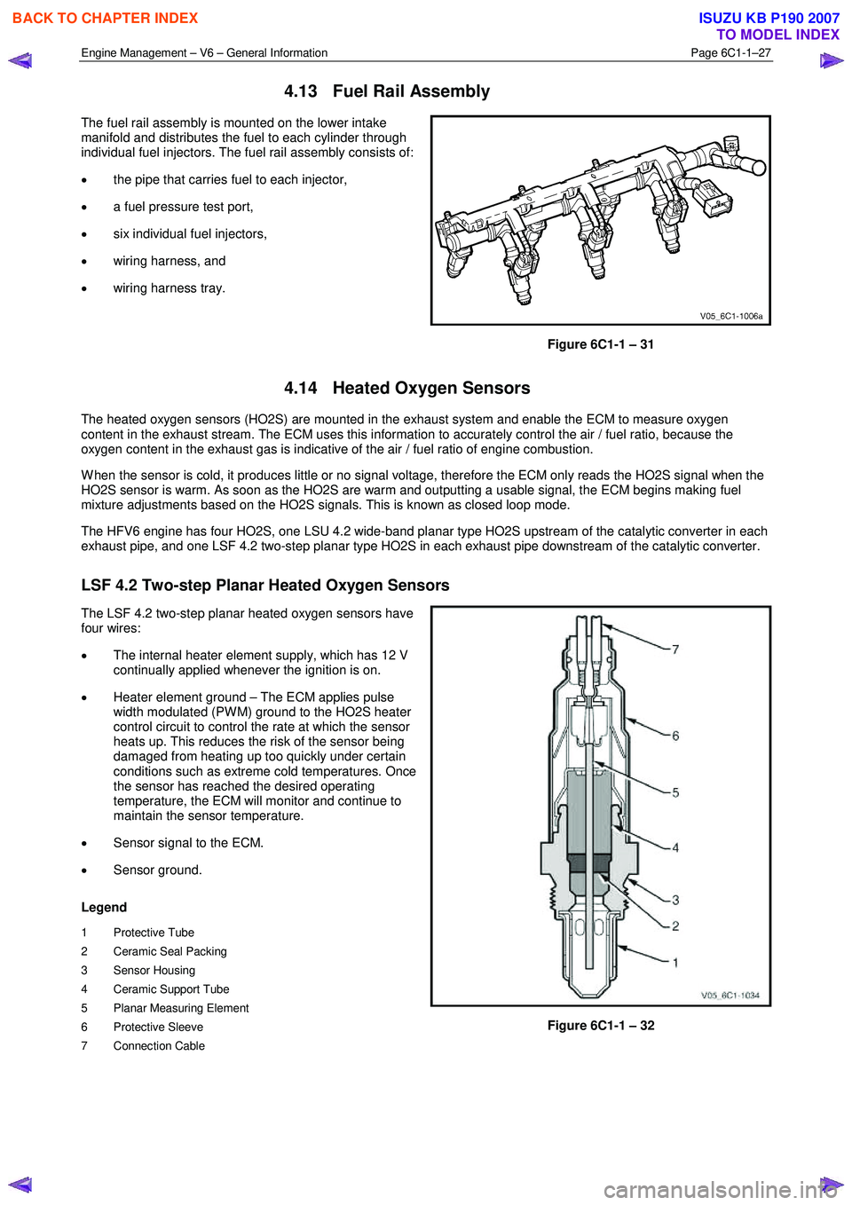
The fuel rail assembly is mounted on the lower intake
manifold and distributes the fuel to each cylinder through
individual fuel injectors. The fuel rail assembly consists of:
• the pipe that carries fuel to each injector,
• a fuel pressure test port,
• six individual fuel injectors,
• wiring harness, and
• wiring harness tray.
Figure 6C1-1 – 31
4.14 Heated Oxygen Sensors
The heated oxygen sensors (HO2S) are mounted in the exhaust system and enable the ECM to measure oxygen
content in the exhaust stream. The ECM uses this information to accurately control the air / fuel ratio, because the
oxygen content in the exhaust gas is indicative of the air / fuel ratio of engine combustion.
W hen the sensor is cold, it produces little or no signal voltage, therefore the ECM only reads the HO2S signal when the
HO2S sensor is warm. As soon as the HO2S are warm and outputting a usable signal, the ECM begins making fuel
mixture adjustments based on the HO2S signals. This is known as closed loop mode.
The HFV6 engine has four HO2S, one LSU 4.2 wide-band planar type HO2S upstream of the catalytic converter in each
exhaust pipe, and one LSF 4.2 two-step planar type HO2S in each exhaust pipe downstream of the catalytic converter.
LSF 4.2 Two-step Planar Heated Oxygen Sensors
The LSF 4.2 two-step planar heated oxygen sensors have
four wires:
• The internal heater element supply, which has 12 V
continually applied whenever the ignition is on.
• Heater element ground – The ECM applies pulse
width modulated (PW M) ground to the HO2S heater
control circuit to control the rate at which the sensor
heats up. This reduces the risk of the sensor being
damaged from heating up too quickly under certain
conditions such as extreme cold temperatures. Once
the sensor has reached the desired operating
temperature, the ECM will monitor and continue to
maintain the sensor temperature.
• Sensor signal to the ECM.
• Sensor ground.
Legend
1 Protective Tube
2 Ceramic Seal Packing
3 Sensor Housing
4 Ceramic Support Tube
5 Planar Measuring Element
6 Protective Sleeve
7 Connection Cable
Figure 6C1-1 – 32
BACK TO CHAPTER INDEX
TO MODEL INDEX
ISUZU KB P190 2007
Page 3297 of 6020
Engine Management – V6 – Diagnostics Page 6C1-2–19
• Do not start the engine if the battery terminal is not properly secured to the battery.
• Do not disconnect or reconnect the following while the ignition is switched on or when the engine is running:
− Any engine management system component electrical wiring connector, or
− Battery terminal leads.
• Ensure the correct procedure for disconnecting and connecting engine management system electrical wiring
connectors is always followed. For information on the correct procedure for disconnecting and connecting specific
wiring connectors, refer to 6C1-3 Engine Management – V6 – Service Operations.
• Ensure that all wiring harness connectors are fitted correctly.
• W hen steam or pressure cleaning engines, do not direct the cleaning nozzle at engine management system
components.
• Do not clear any DTCs unless instructed.
• The fault must be present when using the diagnostic trouble code (DTC) diagnostic tables. Otherwise,
misdiagnosis or replacement of good parts may occur.
• Do not touch the ECM connector pins or soldered components on the ECM circuit board to prevent ECM
Electrostatic Discharge damage. Refer to 8A Electrical - Body and Chassis for information on Electrostatic
Discharge.
• Use only the test equipment specified in the diagnostic tables as other test equipment may give incorrect results or
damage good components.
• The ECM is designed to withstand normal current draw associated with vehicle operations. However, the following
fault conditions or incorrect test procedure may overload the ECM internal circuit and damage the ECM:
− A short to voltage fault condition in any of the ECM low reference circuits may cause internal ECM and / or
sensor damage. Therefore, any short to voltage fault condition in the ECM low reference circuits must be
rectified before replacing a faulty component.
− A short to ground fault condition in any of the ECM 5 V reference circuits may cause internal ECM and / or
sensor damage. Therefore, any short to ground fault condition in the ECM 5 V reference circuits must be
rectified before replacing a faulty component.
− W hen using a test lamp to test an electrical circuit, do not use any of the ECM low reference circuits or 5 V
reference circuits as a reference point. Otherwise, excessive current draw from the test lamp may damage
the ECM.
• Disregard DTCs that set while performing the following diagnostic Steps:
− Using Tech 2 actuator tests, or
− Disconnecting an engine management system sensor connector then switching on the ignition.
• After completing the required diagnostics and service operations, road test the vehicle to ensure correct engine
management system operation.
4.3 Preliminary Checks
The preliminary checks are a set of visual and physical checks or inspections that may quickly identify engine
management system fault condition.
• Refer to the appropriate Service Techlines for relevant information regarding the fault condition.
• Ensure the battery is fully charged.
• Inspect the battery connections for corrosion or a loose terminal.
• Ensure that all engine management system related fuses are serviceable.
• Inspect for incorrect aftermarket theft deterrent devices, lights or mobile phone installation.
• Ensure there is no speaker magnet positioned too close to any electronic module that contains relays.
• Inspect the engine wiring harness for proper connections, pinches or cuts.
• Ensure that all engine management related electrical wiring connectors are fitted correctly.
• Inspect the ECM ground connections for corrosion, loose terminal or incorrect position.
BACK TO CHAPTER INDEX
TO MODEL INDEX
ISUZU KB P190 2007
Page 3298 of 6020
Engine Management – V6 – Diagnostics Page 6C1-2–20
• Ensure the resistance between the ECM housing and the battery negative cable is less than 0.5 Ω.
• Check the ECM bracket fasteners for correct torque value.
• Check all engine management related components for correct installation.
• Inspect the vacuum hoses for splits, kinks, oil contamination and proper connections, refer to the vehicle emission
control information label. Check the hoses thoroughly for any type of leak or restriction.
• Inspect the air intake ducts for being collapsed, split or for having damaged areas.
• Inspect for air leaks at the throttle body mounting area, mass air flow (MAF) sensor, intake manifold and intake
manifold sealing surfaces.
• Check for wiring harness routing that may be positioned too close to a high voltage or high current device such as
the following:
− Secondary ignition components, and
− Motors and generators.
NOTE
High voltage or high current devices may induce
electrical noise on a circuit, which can interfere
with normal circuit operation.
4.4 Diagnostic System Check
Description
The engine management diagnostic procedure is organised in a logical structure that begins with the Diagnostic System
Check. The Diagnostic System Check directs the diagnostic procedure to the logical steps necessary to diagnose an
engine driveability fault condition.
Test Description
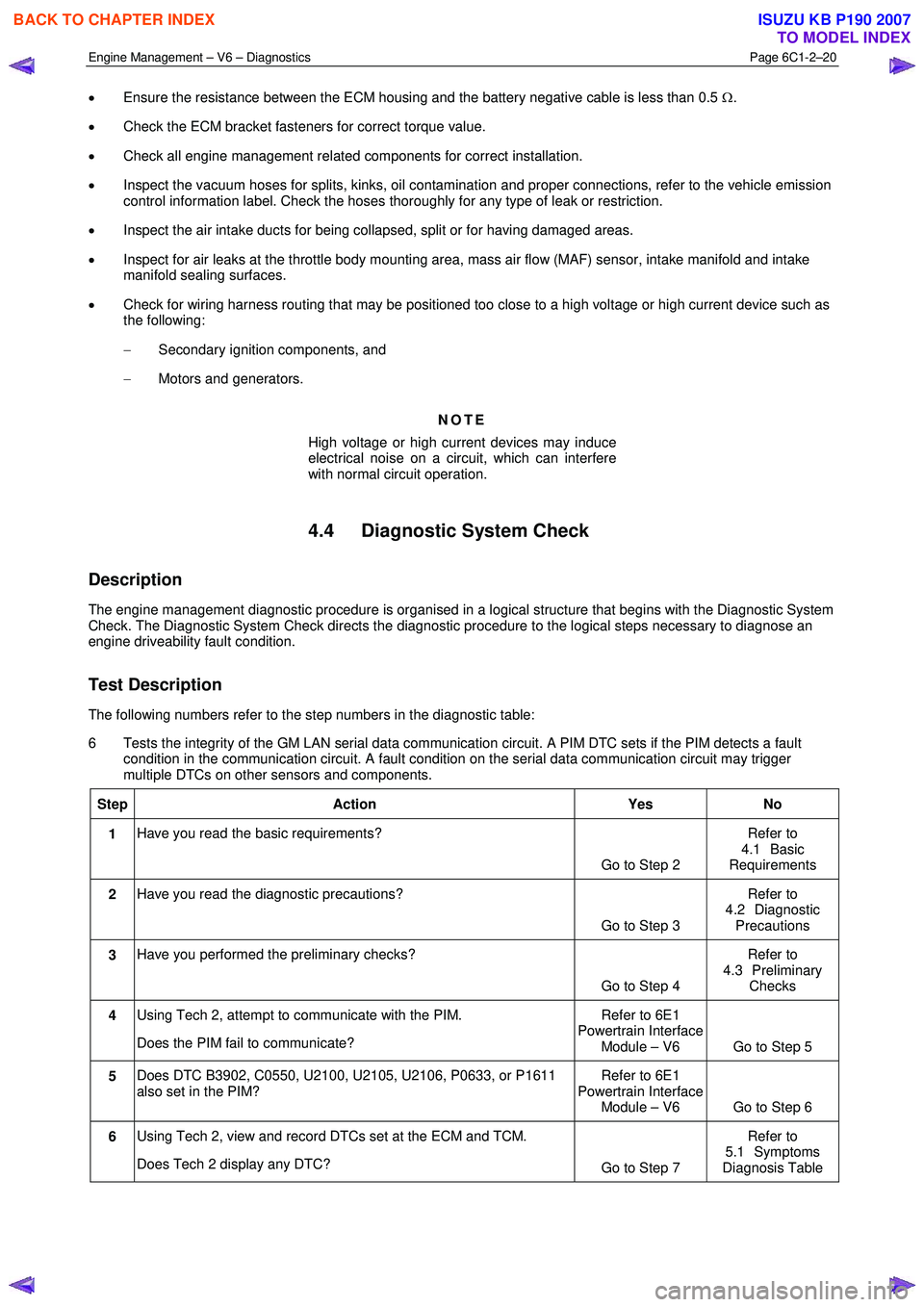
The following numbers refer to the step numbers in the diagnostic table:
6 Tests the integrity of the GM LAN serial data communication circuit. A PIM DTC sets if the PIM detects a fault condition in the communication circuit. A fault condition on the serial data communication circuit may trigger
multiple DTCs on other sensors and components.
Step Action Yes No
1 Have you read the basic requirements?
Go to Step 2 Refer to
4.1 Basic
Requirements
2 Have you read the diagnostic precautions?
Go to Step 3 Refer to
4.2 Diagnostic Precautions
3 Have you performed the preliminary checks?
Go to Step 4 Refer to
4.3 Preliminary Checks
4 Using Tech 2, attempt to communicate with the PIM.
Does the PIM fail to communicate? Refer to 6E1
Powertrain Interface Module – V6 Go to Step 5
5 Does DTC B3902, C0550, U2100, U2105, U2106, P0633, or P1611
also set in the PIM? Refer to 6E1
Powertrain Interface Module – V6 Go to Step 6
6 Using Tech 2, view and record DTCs set at the ECM and TCM.
Does Tech 2 display any DTC? Go to Step 7 Refer to
5.1 Symptoms
Diagnosis Table
BACK TO CHAPTER INDEX
TO MODEL INDEX
ISUZU KB P190 2007