Front suspension ISUZU KB P190 2007 Workshop Repair Manual
[x] Cancel search | Manufacturer: ISUZU, Model Year: 2007, Model line: KB P190, Model: ISUZU KB P190 2007Pages: 6020, PDF Size: 70.23 MB
Page 687 of 6020

5B-8 ANTI-LOCK BRAKE SYSTEM
Front Wheel Speed Sensor
Front Wheel Speed Sensor and Associated Parts
4×
××
×
2 (Except High Ride Suspension)
RTW 55ALF000401
Legend
(1) Connector Portion
(2) Front Speed Sensor Assembly
(3) Bolt: Cable to Knuckle
(4) Bolt: Sensor to Knuckle
(5) Nut: Cable to Upper Link
BACK TO CHAPTER INDEX
TO MODEL INDEX
ISUZU KB P190 2007
Page 688 of 6020

ANTI-LOCK BRAKE SYSTEM 5B-9
4×
××
×
2 High Ride Suspension, 4 ×
××
×
4
RTW 55ALF000201
Legend
(1) Connector Portion
(2) Front Speed Sensor Assembly
(3) Bolt: Cable to Knuckle
(4) Bolt: Sensor to Knuckle
(5) Bolt: Cable to Upper Link
Removal
1. Remove speed sensor connector at connector
portion.
2. Remove sensor fixing bolt (4).
3. Remove cable fixing bolts and nut (4 ×2).
4. Disconnect the arrow mark locks of the cable clips.
5. Remove the speed sensor assembly.
Inspection and Repair
1. Check the speed sensor head for presence of
foreign materials; remove any dirt, etc.
2. Check the head for damage; replace speed senso
r
if necessary.
3. Check the speed sensor cable for short or open circuit, and replace with a new one if necessary.
To check for cable short or open, bend or stretch the cable while checking for continuity.
BACK TO CHAPTER INDEX
TO MODEL INDEX
ISUZU KB P190 2007
Page 694 of 6020
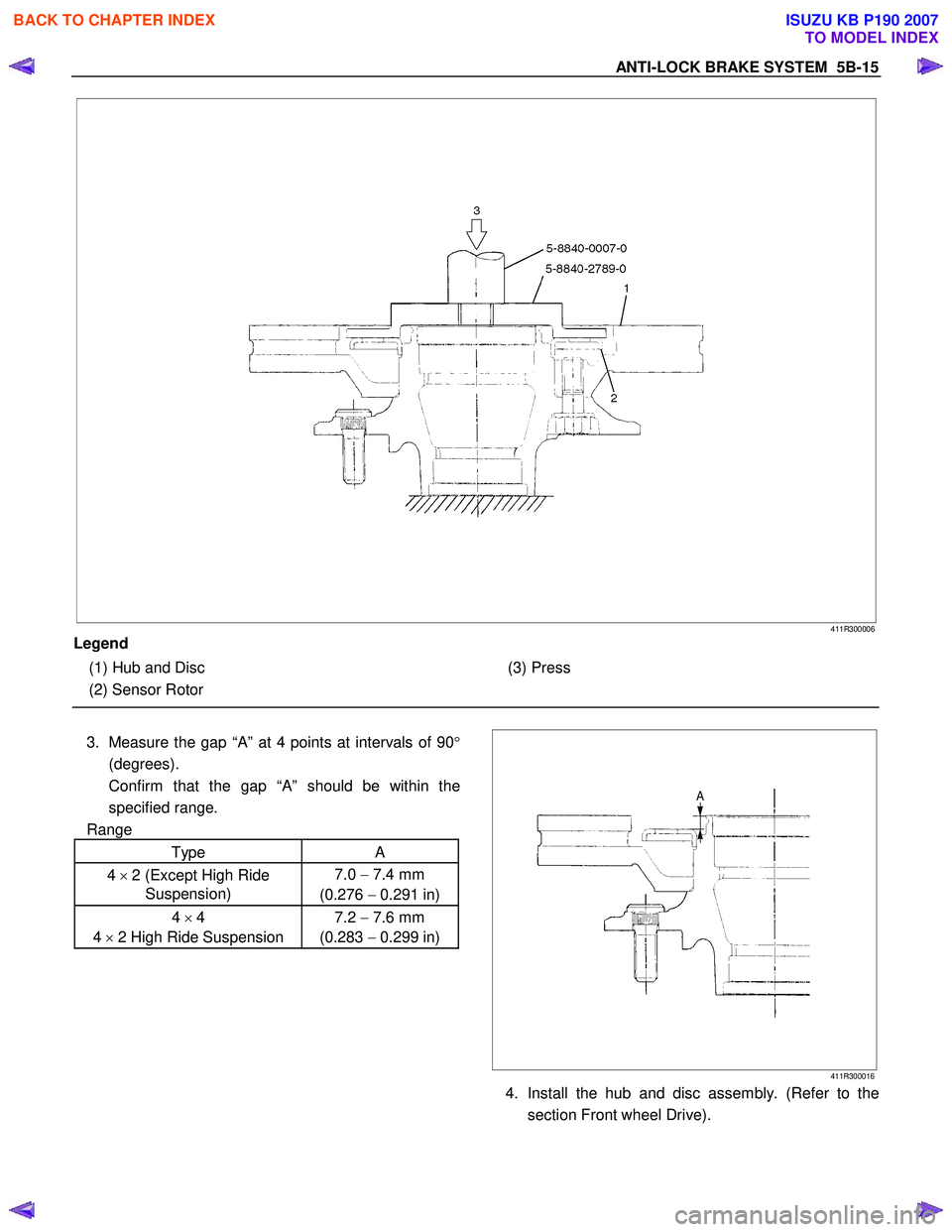
ANTI-LOCK BRAKE SYSTEM 5B-15
411R300006
Legend
(1) Hub and Disc
(2) Sensor Rotor
(3) Press
3. Measure the gap “A” at 4 points at intervals of 90 °
(degrees).
Confirm that the gap “A” should be within the
specified range.
Range
Type A
4 × 2 (Except High Ride
Suspension) 7.0
− 7.4 mm
(0.276 − 0.291 in)
4 × 4
4 × 2 High Ride Suspension 7.2
− 7.6 mm
(0.283 − 0.299 in)
411R300016
4. Install the hub and disc assembly. (Refer to the
section Front wheel Drive).
BACK TO CHAPTER INDEX
TO MODEL INDEX
ISUZU KB P190 2007
Page 721 of 6020

5C-22 BRAKES
RTW 35CSH001001
•
••
•
Operation
1) Outline
W hen the LSPV (Load Sensing Proportioning Valve) detects a change in load weight, the load sensing spring
stretches.
Its reaction force is transmitted to the bottom of the load sensing valve to secure an optimum rear wheel cylinde
r
fluid pressure break point in proportion to the actual load
weight.
Besides, if the front brake system should fail, the device is designed to prevent the master cylinder fluid pressure from
decreasing and to apply it directly to the rear wheel cylinde
r
to obtain a sufficient braking performance.
RTW 35CSH001101
2) Bellow cutting point.
The Force (F) keeps the main piston (1) the rest position. The inlet pressure (A) and outlet pressure (B) are the same
as well as the inlet pressure (C) from front master cylinder.
The bypass piston (2) is kept on rest position by equilibrium
of the pressures (A) and (C) and the bypass spring load (3).
RTW 35CSH001201
3) Cutting point.
The cutting point is given by relation between force (F), that is the load applied by suspension of the vehicle and the
main piston area (1). The cutting point is achieved when the
force generated by hydraulic pressure is upper than the
force (F) given by the load suspension. The main piston (1)
moves from the rest position closing the valve. In this
moment the inlet pressure (A) is upper than the outlet
pressure (B). The bypass piston (2) continues on the rest
position by equilibrium of (A) and (C) pressure.
BACK TO CHAPTER INDEX
TO MODEL INDEX
ISUZU KB P190 2007
Page 723 of 6020
5C-24 BRAKES
RTW 35CSH000201
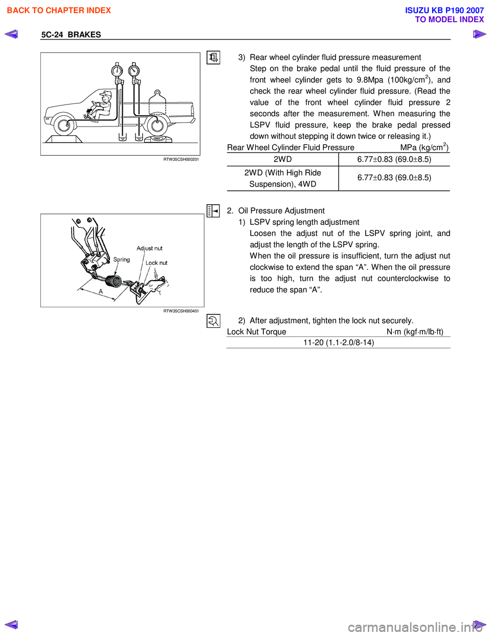
3) Rear wheel cylinder fluid pressure measurement
Step on the brake pedal until the fluid pressure of the front wheel cylinder gets to 9.8Mpa (100kg/cm
2), and
check the rear wheel cylinder fluid pressure. (Read the
value of the front wheel cylinder fluid pressure 2
seconds after the measurement. W hen measuring the
LSPV fluid pressure, keep the brake pedal pressed
down without stepping it down twice or releasing it.)
Rear W heel Cylinder Fluid Pressure MPa (kg/cm
2)
2W D 6.77 ±0.83 (69.0 ±8.5)
2W D (W ith High Ride
Suspension), 4W D 6.77
±0.83 (69.0 ±8.5)
RTW 35CSH000401
2. Oil Pressure Adjustment
1) LSPV spring length adjustment
Loosen the adjust nut of the LSPV spring joint, and adjust the length of the LSPV spring.
W hen the oil pressure is insufficient, turn the adjust nut clockwise to extend the span “A”. W hen the oil pressure
is too high, turn the adjust nut counterclockwise to
reduce the span “A”.
2) After adjustment, tighten the lock nut securely.
Lock Nut Torque N⋅m (kgf ⋅m/lb ⋅ft)
11-20 (1.1-2.0/8-14)
BACK TO CHAPTER INDEX
TO MODEL INDEX
ISUZU KB P190 2007
Page 1335 of 6020
6F – 2 EXHAUST SYSTEM
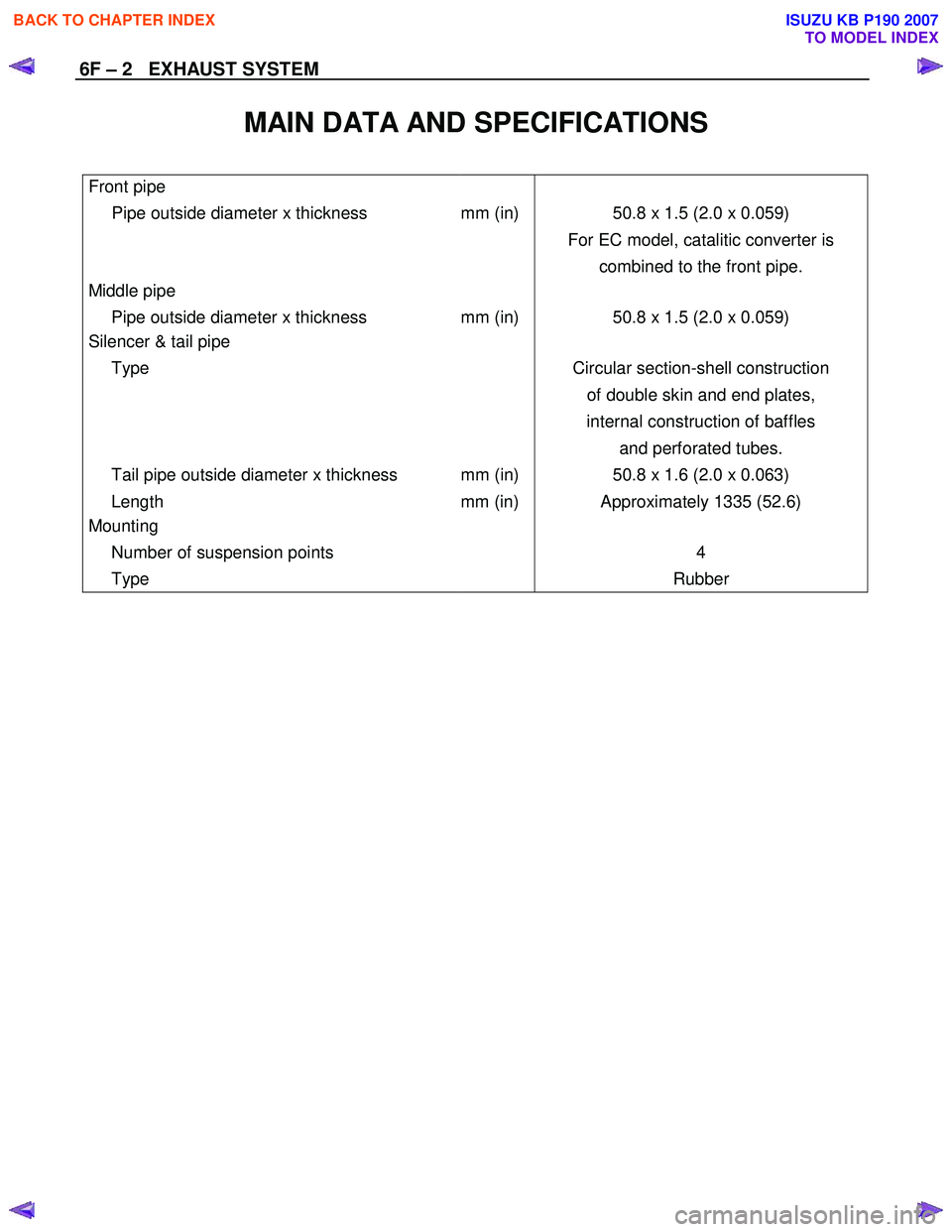
MAIN DATA AND SPECIFICATIONS
Front pipe
Pipe outside diameter x thickness mm (in) 50.8 x 1.5 (2.0 x 0.059)
For EC model, catalitic converter is
combined to the front pipe.
Middle pipe
Pipe outside diameter x thickness mm (in) 50.8 x 1.5 (2.0 x 0.059)
Silencer & tail pipe
Type Circular section-shell construction
of double skin and end plates,
internal construction of baffles
and perforated tubes.
Tail pipe outside diameter x thickness mm (in) 50.8 x 1.6 (2.0 x 0.063)
Length mm (in) Approximately 1335 (52.6)
Mounting
Number of suspension points 4
Type Rubber
BACK TO CHAPTER INDEX
TO MODEL INDEX
ISUZU KB P190 2007
Page 1435 of 6020
ENGINE MECHANICAL (4JK1/4JJ1) 6A-75
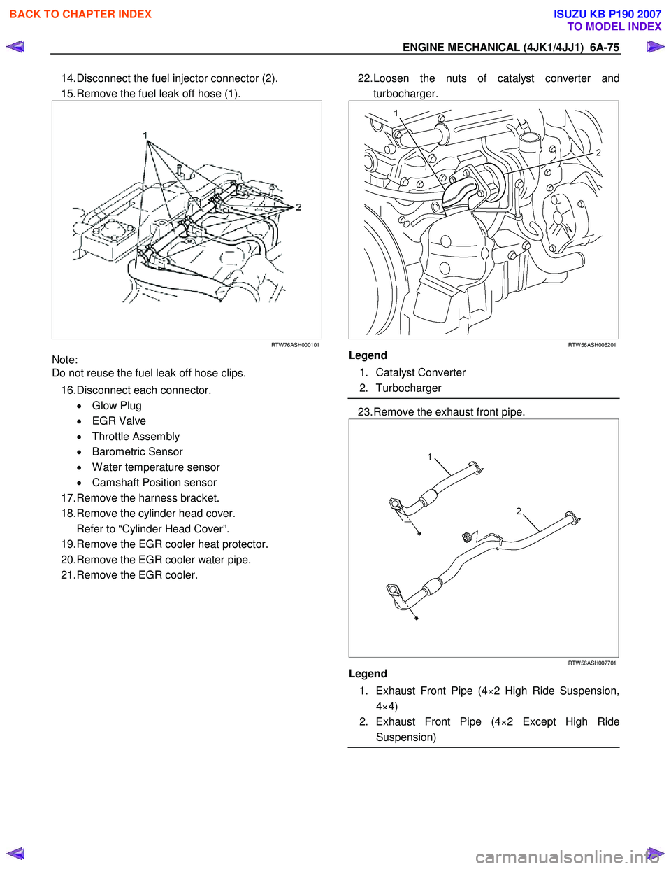
14. Disconnect the fuel injector connector (2).
15. Remove the fuel leak off hose (1).
RTW 76ASH000101
Note:
Do not reuse the fuel leak off hose clips.
16. Disconnect each connector. • Glow Plug
• EGR Valve
• Throttle Assembly
• Barometric Sensor
• W ater temperature sensor
• Camshaft Position sensor
17. Remove the harness bracket.
18. Remove the cylinder head cover.
Refer to “Cylinder Head Cover”.
19. Remove the EGR cooler heat protector.
20. Remove the EGR cooler water pipe.
21. Remove the EGR cooler.
22. Loosen the nuts of catalyst converter and
turbocharger.
RTW 56ASH006201
Legend
1. Catalyst Converter
2. Turbocharger
23. Remove the exhaust front pipe.
RTW 56ASH007701
Legend
1. Exhaust Front Pipe (4×2 High Ride Suspension, 4×4)
2. Exhaust Front Pipe (4×2 Except High Ride Suspension)
BACK TO CHAPTER INDEX
TO MODEL INDEX
ISUZU KB P190 2007
Page 1987 of 6020
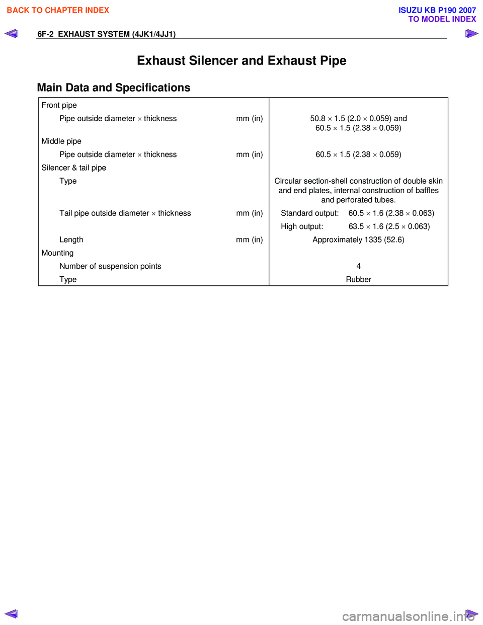
6F-2 EXHAUST SYSTEM (4JK1/4JJ1)
Exhaust Silencer and Exhaust Pipe
Main Data and Specifications
Front pipe
Pipe outside diameter × thickness mm (in)50.8 × 1.5 (2.0 × 0.059) and
60.5 × 1.5 (2.38 × 0.059)
Middle pipe
Pipe outside diameter × thickness mm (in)60.5 × 1.5 (2.38 × 0.059)
Silencer & tail pipe
Type Circular section-shell construction of double skin
and end plates, internal construction of baffles and perforated tubes.
Tail pipe outside diameter × thickness mm (in) Standard output: 60.5 × 1.6 (2.38 × 0.063)
High output: 63.5 × 1.6 (2.5 × 0.063)
Length mm (in)Approximately 1335 (52.6)
Mounting
Number of suspension points 4
Type Rubber
BACK TO CHAPTER INDEX
TO MODEL INDEX
ISUZU KB P190 2007
Page 1988 of 6020
EXHAUST SYSTEM (4JK1/4JJ1) 6F-3
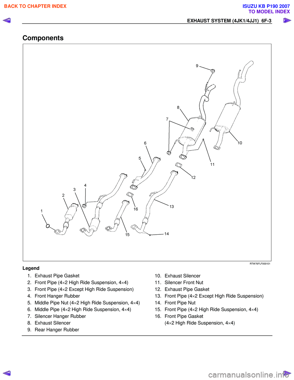
Components
RTW 76FLF000101
Legend
1. Exhaust Pipe Gasket
2. Front Pipe (4 ×2 High Ride Suspension, 4 ×4)
3. Front Pipe (4 ×2 Except High Ride Suspension)
4. Front Hanger Rubber
5. Middle Pipe Nut (4 ×2 High Ride Suspension, 4 ×4)
6. Middle Pipe (4 ×2 High Ride Suspension, 4 ×4)
7. Silencer Hanger Rubber
8. Exhaust Silencer
9. Rear Hanger Rubber
10. Exhaust Silencer
11. Silencer Front Nut
12. Exhaust Pipe Gasket
13. Front Pipe (4 ×2 Except High Ride Suspension)
14. Front Pipe Nut
15. Front Pipe (4 ×2 High Ride Suspension, 4 ×4)
16. Front Pipe Gasket
(4 ×2 High Ride Suspension, 4 ×4)
BACK TO CHAPTER INDEX
TO MODEL INDEX
ISUZU KB P190 2007
Page 1989 of 6020
6F-4 EXHAUST SYSTEM (4JK1/4JJ1)
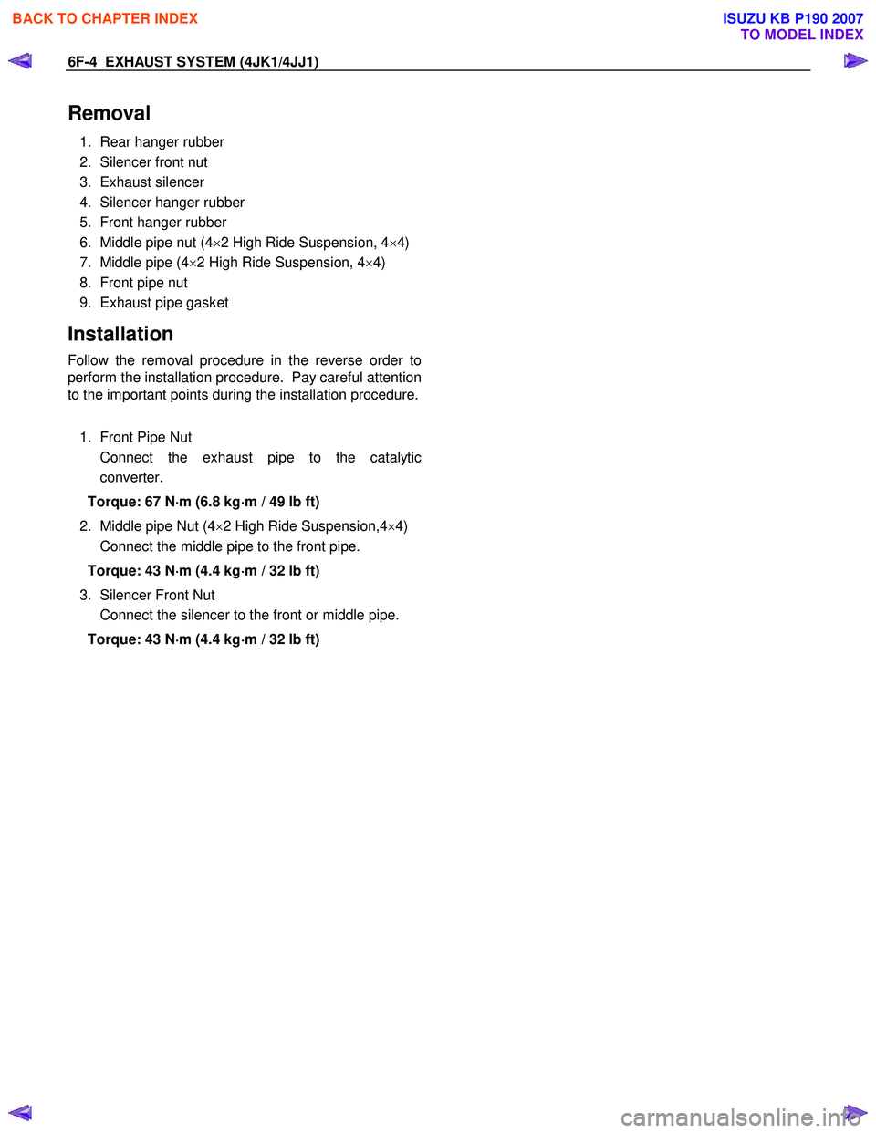
Removal
1. Rear hanger rubber
2. Silencer front nut
3. Exhaust silencer
4. Silencer hanger rubber
5. Front hanger rubber
6. Middle pipe nut (4 ×2 High Ride Suspension, 4 ×4)
7. Middle pipe (4 ×2 High Ride Suspension, 4 ×4)
8. Front pipe nut
9. Exhaust pipe gasket
Installation
Follow the removal procedure in the reverse order to
perform the installation procedure. Pay careful attention
to the important points during the installation procedure.
1. Front Pipe Nut
Connect the exhaust pipe to the catalytic converter.
Torque: 67 N ⋅
⋅⋅
⋅
m (6.8 kg ⋅
⋅⋅
⋅
m / 49 lb ft)
2. Middle pipe Nut (4 ×2 High Ride Suspension,4 ×4)
Connect the middle pipe to the front pipe.
Torque: 43 N ⋅
⋅⋅
⋅
m (4.4 kg ⋅
⋅⋅
⋅
m / 32 lb ft)
3. Silencer Front Nut
Connect the silencer to the front or middle pipe.
Torque: 43 N ⋅
⋅⋅
⋅
m (4.4 kg ⋅
⋅⋅
⋅
m / 32 lb ft)
BACK TO CHAPTER INDEX
TO MODEL INDEX
ISUZU KB P190 2007