Wiring harness ISUZU KB P190 2007 Workshop Repair Manual
[x] Cancel search | Manufacturer: ISUZU, Model Year: 2007, Model line: KB P190, Model: ISUZU KB P190 2007Pages: 6020, PDF Size: 70.23 MB
Page 3536 of 6020
Engine Management – V6 – Service Operations Page 6C1-3–12
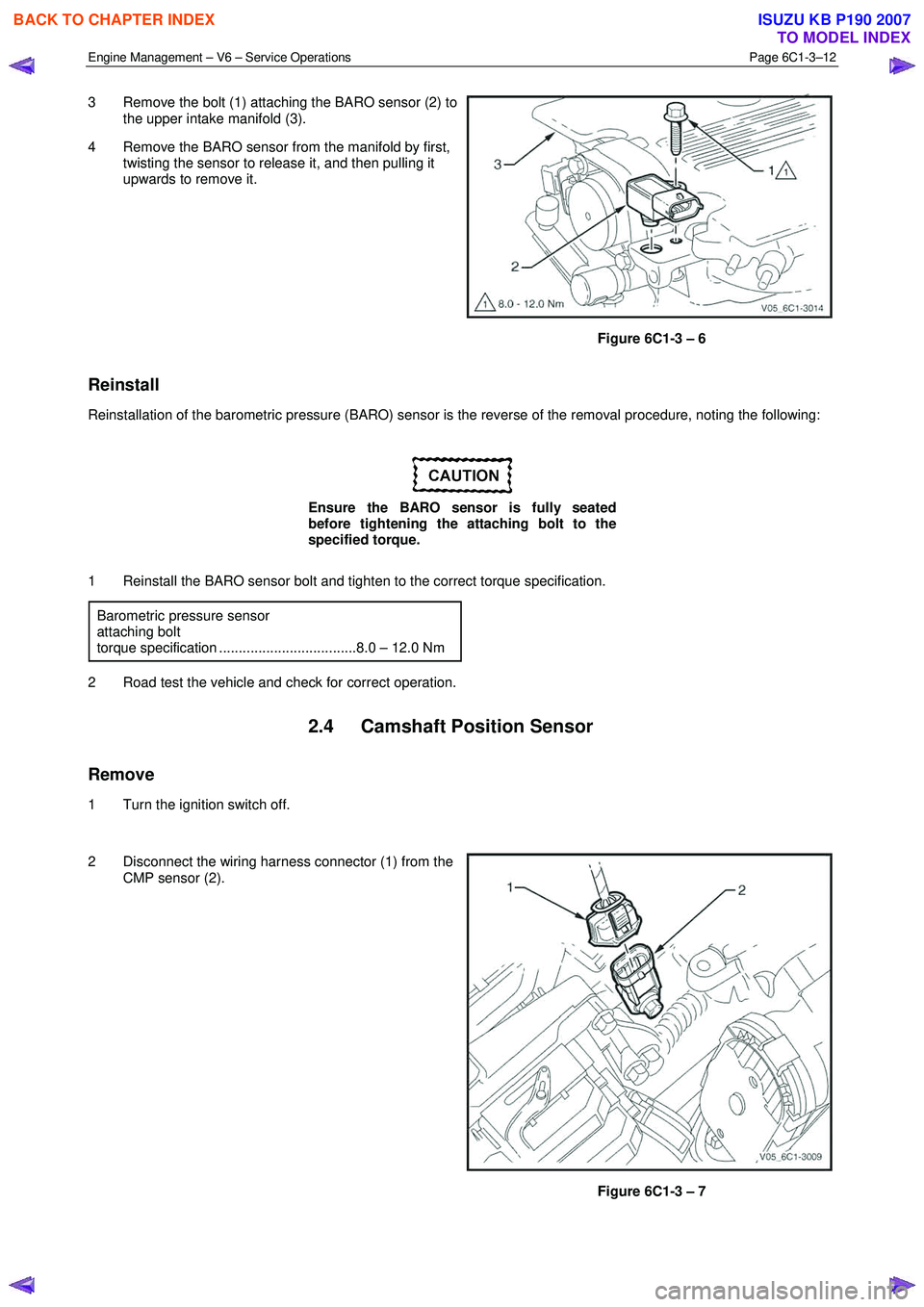
3 Remove the bolt (1) attaching the BARO sensor (2) to
the upper intake manifold (3).
4 Remove the BARO sensor from the manifold by first, twisting the sensor to release it, and then pulling it
upwards to remove it.
Figure 6C1-3 – 6
Reinstall
Reinstallation of the barometric pressure (BARO) sensor is the reverse of the removal procedure, noting the following:
Ensure the BARO sensor is fully seated
before tightening the attaching bolt to the
specified torque.
1 Reinstall the BARO sensor bolt and tighten to the correct torque specification. Barometric pressure sensor
attaching bolt
torque specification ...................................8.0 – 12.0 Nm
2 Road test the vehicle and check for correct operation.
2.4 Camshaft Position Sensor
Remove
1 Turn the ignition switch off.
2 Disconnect the wiring harness connector (1) from the CMP sensor (2).
Figure 6C1-3 – 7
BACK TO CHAPTER INDEX
TO MODEL INDEX
ISUZU KB P190 2007
Page 3538 of 6020
Engine Management – V6 – Service Operations Page 6C1-3–14
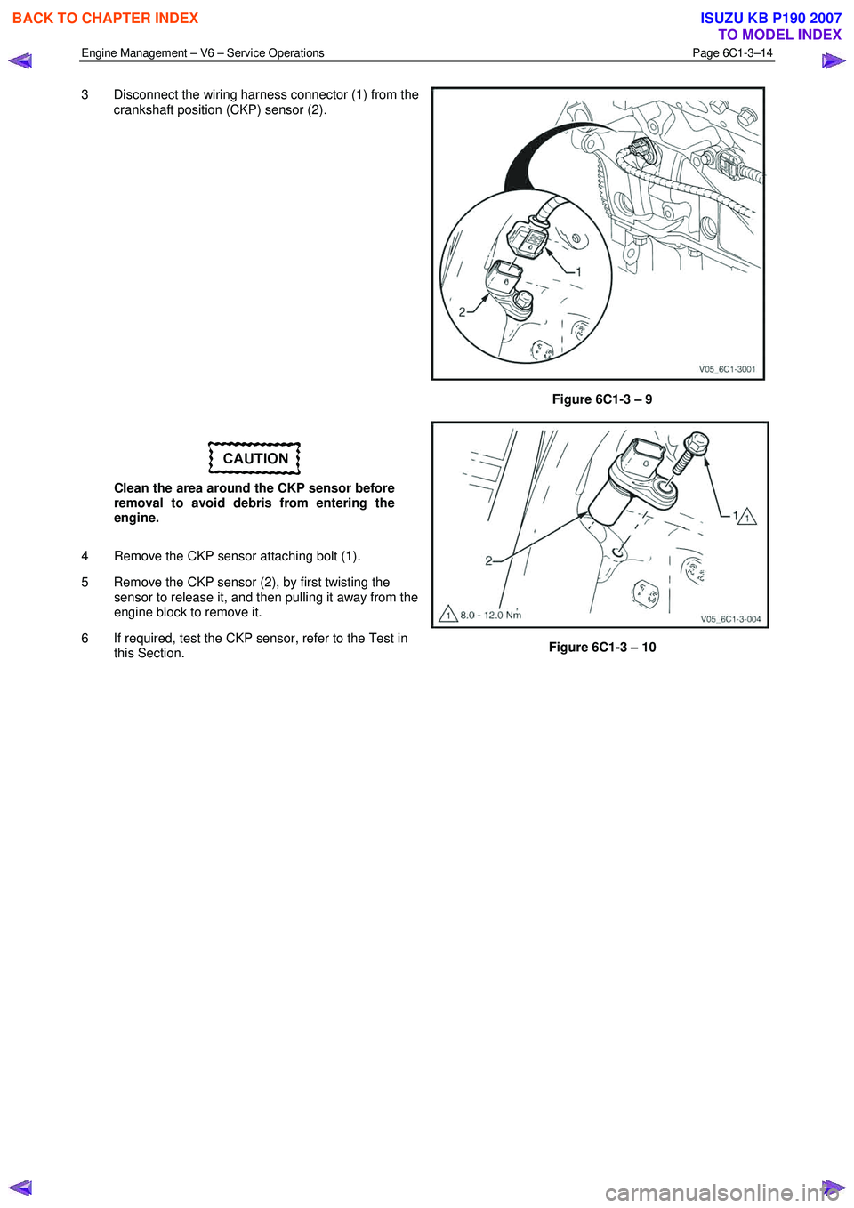
3 Disconnect the wiring harness connector (1) from the
crankshaft position (CKP) sensor (2).
Figure 6C1-3 – 9
Clean the area around the CKP sensor before
removal to avoid debris from entering the
engine.
4 Remove the CKP sensor attaching bolt (1).
5 Remove the CKP sensor (2), by first twisting the sensor to release it, and then pulling it away from the
engine block to remove it.
6 If required, test the CKP sensor, refer to the Test in this Section.
Figure 6C1-3 – 10
BACK TO CHAPTER INDEX
TO MODEL INDEX
ISUZU KB P190 2007
Page 3540 of 6020
Engine Management – V6 – Service Operations Page 6C1-3–16
2.6 Engine Coolant Temperature Sensor
Remove
To avoid serious personal injury, never
remove the engine coolant temperature (ECT)
sensor when the engine is hot. Allow the
engine to cool to ambient temperature (less
than 50 °
°°
°
C) before performing this procedure.
1 Turn the ignition switch off.
To avoid serious personal injury, never
remove the coolant filler cap when the engine
is hot. Allow the engine to cool to ambient
temperature (less than 50 °
°°
°
C) before
performing this procedure.
2 Allow the engine to cool to ambient temperature less than 50 °C, and slowly remove coolant filler cap located on the
coolant outlet housing.
3 Drain approximately two litres of coolant into a suitable container, refer to 6B1 – Engine Cooling – V6.
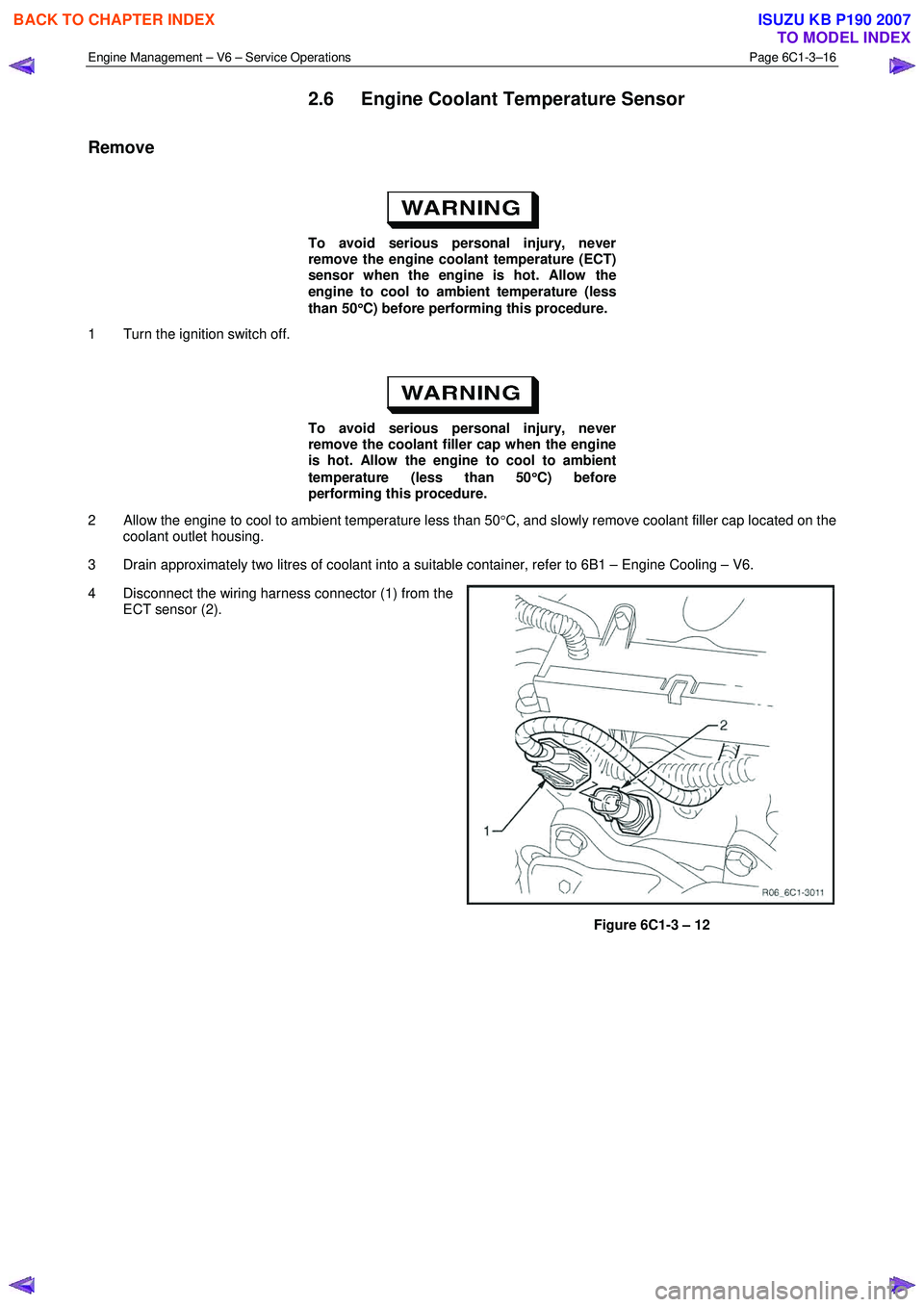
4 Disconnect the wiring harness connector (1) from the ECT sensor (2).
Figure 6C1-3 – 12
BACK TO CHAPTER INDEX
TO MODEL INDEX
ISUZU KB P190 2007
Page 3542 of 6020

Engine Management – V6 – Service Operations Page 6C1-3–18
5 If the resistance is not within specifications, replace
the ECT sensor.
Engine Coolant Temperature Vs Resistance
Temperature °C Resistance – Ohms (
Ω)
-40 40490 – 50136
-20 14096 – 16827
-10 8642 – 10152
0 5466 – 6326
20 2351 – 2649
25 1941 – 2173
40 1118 – 1231
60 573 – 618
80 313 – 332
100 182 – 191
120 109 – 116
140 68 – 74
Reinstall
Reinstallation of the engine coolant temperature (ECT) sensor is the reverse of the removal procedure, noting the
following:
1 Tighten the ECT sensor to the correct torque specification.
Engine coolant temperature sensor
torque specification ............................................22.0 Nm
2 Refill the cooling system, refer to 6B1 Engine Cooling – V6.
3 Road test the vehicle and check for correct operation, taking particular note there is no coolant leakage.
2.7 Engine Control Module
Service of the engine control module (ECM) should normally consist of either replacement or ECM programming. If the
diagnostic procedures call for the ECM to be replaced, it should be first checked to ensure it is the correct part. If it is,
replace the faulty ECM.
Do not touch the ECM connector pins as
electrostatic discharge (ESD) damage may
result.
When removing or reinstalling the ECM wiring
harness connector/s, ensure the ignition
switch is in the OFF position and the battery
has been disconnected. Failure to do so may
result in damage to the ECM and / or
associated componentry.
Disconnection of the battery affects certain
vehicle electronic systems. Refer to 6D1-3
Battery - V6 before disconnecting the battery.
BACK TO CHAPTER INDEX
TO MODEL INDEX
ISUZU KB P190 2007
Page 3544 of 6020
Engine Management – V6 – Service Operations Page 6C1-3–20
Reinstall
Reinstallation of the engine control module (ECM) is the reverse of the removal procedure, noting the following:
NOTE
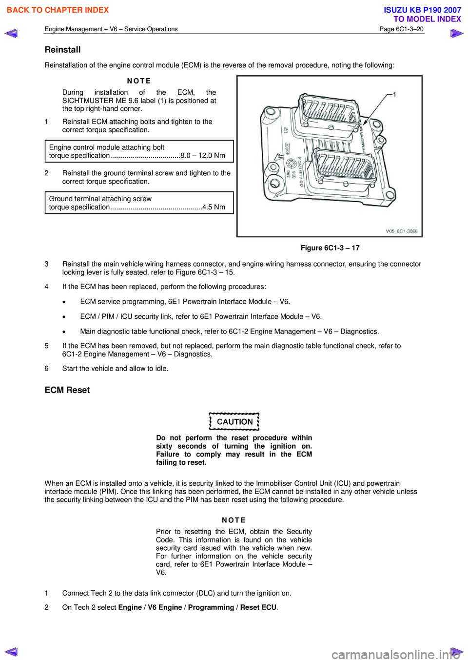
During installation of the ECM, the
SICHTMUSTER ME 9.6 label (1) is positioned at
the top right-hand corner.
1 Reinstall ECM attaching bolts and tighten to the correct torque specification.
Engine control module attaching bolt
torque specification ...................................8.0 – 12.0 Nm
2 Reinstall the ground terminal screw and tighten to the correct torque specification.
Ground terminal attaching screw
torque specification ..............................................4.5 Nm
Figure 6C1-3 – 17
3 Reinstall the main vehicle wiring harness connector, and engine wiring harness connector, ensuring the connector locking lever is fully seated, refer to Figure 6C1-3 – 15.
4 If the ECM has been replaced, perform the following procedures:
• ECM service programming, 6E1 Powertrain Interface Module – V6.
• ECM / PIM / ICU security link, refer to 6E1 Powertrain Interface Module – V6.
• Main diagnostic table functional check, refer to 6C1-2 Engine Management – V6 – Diagnostics.
5 If the ECM has been removed, but not replaced, perform the main diagnostic table functional check, refer to 6C1-2 Engine Management – V6 – Diagnostics.
6 Start the vehicle and allow to idle.
ECM Reset
Do not perform the reset procedure within
sixty seconds of turning the ignition on.
Failure to comply may result in the ECM
failing to reset.
W hen an ECM is installed onto a vehicle, it is security linked to the Immobiliser Control Unit (ICU) and powertrain
interface module (PIM). Once this linking has been performed, the ECM cannot be installed in any other vehicle unless
the security linking between the ICU and the PIM has been reset using the following procedure.
NOTE
Prior to resetting the ECM, obtain the Security
Code. This information is found on the vehicle
security card issued with the vehicle when new.
For further information on the vehicle security
card, refer to 6E1 Powertrain Interface Module –
V6.
1 Connect Tech 2 to the data link connector (DLC) and turn the ignition on.
2 On Tech 2 select Engine / V6 Engine / Programming / Reset ECU .
BACK TO CHAPTER INDEX
TO MODEL INDEX
ISUZU KB P190 2007
Page 3546 of 6020
Engine Management – V6 – Service Operations Page 6C1-3–22
3 Road test the vehicle and check for correct operation.
2.9 Engine Oil Level and Temperature
Sensor
To avoid personal injury, take care when
draining the engine oil or removing the engine
oil level and temperature sensor whilst the
engine is hot. Allow the engine to cool before
performing this procedure.
Remove
1 Turn the ignition switch off.
2 Raise the front and rear of the vehicle and support on safety stands, refer to 0A General Information for location of the jacking points.
3 Drain the engine oil, refer to 6A1 Engine Mechanical – V6.
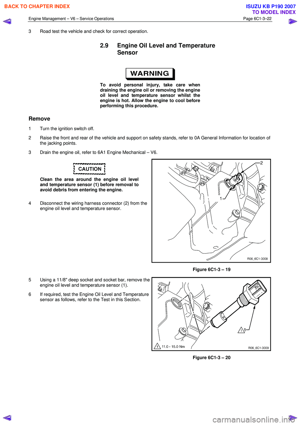
Clean the area around the engine oil level
and temperature sensor (1) before removal to
avoid debris from entering the engine.
4 Disconnect the wiring harness connector (2) from the engine oil level and temperature sensor.
Figure 6C1-3 – 19
5 Using a 11/8" deep socket and socket bar, remove the engine oil level and temperature sensor (1).
6 If required, test the Engine Oil Level and Temperature sensor as follows, refer to the Test in this Section.
Figure 6C1-3 – 20
BACK TO CHAPTER INDEX
TO MODEL INDEX
ISUZU KB P190 2007
Page 3548 of 6020
Engine Management – V6 – Service Operations Page 6C1-3–24
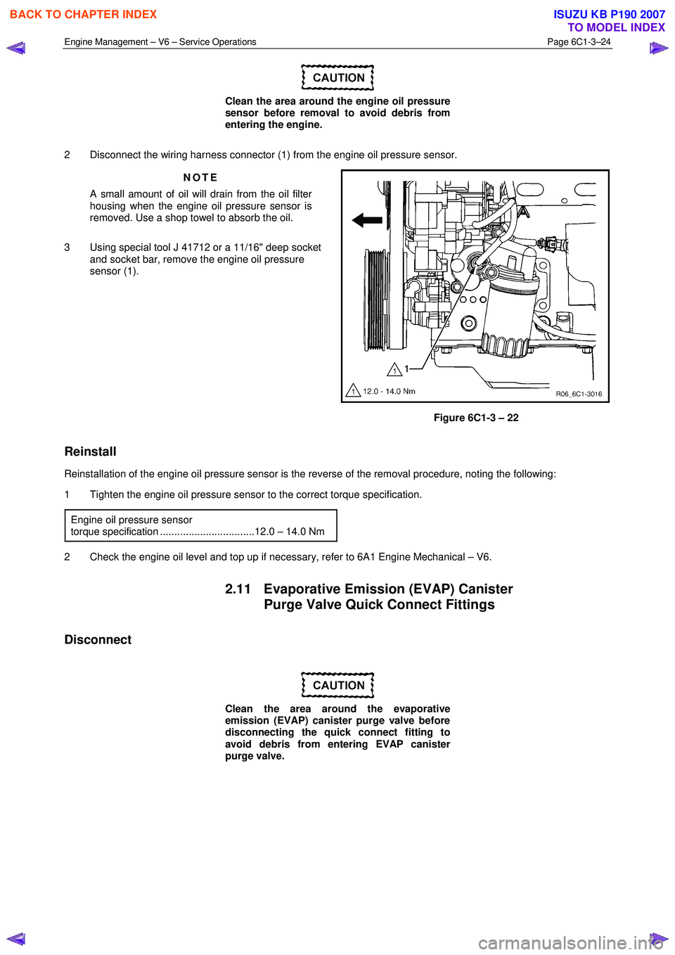
Clean the area around the engine oil pressure
sensor before removal to avoid debris from
entering the engine.
2 Disconnect the wiring harness connector (1) from the engine oil pressure sensor. NOTE
A small amount of oil will drain from the oil filter
housing when the engine oil pressure sensor is
removed. Use a shop towel to absorb the oil.
3 Using special tool J 41712 or a 11/16" deep socket and socket bar, remove the engine oil pressure
sensor (1).
Figure 6C1-3 – 22
Reinstall
Reinstallation of the engine oil pressure sensor is the reverse of the removal procedure, noting the following:
1 Tighten the engine oil pressure sensor to the correct torque specification.
Engine oil pressure sensor
torque specification .................................12.0 – 14.0 Nm
2 Check the engine oil level and top up if necessary, refer to 6A1 Engine Mechanical – V6.
2.11 Evaporative Emission (EVAP) Canister Purge Valve Quick Connect Fittings
Disconnect
Clean the area around the evaporative
emission (EVAP) canister purge valve before
disconnecting the quick connect fitting to
avoid debris from entering EVAP canister
purge valve.
BACK TO CHAPTER INDEX
TO MODEL INDEX
ISUZU KB P190 2007
Page 3550 of 6020
Engine Management – V6 – Service Operations Page 6C1-3–26
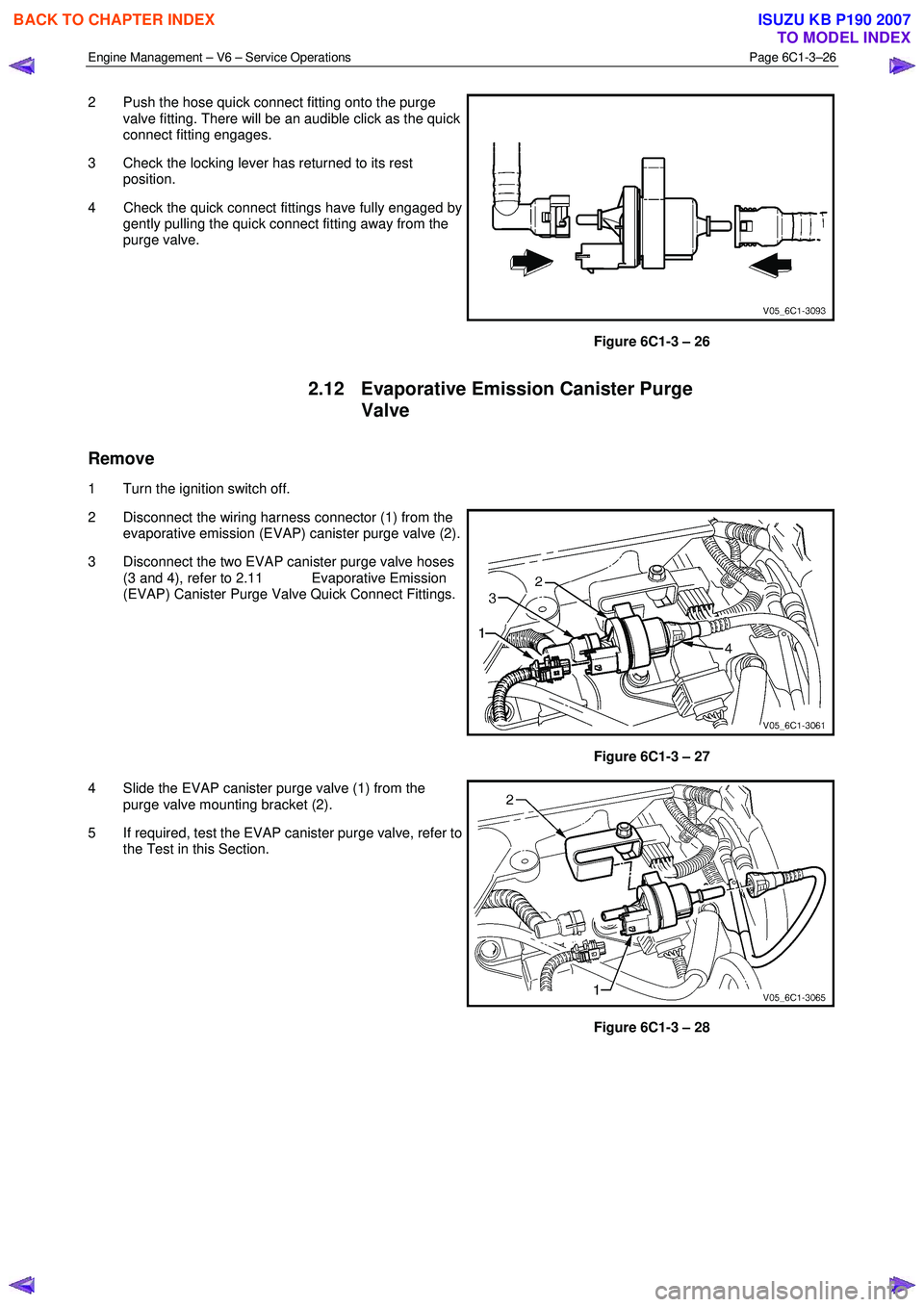
2 Push the hose quick connect fitting onto the purge
valve fitting. There will be an audible click as the quick
connect fitting engages.
3 Check the locking lever has returned to its rest position.
4 Check the quick connect fittings have fully engaged by gently pulling the quick connect fitting away from the
purge valve.
Figure 6C1-3 – 26
2.12 Evaporative Emission Canister Purge
Valve
Remove
1 Turn the ignition switch off.
2 Disconnect the wiring harness connector (1) from the evaporative emission (EVAP) canister purge valve (2).
3 Disconnect the two EVAP canister purge valve hoses (3 and 4), refer to 2.11 Evaporative Emission
(EVAP) Canister Purge Valve Quick Connect Fittings.
Figure 6C1-3 – 27
4 Slide the EVAP canister purge valve (1) from the purge valve mounting bracket (2).
5 If required, test the EVAP canister purge valve, refer to the Test in this Section.
Figure 6C1-3 – 28
BACK TO CHAPTER INDEX
TO MODEL INDEX
ISUZU KB P190 2007
Page 3553 of 6020
Engine Management – V6 – Service Operations Page 6C1-3–29
NOTE
After removing the upper intake manifold, plug
the lower manifold opening to prevent dirt and
other contaminants from entering.
3 Remove the upper intake manifold assembly, refer to 6A1 Engine Mechanical – V6.
4 Disconnect the fuel feed hose from the fuel rail, refer to 6C Fuel System - V6. Plug the fuel line openings to prevent dirt and other contaminants from entering.
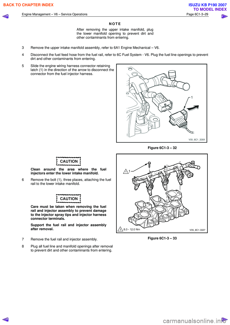
5 Slide the engine wiring harness connector retaining latch (1) in the direction of the arrow to disconnect the
connector from the fuel injector harness.
Figure 6C1-3 – 32
Clean around the area where the fuel
injectors enter the lower intake manifold.
6 Remove the bolt (1), three places, attaching the fuel rail to the lower intake manifold.
Care must be taken when removing the fuel
rail and injector assembly to prevent damage
to the injector spray tips and injector harness
connector terminals.
Support the fuel rail and injector assembly
after removal.
7 Remove the fuel rail and injector assembly.
8 Plug all fuel line and manifold openings after removal to prevent dirt and other contaminants from entering.
Figure 6C1-3 – 33
BACK TO CHAPTER INDEX
TO MODEL INDEX
ISUZU KB P190 2007
Page 3556 of 6020
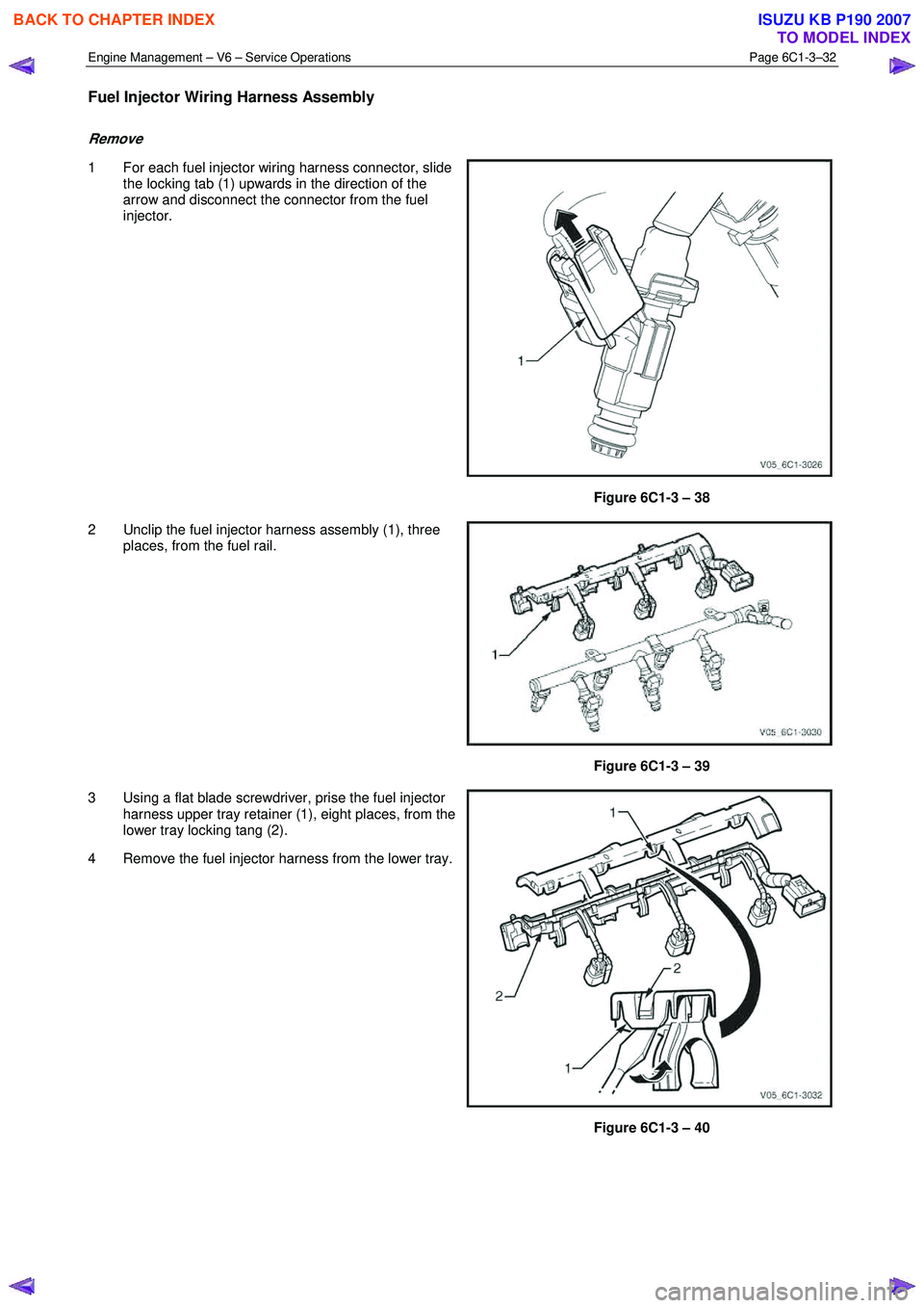
Engine Management – V6 – Service Operations Page 6C1-3–32
Fuel Injector Wiring Harness Assembly
Remove
1 For each fuel injector wiring harness connector, slide
the locking tab (1) upwards in the direction of the
arrow and disconnect the connector from the fuel
injector.
Figure 6C1-3 – 38
2 Unclip the fuel injector harness assembly (1), three places, from the fuel rail.
Figure 6C1-3 – 39
3 Using a flat blade screwdriver, prise the fuel injector harness upper tray retainer (1), eight places, from the
lower tray locking tang (2).
4 Remove the fuel injector harness from the lower tray.
Figure 6C1-3 – 40
BACK TO CHAPTER INDEX
TO MODEL INDEX
ISUZU KB P190 2007