Wiring harness ISUZU KB P190 2007 Workshop Repair Manual
[x] Cancel search | Manufacturer: ISUZU, Model Year: 2007, Model line: KB P190, Model: ISUZU KB P190 2007Pages: 6020, PDF Size: 70.23 MB
Page 3596 of 6020

Charging System – V6 Page 6D1-1-9
2.5 Charging System Inoperative /
Malfunctioning
Diagnostic Table Notes
Reference to following information will assist when diagnosing charging system faults.
1 For all wiring harness fault diagnoses, refer to 8A Electrical Body and Chassis.
2 For wiring harness repairs, refer to 8A Electrical Body and Chassis.
3 Refer to 8A Electrical Body and Chassis for harness routing.
4 Ensure the battery, cables and connections are in good order. Refer to 6D1-3 Battery – V6.
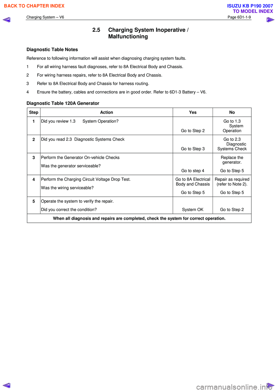
Diagnostic Table 120A Generator
Step Action Yes No
1 Did you review 1.3 System Operation?
Go to Step 2 Go to 1.3
System Operation
2 Did you read 2.3 Diagnostic Systems Check
Go to Step 3 Go to 2.3
Diagnostic
Systems Check
3 Perform the Generator On-vehicle Checks
W as the generator serviceable? Go to step 4 Replace the
generator.
Go to Step 5
4 Perform the Charging Circuit Voltage Drop Test.
W as the wiring serviceable? Go to 8A Electrical
Body and Chassis
Go to Step 5 Repair as required
(refer to Note 2).
Go to Step 5
5 Operate the system to verify the repair.
Did you correct the condition? System OK Go to Step 2
When all diagnosis and repairs are completed, check the system for correct operation.
BACK TO CHAPTER INDEX
TO MODEL INDEX
ISUZU KB P190 2007
Page 3598 of 6020

Charging System – V6 Page 6D1-1-11
3.3 On-vehicle Testing
Generator On-vehicle Checks
Prerequisites
Before testing the generator output, ensure that:
• all generator circuit connections are clean and tight,
• the generator is always connected to the battery during testing (to prevent damage to the diodes),
• the battery is fully charged, and
• the specific gravity does not vary more than 0.025 between cells. (It is recommended the average specific gravity
is 1.260 or higher). Refer to 6D1-3 Battery – V6.
Carry out a load test on the battery to determine its ability to supply and accept current. This is a good indicator of the
general condition of the battery. For details of battery testing, refer to 6D1-3 Battery – V6.
Inspect the drive belt and tensioner markings to determine if the drive belt is within operating limits. Replace the belt if it
is excessively worn or outside the operating range of the tensioner.
For further details, refer to 6A1 Engine Mechanical – V6.
Generator Test
Regulating Voltage Test
NOTE
Leave the generator E-4 wiring harness
connector connected, as it provides initial field
excitation.
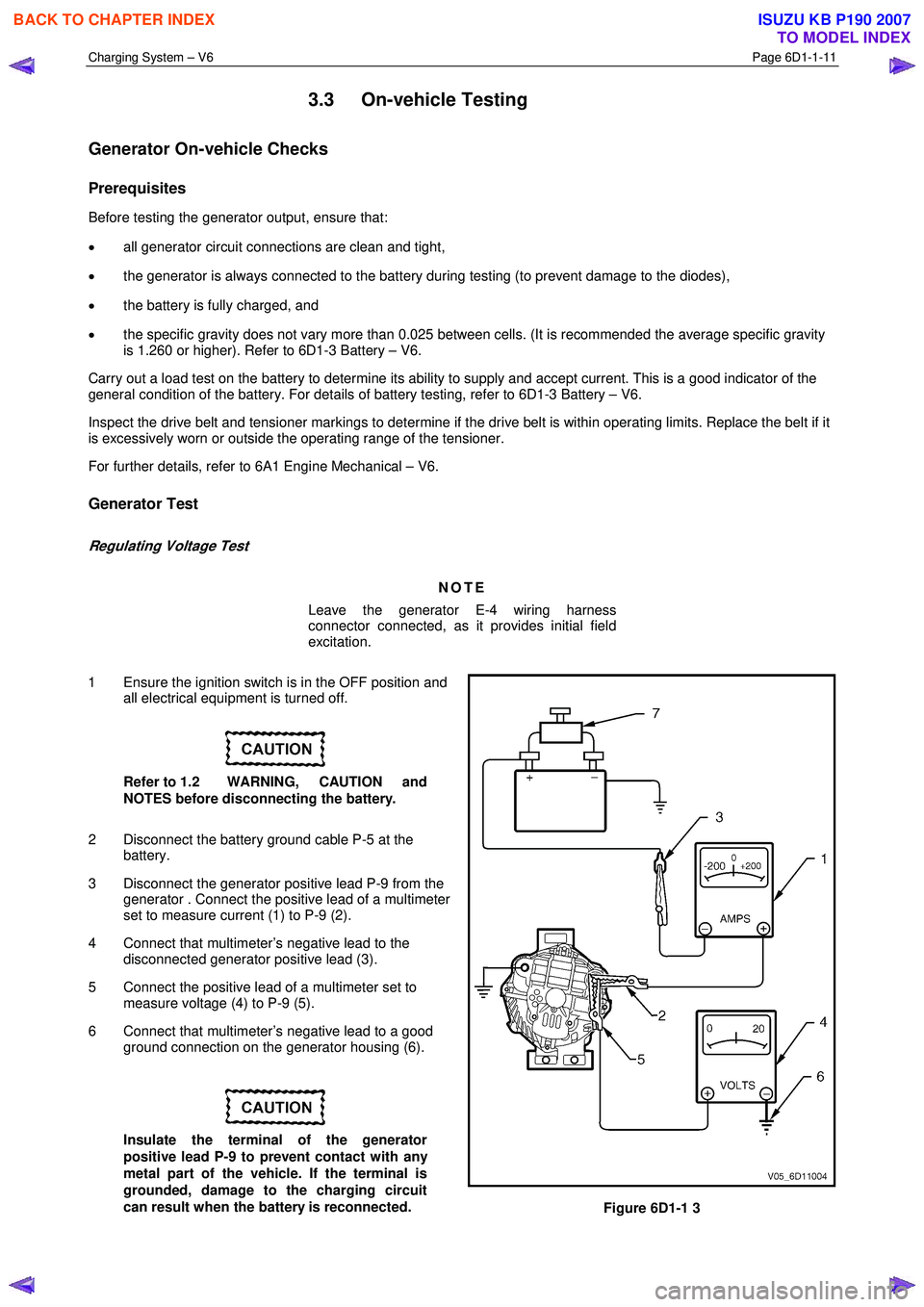
1 Ensure the ignition switch is in the OFF position and all electrical equipment is turned off.
Refer to 1.2 WARNING, CAUTION and
NOTES before disconnecting the battery.
2 Disconnect the battery ground cable P-5 at the battery.
3 Disconnect the generator positive lead P-9 from the generator . Connect the positive lead of a multimeter
set to measure current (1) to P-9 (2).
4 Connect that multimeter’s negative lead to the disconnected generator positive lead (3).
5 Connect the positive lead of a multimeter set to measure voltage (4) to P-9 (5).
6 Connect that multimeter’s negative lead to a good ground connection on the generator housing (6).
Insulate the terminal of the generator
positive lead P-9 to prevent contact with any
metal part of the vehicle. If the terminal is
grounded, damage to the charging circuit
can result when the battery is reconnected.
Figure 6D1-1 3
BACK TO CHAPTER INDEX
TO MODEL INDEX
ISUZU KB P190 2007
Page 3618 of 6020

Starting System – V6 Page 6D1-2–10
2.5 Starting System Inoperative /
Malfunctioning
Circuit Description
The battery cable supplies a constant connection from the battery to starter solenoid connector P – 4.
W hen the ignition switch is turned to the START position, 12 V is applied to the ECM connector C – 56 pin 31.
For vehicles with 4 speed automatic transmission, when the transmission is in park (P) or neutral (N), the park / neutral
and back-up switch grounds ECM connector C – 56 pin 32.
The ECM provides a ground for the start relay, ECM connector C – 56 pin 35 to start relay connector X – 13 pin 5.
W hen activated the start relay provides 12 V to starter solenoid connector P – 3 pin 1.
The solenoid closes its switch contacts to connect the battery voltage at the solenoid switch terminal P – 4 terminal B to
the DC motor. The pull-in winding of the solenoid switch is grounded through the DC motor winding and brushes. The
hold-in winding is grounded through the solenoid casing. The DC motor is grounded through the starter motor casing.
Refer to 2.4 W iring Diagram to aid in diagnosis.
Diagnostic Table Notes
Reference to following information will assist when diagnosing starting circuit faults:
1 If the battery, starter motor and fuel system are deemed as serviceable and a ‘no crank’ and / or ‘no start’ condition exists, refer to the following Sections as required:
a 11A Immobiliser for theft deterrent engine crank inhibitor related faults
b 6C1-2 Engine Management V6 Diagnostics, for starter relay circuit faults
2 For all wiring harness fault diagnoses, refer to 8A Electrical Body and Chassis.
3 For wiring harness repairs, refer to 8A Electrical Body and Chassis.
4 Refer to 8A Electrical Body and Chassis for harness routing.
5 Ensure the battery, cables and connections are in good order. Refer to 8A Electrical Body and Chassis.
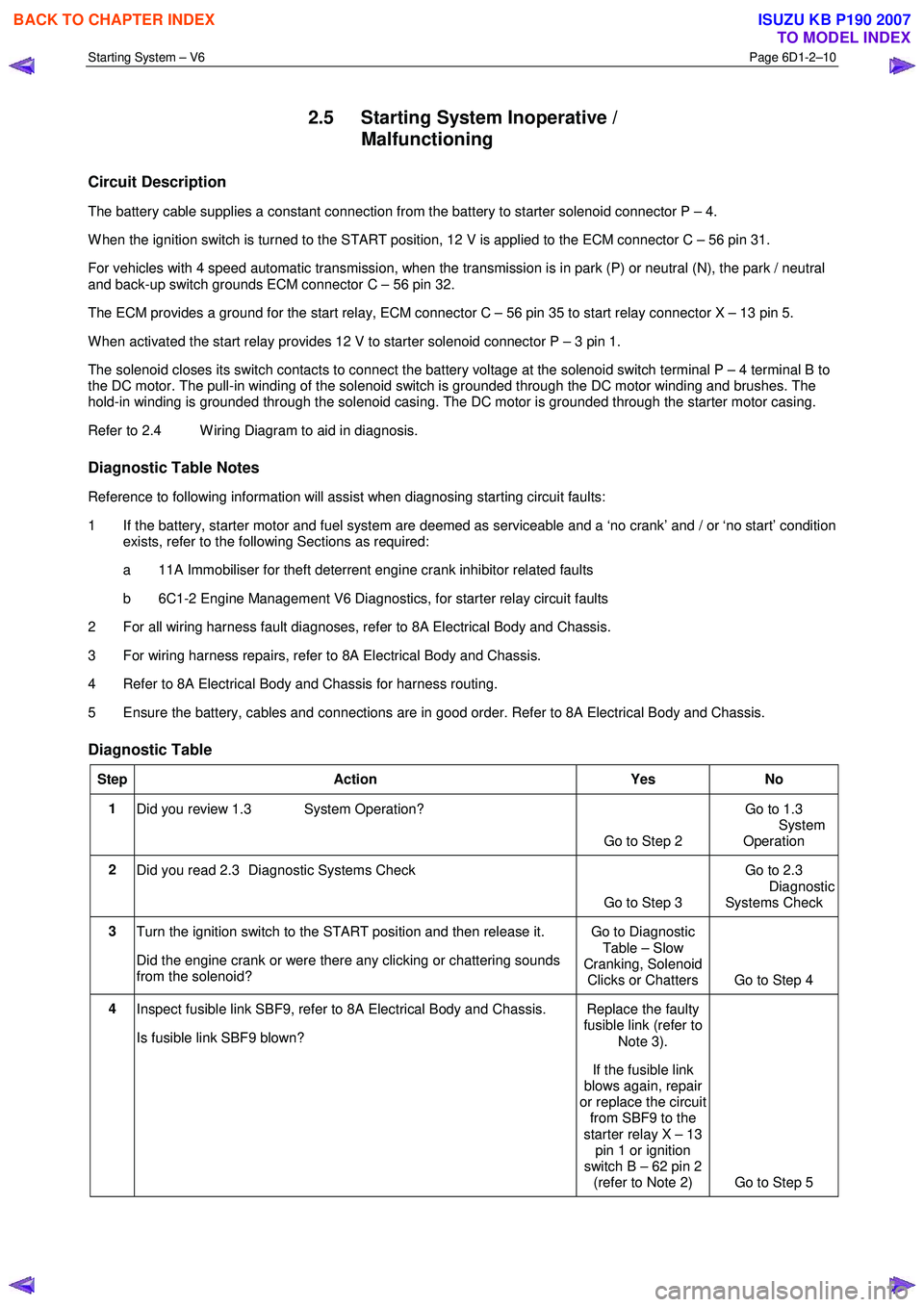
Diagnostic Table
Step Action Yes No
1
Did you review 1.3 System Operation?
Go to Step 2 Go to 1.3
System
Operation
2 Did you read 2.3 Diagnostic Systems Check
Go to Step 3 Go to 2.3
Diagnostic Systems Check
3 Turn the ignition switch to the START position and then release it.
Did the engine crank or were there any clicking or chattering sounds
from the solenoid? Go to Diagnostic
Table – Slow
Cranking, Solenoid Clicks or Chatters Go to Step 4
4 Inspect fusible link SBF9, refer to 8A Electrical Body and Chassis.
Is fusible link SBF9 blown? Replace the faulty
fusible link (refer to
Note 3).
If the fusible link
blows again, repair
or replace the circuit from SBF9 to the
starter relay X – 13 pin 1 or ignition
switch B – 62 pin 2 (refer to Note 2) Go to Step 5
BACK TO CHAPTER INDEX
TO MODEL INDEX
ISUZU KB P190 2007
Page 3629 of 6020

Starting System – V6 Page 6D1-2–21
10 Unclip the oil level sensor harness from the heat shield
(1).
11 Remove the heat shield attaching screw (2).
12 Remove the lower starter motor attaching bolt (3).
13 Remove the heat shield.
14 Remove the upper starter motor retaining bolt (3).
15 Remove the starter motor from the engine block and lower the starter motor as far as possible to gain
access to the wiring harness connections.
Figure 6D1-2 – 12
16 Remove the wiring harness connector P – 3 (1) from the solenoid switch (2).
17 Remove the flange nut (3) and battery connector P – 4 (4) from the solenoid switch.
18 Remove the starter motor from the vehicle.
Figure 6D1-2 – 13
Reinstall
Reinstallation of the starter motor is the reverse of the removal procedure noting the following:
1 Tighten all fasteners to the correct torque specification.
Solenoid switch connector P – 4 nut (B+)
torque specification ............................................10.0 Nm
Starter motor heat shield lower bolts
torque specification ............................................23.0 Nm
Starter motor heat shield upper screw
torque specification .....................................3.0 – 5.0 Nm
Starter motor mounting bolt
torque specification ............................................45.0 Nm
Knock sensor bolt
torque specification ............................................23.0 Nm
2 Check the starter motor operates correctly.
BACK TO CHAPTER INDEX
TO MODEL INDEX
ISUZU KB P190 2007
Page 3647 of 6020

Battery Page 6D1-3–7
3 Diagnosis
3.1 Diagnostic Procedures
Introduction
This test is used to aid in diagnosing faults with the vehicle where the battery seems to be at fault.
W ith the increased use of electronic sensors and computer control, the battery is much more than just a component used
to start a car. Low battery voltage can:
• affect the operation of the vehicle control modules and cause driveability problems, and
• cause the control modules to set diagnostic trouble codes (DTCs).
For example if a control module senses low battery voltage, it may increase fuel injector timing to increase engine rpm to
increase the generator output.
Therefore consider the state of charge of the battery any time a customer complains of a driveability related problem.
Test Description
The following numbers refer to the step numbers in the diagnostic table:
1 Checks the operator understands the safety precautions for working with batteries.
2 Checks if the vehicle is fitted with a battery of the correct specification.
3 Checks if the battery appears serviceable by performing the battery inspection procedure.
4 Checks if the battery loses charge over an extended period. If so the likely problem is excess current draw while the vehicles ignition is in the off position.
5 Checks the state of charge of the battery.
6 Checks if the battery is capable of delivering the required load by performing the load test procedure.
Diagnostic Table Notes
1 For all wiring harness fault diagnosis, refer to 8A Electrical Body & Chassis.
2 For wiring harness repairs, refer to 8A Electrical Body & Chassis.
3 Refer to 6D1 – 3 Battery – V6.
Diagnostic Table
Step Action Yes No
1
Have you read and understood the safety precautions for working with
batteries? Go to Step 2 Refer to 2
Safety Precautions
2 Check the battery fitted is the correct specification recommended for
the vehicle? Refer to 5 Specifications.
Is the battery the correct specification? Go to Step 3 Replace the battery
with the correct
specification
3 Perform the battery inspection, refer to 3.2 Battery Inspection.
Does the battery appear serviceable? Go to Step 4 Replace the battery,
refer to 4.1
Battery
4 Does the customer complain the battery loses charge if the engine is
not started for an extended period? Preform the battery
current draw test, refer to 3.5
Battery
Current Draw Test Go to Step 5
BACK TO CHAPTER INDEX
TO MODEL INDEX
ISUZU KB P190 2007
Page 3653 of 6020

Battery Page 6D1-3–13
3 W hen the circuit group is determined, install the fuse / circuit breaker and identify the specific circuit within this
group that is drawing the excess current. Disconnect the wiring harness connectors in this circuit group one at a
time. Refer to 8A Electrical Body & Chassis.
4 W hen the cause is disconnected, the multimeter reading should drop to the correct reading as outlined in Step 9 of the Test Procedure in this Section.
5 If required, remove the components in this circuit one at a time to determine the cause of the excessive standing current. Refer to 8A Electrical Body & Chassis.
6 Repair the fault, refer to 8A Electrical Body & Chassis.
7 Ensure any fuses, circuit breakers and connectors that have been removed are secure.
Restore
1 Reconnect the electrical earth cable to the battery terminal and tighten the nut to the correct torque specification.
Battery terminal nut
torque specification .....................................2.0 – 5.0 Nm
2 Disconnect the multimeter connections.
BACK TO CHAPTER INDEX
TO MODEL INDEX
ISUZU KB P190 2007
Page 3677 of 6020

Powertrain Interface Module – V6 Page 6E1–16
Tech 2 PIM Diagnostic Tests
Tech 2 Limitations
Some DTCs trigger other DTCs to set, which causes Tech 2 to display multiple DTCs. In those situations, Tech 2 may
display more DTCs than is needed to rectify a fault.
W hen Tech 2 displays an output function, it displays only the command given by the PIM. If a connector is disconnected,
that fault will not register in the PIM output function. Tech 2 does not verify the command action.
The service technician must understand the system being diagnosed as well as the correct use and limitations of Tech 2
to be able to perform diagnostic procedures efficiently and successfully.
Tech 2 Intermittent Fault Tests
The following are lists of Tech 2 diagnostic tests that may be used to diagnose intermittent faults:
• W iggle test the suspected PIM wiring harness and connector while observing Tech 2 operating parameters of the
circuit being tested. If Tech 2 read-out fluctuates during this procedure, check the wiring harness circuit for loose
connection.
• Road test the vehicle in conditions that trigger the intermittent fault while an assistant observes the suspected Tech
2 operating parameter data.
• Capture and store data in the Snapshot mode when the fault occurs. The stored data may be replayed at a slower
rate to aid in diagnostics. Refer to Tech 2 User Instructions for more information on the Snapshot function.
• Operate suspected components to test their operation using Tech 2 Output Control Data.
BACK TO CHAPTER INDEX
TO MODEL INDEX
ISUZU KB P190 2007
Page 3686 of 6020

Powertrain Interface Module – V6 Page 6E1–25
• Thorough inspection of the wiring circuits and connectors listed in the diagnostic procedures must be performed,
otherwise misdiagnosis may occur.
• Inspect the electrical circuitry or connector terminals that are suspected to be causing the complaint for the
following conditions:
• backed-out connector terminals,
• improper wiring connector mating,
• broken wiring connector locks,
• damaged connector terminals, and
• physical damage to the wiring harness.
• Before replacing a component, inspect its connector terminal for corrosion or deformation that may cause the fault
condition.
Preliminary Checks
The PIM preliminary check examines easily accessible components which may cause problems with the PIM. This visual
and physical inspection procedure may quickly identify the fault condition and eliminate the need for additional diagnosis.
• Refer to Service Techlines for relevant information regarding the fault condition.
• Ensure the battery is fully charged.
• Check the battery connections for corrosion or a loose terminal.
• Perform a visual and physical inspection of the following:
• PIM component wiring harness and terminals for proper connections, pinches or cuts, and
• PIM wiring harness routing which may be positioned very close to a high voltage or high current devices such
as aftermarket audio systems.
NOTE
High voltage or high current devices may induce
electrical noise on a circuit, which can interfere
with normal circuit operation.
• The PIM is sensitive to Electro Magnetic Interference (EMI). Check for incorrect aftermarket theft deterrent
devices, lights or mobile phone installations if an intermittent malfunction is suspected.
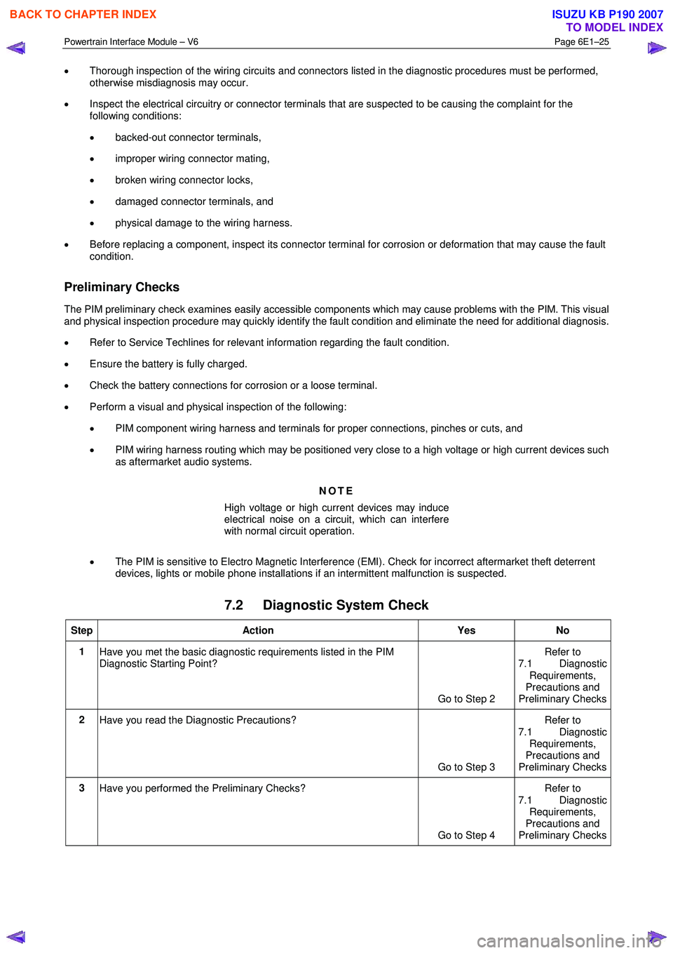
7.2 Diagnostic System Check
Step Action Yes No
1
Have you met the basic diagnostic requirements listed in the PIM
Diagnostic Starting Point?
Go to Step 2 Refer to
7.1 Diagnostic
Requirements,
Precautions and
Preliminary Checks
2 Have you read the Diagnostic Precautions?
Go to Step 3 Refer to
7.1 Diagnostic Requirements,
Precautions and
Preliminary Checks
3 Have you performed the Preliminary Checks?
Go to Step 4 Refer to
7.1 Diagnostic Requirements,
Precautions and
Preliminary Checks
BACK TO CHAPTER INDEX
TO MODEL INDEX
ISUZU KB P190 2007
Page 3688 of 6020

Powertrain Interface Module – V6 Page 6E1–27
7.3 Powertrain Interface Module – Module
Communication Check Failure
Diagnostic Table
Step Action Yes No
1
Has the Diagnostic System Check been performed?
Go to Step 2 Refer to
7.2 Diagnostic System Check
2 Test the following PIM circuits for a high resistance, open circuit or
short to ground fault condition. Refer to 8A Electrical - Body and
Chassis for information on electrical diagnosis:
• 12 V battery supply circuit,
• 12 V ignition circuit, and
• ground circuit.
Has any fault been found and rectified? Go to Step 10 Go to Step 3
3 1 Disconnect the ECM harness connector.
2 Switch off the ignition for 10 seconds.
3 Using Tech 2, attempt to communicate with the PIM.
NOTE
Other DTCs may set when the ECM connector is
disconnected and the ignition is switched on. Disregard
DTCs that set under this condition on this DTC Table.
Does Tech 2 communicate with the PIM? Go to Step 4 For vehicles with
automatic
transmissions, go to
Step 5. For vehicles with manual
transmission go to Step 8
4 Replace the ECM. Refer to 6C1-3 Engine Management – V6 –
Service Operations.
Has the repair been completed? Go to Step 10 —
5 1 Disconnect the TCM harness connector.
2 Switch off the ignition for 10 seconds.
3 Using Tech 2, attempt to communicate with the PIM.
Does Tech 2 communicate with the PIM? Go to Step 6 Go to Step 8
6 Test serial data circuits between the TCM and ECM for a short to
voltage, short to ground or short together condition.
Has any fault been found and rectified? Go to Step 10 Go to Step 7
7 Replace the TCM. Refer to 7C4 Automatic Transmission – 4L60E –
On-vehicle Servicing.
Has the repair been completed? Go to Step 10 —
8 Test serial data circuits between the PIM and ECM for vehicles with
manual transmission, or between the PIM and TCM for vehicles with
automatic transmission for a high resistance or open circuit fault
condition. Refer to 8A Electrical - Body and Chassis for information on
wiring circuit testing and repair.
Has any fault been found and rectified? Go to Step 10 Go to Step 9
9 Replace the PIM. Refer to 11.2 Powertrain Interface Module.
Has the repair been completed? Go to Step 10 —
10 Using Tech 2, attempt to communicate with the PIM.
Does Tech 2 communicate with the PIM? Go to Step 11 Refer to
7.2 Diagnostic System Check
BACK TO CHAPTER INDEX
TO MODEL INDEX
ISUZU KB P190 2007
Page 3695 of 6020

Powertrain Interface Module – V6 Page 6E1–34
Step Action Yes No
2
1 Switch off the ignition for 10 seconds.
2 Operate the vehicle within the conditions for setting DTC U2100.
3 Using Tech 2, select the DTC display function.
Does DTC U2100 fail this ignition cycle? Go to Step 3 Refer to
Additional
Information in this
Section
3 1 Disconnect the ECM harness connector.
2 Switch off the ignition for 10 seconds.
3 Operate the vehicle within the conditions for setting DTC U2100.
4 Using Tech 2, select the DTC display function and check if DTC U2100 fails this ignition cycle.
NOTE
Other DTCs may set when the ECM connector is
disconnected and the ignition is switched on. Disregard
DTCs that set under this condition on this DTC Table.
Does DTC U2100 fail this ignition cycle? For vehicles with
automatic
transmissions, go to Step 5. For vehicles
with manual
transmission go to Step 8 Go to Step 4
4
Replace the ECM. Refer to 6C1-3 Engine Management – V6 –
Service Operations.
Has the repair been completed? Go to Step 11 —
5 1 Disconnect the TCM harness connector.
2 Switch off the ignition for 10 seconds.
3 Using Tech 2, attempt to communicate with the PIM.
Does Tech 2 communicate with the PIM? Go to Step 6 Go to Step 8
6 Test serial data circuits between the TCM and ECM for a short to
voltage, short to ground or short together condition. Refer to 8A
Electrical - Body and Chassis for information on wiring circuit testing
and repair.
Has any fault been found and rectified? Go to Step 11 Go to Step 7
7
Replace the TCM. Refer to 7C4 Automatic Transmission – 4L60E –
On-vehicle Servicing
Has the repair been completed?. Go to Step 11 —
8 Test serial data circuits between the PIM and ECM for vehicles with
manual transmission, or between the PIM and TCM for vehicles with
automatic transmission for a high resistance or open circuit fault
condition. Refer to 8A Electrical - Body and Chassis for information on
wiring circuit testing and repair.
Has any fault been found and rectified? Go to Step 11 Go to Step 9
9 Test serial data circuits and between the PIM and the data link
connector for a short to voltage, short to ground or short together
condition. Refer to 8A Electrical - Body and Chassis for information on
wiring circuit testing and repair.
Has any fault been found and rectified? Go to Step 11 Go to Step 10
10
Replace the PIM. Refer to 11.2 Powertrain Interface Module.
Has the repair been completed? Go to Step 11 —
BACK TO CHAPTER INDEX
TO MODEL INDEX
ISUZU KB P190 2007