engine mount ISUZU KB P190 2007 Workshop Repair Manual
[x] Cancel search | Manufacturer: ISUZU, Model Year: 2007, Model line: KB P190, Model: ISUZU KB P190 2007Pages: 6020, PDF Size: 70.23 MB
Page 2525 of 6020
Engine Mechanical – V6 Page 6A1–46
7 Misalignment of the pulleys may be caused by one of the following:
• Incorrect mounting of an accessory drive component,
• Incorrect installation of an accessory drive pulley or,
• Bent or damaged pulley.
Test for a misaligned pulley using a straight edge in the pulley grooves across 2 or 3 pulleys. If a misaligned pulley is found, refer to the relevant component service information for the correct installation and removal procedures.
8 This test is to confirm the pulleys are the correct diameter and/or width. Using a known good vehicle, compare the pulley sizes.
Diagnostic Table
Step Action Yes No
1 Did you review the information provided in 2.2 Symptoms, and
perform the required inspections. Go to Step 2 Go to 2.2
Symptoms
2 Confirm the customer complaint. Is there a squealing noise? Go to Step 3 Refer to Diagnostic
Aids in this Section
3 1 Remove the drive belt, refer to 3.5 Accessory Drive Belt.
2 Operate the engine for no more than 40 seconds.
Does the squealing noise still exist? Accessory drive
system OK.
Go to 2.2
Symptoms, and restart the
diagnosis of the noise Go to Step 4
4 Inspect the accessory drive components for a seized bearing and
general malfunctions.
Did you find and correct any seized bearings or general malfunctions
in the accessory drive system? Go to Step 9 Go to Step 5
5 Test the accessory drive belt tensioner for correct operation, refer to
Accessory Drive Belt Tensioner Diagnosis.
Did you find and repair any problems with the tensioner? Go to Step 9 Go to Step 6
6 Inspect the accessory drive belt is the correct length, refer to 3.5
Accessory Drive Belt.
Did you find and repair any problems with the drive belt length? Go to Step 9 Go to Step 7
7 Inspect the accessory drive pulleys for misalignment.
Did you find and correct any misaligned accessory drive pulleys? Go to Step 9 Go to Step 8
8 Check the accessory drive pulleys are the correct size. Did you find and replace any incorrect pulleys? Go to Step 9 Refer to Diagnostic
Aids in this Section
9 Reinstall the accessory drive belt and operate the system to confirm
the repair.
Did you correct the squeal noise? Accessory drive
system OK Go to 2.2
Symptoms, and restart the diagnosis
Drive Belt Whine
Definition
Accessory drive belt whine can be defined as a high-pitched continuous noise that is most likely to be caused by a failed
bearing in one of the accessory drive components.
Diagnostic Aids
The drive belts themselves will not cause a whine. If the noise is intermittent, confirm the accessory drive components by
varying their loads, making sure they are operated to their maximum capacity. An overcharged A/C system, restrictions
in the power steering pressure circuit or a faulty generator or coolant pump are likely causes of accessory drive belt
whine.
Test Description
The numbers below refer to steps in the diagnostic table.
BACK TO CHAPTER INDEX
TO MODEL INDEX
ISUZU KB P190 2007
Page 2527 of 6020

Engine Mechanical – V6 Page 6A1–48
NOTE
Pilling is the small balls (pills) or strings of rubber
in the belt grooves caused by the accumulation of
rubber dust.
Diagnostic Aids
Vibration from the engine may cause a body component or other parts to emit a rumbling noise.
The drive belt may have a condition that cannot be seen or felt. Sometimes the replacement of the belt may be the only
way to confirm the belt is faulty.
If the drive belt has been replaced and the diagnostic table completed, but the rumble is still present only when the drive
belt is installed, an accessory drive component such as the A/C compressor may be the cause. Varying the load to each
accessory drive component in turn, should help isolate which component is causing the noise.
Test Description
The numbers below refer to steps in the diagnostic table.
2 Confirms the symptom exists at the time of diagnosis. Other vehicle components may be causing the noise.
3 Confirms the accessory drive belt is the cause of the noise. Drive belt rumbling is often confused with an internal engine noise due to the similarity in the description. Removing the drive belt and operating the engine briefly will
confirm whether or not the noise is related to the drive belt.
CAUTION
When running the engine with the accessory
drive belt removed, the coolant pump will not
be operating and the engine may overheat if
left unsupervised even for a short period.
NOTE
There may also be a number of DTCs set when
running the engine with the accessory drive belt
removed.
4 Inspecting the drive belt is to ensure that it is not causing the noise. Small cracks across the ribs of the drive belt will not cause the noise and are not justification alone to replace the belt. Belt separation can be identified by the
ply of the belt separating and may be seen at the edge of the belt or felt as lumps under the belt.
5 Small amounts of pilling is a normal condition and is deemed acceptable. W hen the pilling is severe (33% of the belt groove depth), the belt does not have a smooth surface to run on and should be replaced.
Diagnostic Table
Step Action Yes No
1 Did you review the information provided in 2.2 Symptoms, and
perform the required inspections. Go to Step 2 Go to 2.2
Symptoms
2 Confirm the customer complaint. Is there a rumbling noise? Go to Step 3 Refer to Diagnostic
Aids in this Section
3 1 Remove the drive belt, refer to 3.5 Accessory Drive Belt.
2 Operate the engine for no more than 40 seconds.
Does the rumbling noise still exist? Accessory drive
system OK
Go to 2.2
Symptoms,
and restart the diagnosis Go to Step 4
4 Inspect the accessory drive belt for damage, separation or sections of missing ribs.
Did you find any damaged, separated or missing ribs? Go to Step 7 Go to Step 5
5 Inspect the accessory drive belt for severe pilling (exceeding 33% of the belt groove depth).
Did you find sever pilling? Go to Step 6 Go to Step 5
BACK TO CHAPTER INDEX
TO MODEL INDEX
ISUZU KB P190 2007
Page 2529 of 6020

Engine Mechanical – V6 Page 6A1–50
Diagnostic Table
Step Action Yes No
1 Did you review the information provided in 2.2 Symptoms, and
perform the required inspections. Go to Step 2 Go to 2.2
Symptoms
2 Confirm the customer complaint. Is there a rumbling noise? Go to Step 3 Refer to Diagnostic
Aids in this Section
3 1 Remove the drive belt, refer to 3.5 Accessory Drive Belt.
2 Operate the engine for no more than 40 seconds.
Does the vibration noise still exist? Accessory drive
system OK.
Go to 4.2
Symptoms, and
restart the diagnosis Go to Step 4
4 Inspect the accessory drive belt for damage, wear, debris build-up or
sections of missing ribs.
Did you find any damage, wear, debris build-up or missing ribs? Go to Step 5 Go to Step 6
5 Install a new accessory drive belt, refer to 3.5 Accessory Drive Belt.
Did you replace the accessory drive belt? Go to Step 10 —
6 Inspect for incorrect, loose, missing or damaged fasteners. Did you find any incorrect, loose, missing or damaged fasteners? Go to Step 7 Go to Step 8
7 Tighten any loose fasteners to the correct torque specification, refer to
6 Torque W rench Specifications.
Replace any incorrect or missing fasteners.
Did you complete the repairs? Go to Step 10 —
8 Inspect the coolant pump for a bent shaft, refer to 6B1 Engine Cooling – V6.
Did you find and repair a bent coolant pump shaft? Go to Step 10 Go to Step 9
9 Inspect for bent, cracked or damaged accessory drive component mounting brackets.
Did you find and repair any bent brackets? Go to Step 10 Refer to Diagnostic
Aids in this Section
10 If required, reinstall the accessory drive belt and operate the system to
confirm the repair.
Did you correct the vibration? Accessory drive
system OK Refer to Diagnostic
Aids in this Section
Drive Belt Falls Off
Definition
The drive belt falls off during normal operation or does not ride correctly on the accessory drive pulleys.
Diagnostic Aids
If the accessory drive belt repeatedly falls off the drive pulleys, this is most likely due to pulley misalignment.
An extra load that is quickly applied and released by an accessory drive component (e.g. A/C compressor) may cause
the accessory drive belt to fall off. In this circumstance, confirm the fault by operating the accessory drive components in
turn, noting which one caused the belt to fall off.
Lack of drive belt tension may also cause the belt to fall off the pulleys. Low drive belt tension could be caused by one of
the following:
• an incorrect drive belt length,
• a faulty drive belt tensioner, or
• a stretched or faulty drive belt.
Test Description
The numbers below refer to steps in the diagnostic table.
2 Confirms the condition of the drive belt. Damage may have occurred to the drive belt when it first fell off or it may have been damaged which caused the belt to fall off.
4 Misalignment of the pulleys may be caused by:
BACK TO CHAPTER INDEX
TO MODEL INDEX
ISUZU KB P190 2007
Page 2530 of 6020
Engine Mechanical – V6 Page 6A1–51
• the incorrect installation or mounting of an accessory drive component,
• the incorrect installation of an accessory drive component pulley, or
• a damaged or bent accessory drive pulley.
Test for a misaligned pulley using a suitable straight edge in the pulley grooves across two or more pulleys. If a misaligned pulley is found, refer to the service information for the particular component, for the correct pulley
replacement procedures.
5 Inspecting the pulleys should include an inspection for dents or other damage that would prevent the drive belt from seating correctly in all of the pulley grooves or on the smooth surface of a pulley when the back side of the belt is
used.
6 Accessory drive component mounting brackets that are bent will cause the drive belt to fall off.
7 Inspection of the fasteners can eliminate the possibility that an incorrect fastener was installed. Missing, loose or incorrect fasteners may cause pulley misalignment from the fasteners moving under load. Over-tightening of the
fasteners may cause deflection of mounting brackets and result in misaligned accessory drive pulleys.
Diagnostic Table
Step Action Yes No
1 Did you review the information provided in 2.2 Symptoms, and
perform the required inspections. Go to Step 2 Go to 2.2
Symptoms
2 Inspect for a damaged accessory drive belt.
Did you find any damage on the drive belt? Go to Step 3 Go to Step 4
3 Install a new accessory drive belt, refer to 3.5 Accessory Drive Belt.
Does the drive belt continue to fall off? Go to Step 4 Go to Step 12
4 Inspect the accessory drive system pulleys for misalignment
Did you find and repair any misaligned drive system pulleys? Go to Step 12 Go to Step 5
5 Inspect for a dented or cracked accessory drive system pulley. Did you find and repair any dented or cracked drive system? Go to Step 12 Go to Step 6
6 Inspect for bent accessory drive component mounting brackets.
Did you find and repair any bent mounting brackets? Go to Step 12 Go to Step 7
7 Inspect for incorrect, loose, missing or damaged fasteners. Did you find any incorrect, loose, missing or damaged fasteners? Go to Step 8 Go to Step 9
8 Tighten any loose fasteners to the correct torque specification, refer to 6 Torque W rench Specifications.
Replace any incorrect or missing fasteners.
Does the drive belt continue to fall off? Go to Step 9 Go to Step 12
9 Test the accessory drive belt tensioner for correct operation, refer to
Accessory Drive Belt Tensioner Diagnosis in this Section.
Did you accessory drive belt tensioner operate correctly? Go to Step 11 Go to Step 10
10 Replace the drive belt tensioner, refer to
3.7 Accessory Drive Belt Tensioner Assembly.
Does the drive belt continue to fall off? Go to Step 11 Go to Step 12
11 Inspect for a failed drive belt idler and drive belt tensioner bearings.
Did you find and repair any failed bearings? Go to Step 12 Refer to Diagnostic
Aids in this Section
12 If required, reinstall the accessory drive belt and operate the system to confirm the repair.
Does the drive belt continue to fall off? Go to Step 2 Accessory drive
system OK
Drive Belt Excessive Wear
Definition
Excessive wear can be defined as wear at the outside ribs of the drive belt (frayed edges), usually caused by an
incorrectly installed drive belt
BACK TO CHAPTER INDEX
TO MODEL INDEX
ISUZU KB P190 2007
Page 2534 of 6020
Engine Mechanical – V6 Page 6A1–55
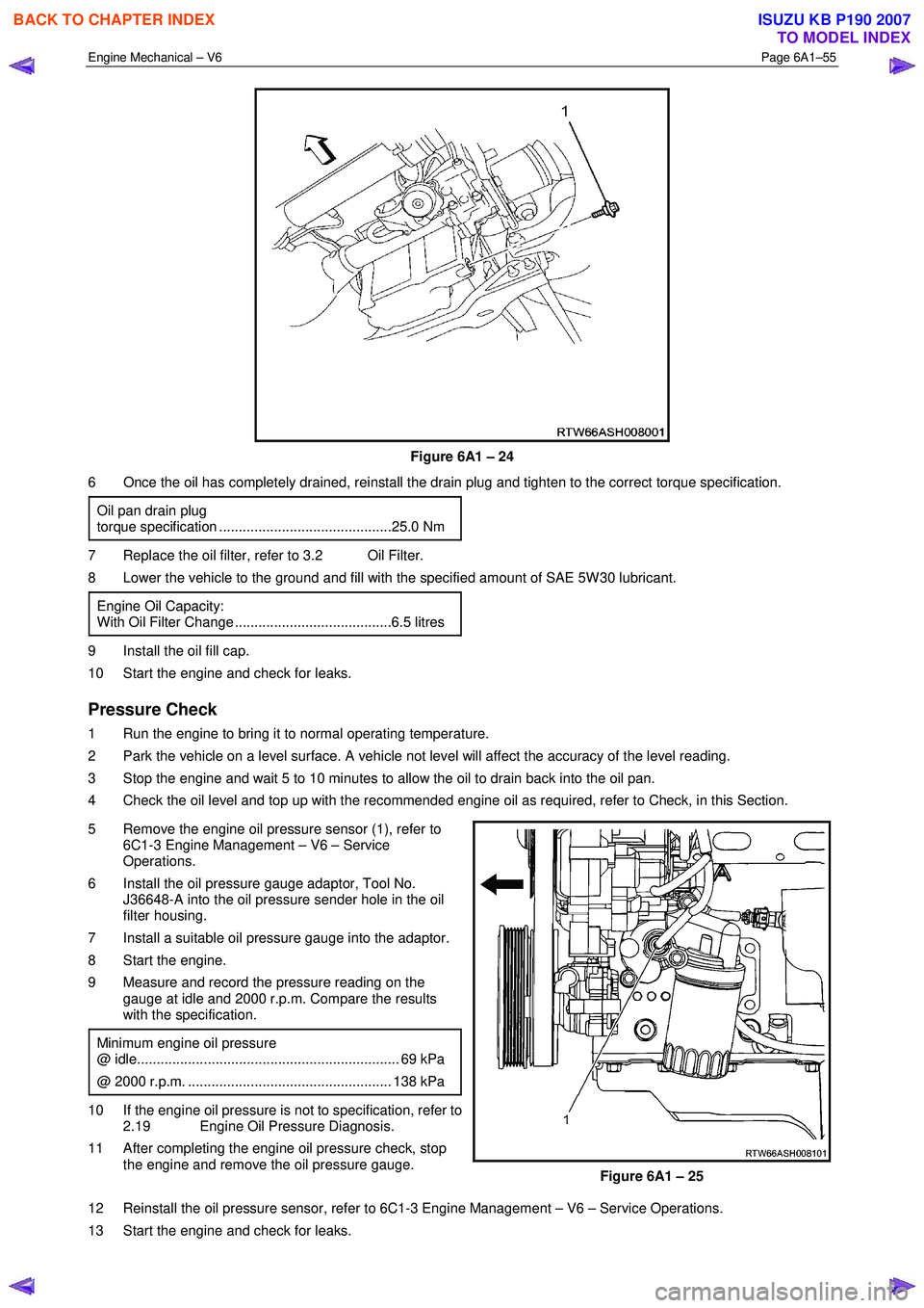
Figure 6A1 – 24
6 Once the oil has completely drained, reinstall the drain plug and tighten to the correct torque specification.
Oil pan drain plug
torque specification ............................................25.0 Nm
7 Replace the oil filter, refer to 3.2 Oil Filter.
8 Lower the vehicle to the ground and fill with the specified amount of SAE 5W 30 lubricant.
Engine Oil Capacity:
With Oil Filter Change ........................................6.5 litres
9 Install the oil fill cap.
10 Start the engine and check for leaks.
Pressure Check
1 Run the engine to bring it to normal operating temperature.
2 Park the vehicle on a level surface. A vehicle not level will affect the accuracy of the level reading.
3 Stop the engine and wait 5 to 10 minutes to allow the oil to drain back into the oil pan.
4 Check the oil level and top up with the recommended engine oil as required, refer to Check, in this Section.
5 Remove the engine oil pressure sensor (1), refer to 6C1-3 Engine Management – V6 – Service
Operations.
6 Install the oil pressure gauge adaptor, Tool No. J36648-A into the oil pressure sender hole in the oil
filter housing.
7 Install a suitable oil pressure gauge into the adaptor.
8 Start the engine.
9 Measure and record the pressure reading on the gauge at idle and 2000 r.p.m. Compare the results
with the specification.
Minimum engine oil pressure
@ idle................................................................... 69 kPa
@ 2000 r.p.m. .................................................... 138 kPa
10 If the engine oil pressure is not to specification, refer to 2.19 Engine Oil Pressure Diagnosis.
11 After completing the engine oil pressure check, stop the engine and remove the oil pressure gauge.
Figure 6A1 – 25
12 Reinstall the oil pressure sensor, refer to 6C1-3 Engine Management – V6 – Service Operations.
13 Start the engine and check for leaks.
BACK TO CHAPTER INDEX
TO MODEL INDEX
ISUZU KB P190 2007
Page 2544 of 6020
Engine Mechanical – V6 Page 6A1–65
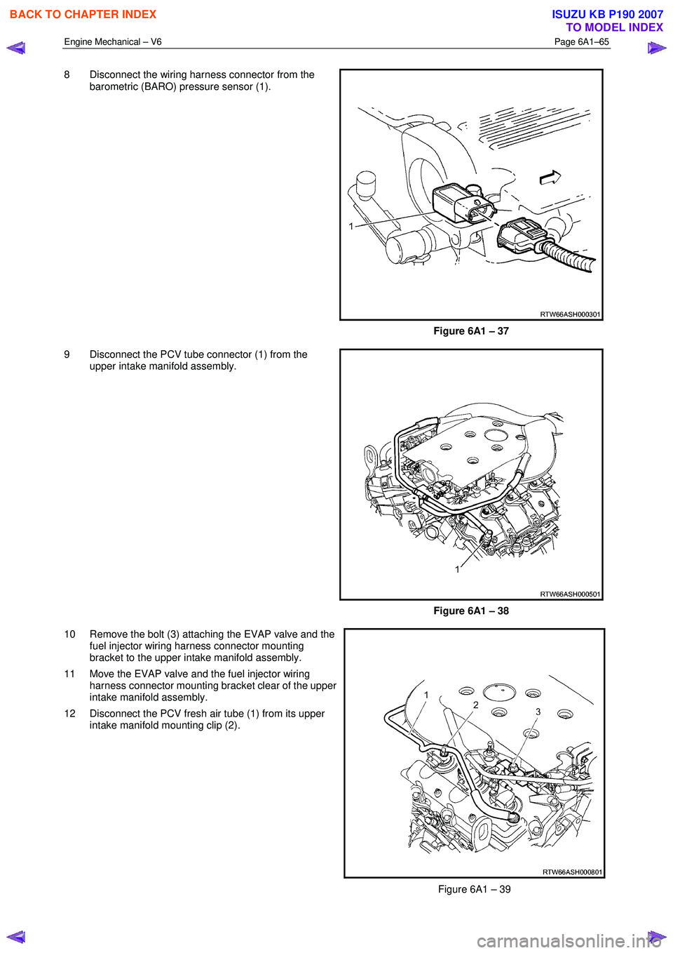
8 Disconnect the wiring harness connector from the
barometric (BARO) pressure sensor (1).
Figure 6A1 – 37
9 Disconnect the PCV tube connector (1) from the upper intake manifold assembly.
Figure 6A1 – 38
10 Remove the bolt (3) attaching the EVAP valve and the fuel injector wiring harness connector mounting
bracket to the upper intake manifold assembly.
11 Move the EVAP valve and the fuel injector wiring harness connector mounting bracket clear of the upper
intake manifold assembly.
12 Disconnect the PCV fresh air tube (1) from its upper intake manifold mounting clip (2).
Figure 6A1 – 39
BACK TO CHAPTER INDEX
TO MODEL INDEX
ISUZU KB P190 2007
Page 2550 of 6020
Engine Mechanical – V6 Page 6A1–71
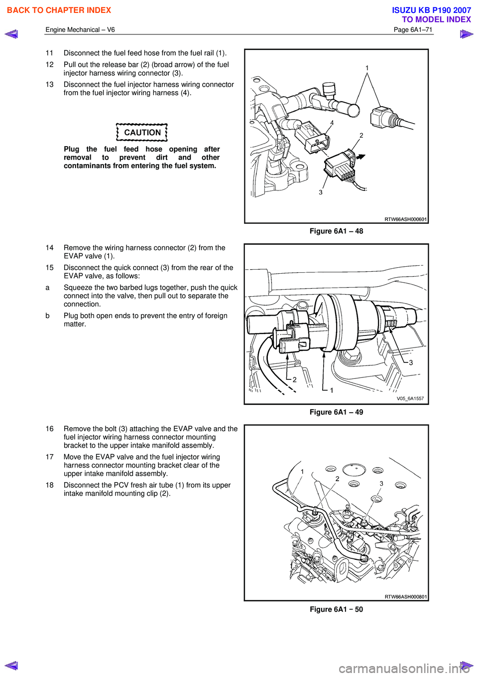
11 Disconnect the fuel feed hose from the fuel rail (1).
12 Pull out the release bar (2) (broad arrow) of the fuel injector harness wiring connector (3).
13 Disconnect the fuel injector harness wiring connector from the fuel injector wiring harness (4).
Plug the fuel feed hose opening after
removal to prevent dirt and other
contaminants from entering the fuel system.
Figure 6A1 – 48
14 Remove the wiring harness connector (2) from the EVAP valve (1).
15 Disconnect the quick connect (3) from the rear of the EVAP valve, as follows:
a Squeeze the two barbed lugs together, push the quick connect into the valve, then pull out to separate the
connection.
b Plug both open ends to prevent the entry of foreign matter.
Figure 6A1 – 49
16 Remove the bolt (3) attaching the EVAP valve and the fuel injector wiring harness connector mounting
bracket to the upper intake manifold assembly.
17 Move the EVAP valve and the fuel injector wiring harness connector mounting bracket clear of the
upper intake manifold assembly.
18 Disconnect the PCV fresh air tube (1) from its upper intake manifold mounting clip (2).
Figure 6A1 –
––
–
50
BACK TO CHAPTER INDEX
TO MODEL INDEX
ISUZU KB P190 2007
Page 2556 of 6020
Engine Mechanical – V6 Page 6A1–77
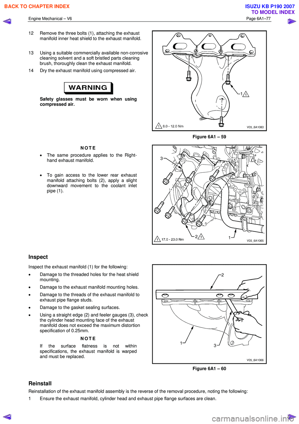
12 Remove the three bolts (1), attaching the exhaust
manifold inner heat shield to the exhaust manifold.
13 Using a suitable commercially available non-corrosive cleaning solvent and a soft bristled parts cleaning
brush, thoroughly clean the exhaust manifold.
14 Dry the exhaust manifold using compressed air.
Safety glasses must be worn when using
compressed air.
Figure 6A1 – 59
NOTE
• The same procedure applies to the Right-
hand exhaust manifold.
• To gain access to the lower rear exhaust
manifold attaching bolts (2), apply a slight
downward movement to the coolant inlet
pipe (1).
Inspect
Inspect the exhaust manifold (1) for the following:
• Damage to the threaded holes for the heat shield
mounting.
• Damage to the exhaust manifold mounting holes.
• Damage to the threads of the exhaust manifold to
exhaust pipe flange studs.
• Damage to the gasket sealing surfaces.
• Using a straight edge (2) and feeler gauges (3), check
the cylinder head mounting face of the exhaust
manifold does not exceed the maximum distortion
specification of 0.25mm.
NOTE
If the surface flatness is not within
specifications, the exhaust manifold is warped
and must be replaced.
Figure 6A1 – 60
Reinstall
Reinstallation of the exhaust manifold assembly is the reverse of the removal procedure, noting the following:
1 Ensure the exhaust manifold, cylinder head and exhaust pipe flange surfaces are clean.
BACK TO CHAPTER INDEX
TO MODEL INDEX
ISUZU KB P190 2007
Page 2557 of 6020

Engine Mechanical – V6 Page 6A1–78
2 Position a new exhaust manifold gasket onto the exhaust manifold.
3 Apply a 5 mm bead of Loctite 272 thread sealant (or equivalent) to the threads of the exhaust manifold attaching bolts.
4 Install the bolts into the exhaust manifold. This will prevent the gasket from falling off the manifold.
5 Manoeuvre the exhaust manifold into position and install the exhaust manifold attaching bolts.
6 From underneath the vehicle install the exhaust manifold to exhaust pipe flange nuts.
7 Tighten the exhaust manifold attaching bolts to the correct torque specification.
NOTE
When tightening the exhaust manifold to cylinder
head attaching bolts, begin with the centre bolts,
then alternate from side to side to the outer bolts.
Exhaust manifold to cylinder head
attaching bolt torque specification ...........17.0 – 23.0 Nm
8 Apply an anti seize compound such as Caltex Kopr-Kote (or equivalent) to the cleaned heat shield bolt threads. Install the heat shield attaching bolts and tighten to the correct torque specification.
Exhaust manifold heat shield attaching
bolt torque specification ............................8.0 – 12.0 Nm
9 For the right-hand side, install the battery harness ground cable attaching nut through the ground terminal and lower coolant tube mounting lug, and tighten to the correct torque specification.
Battery harness ground terminal
attaching nut torque specification.......................13.0 Nm
BACK TO CHAPTER INDEX
TO MODEL INDEX
ISUZU KB P190 2007
Page 2566 of 6020

Engine Mechanical – V6 Page 6A1–87
3.14 Crankshaft Front Seal
Replace
1 Remove the crankshaft balancer assembly, refer to 3.13 Crankshaft Balancer Assembly.
2 Using a flat bladed tool (2) or seal remover, Tool No. E-308, carefully remove the crankshaft front seal (1)
from the front cover.
Figure 6A1 – 81
3 Using crankshaft front seal installer, Tool No. J-29184 (2) and a suitable hammer, install a new crankshaft
front seal (1) until fully seated against the front cover
housing.
4 Install the crankshaft balancer assembly, refer to 3.13 Crankshaft Balancer Assembly.
CAUTION
Do not lubricate the crankshaft front oil seal
or crankshaft balancer sealing surfaces. The
crankshaft balancer is installed into a dry
seal.
Figure 6A1 – 82
3.15 Front Cover Assembly
Remove
1 Drain the engine coolant, refer to 6B1_Engine Cooling.
2 Remove the water outlet pipe and coolant pump assembly, refer to 6B1_ Engine Cooling:
3 Remove the camshaft covers, refer to 3.12 Camshaft Cover.
4 Remove the crankshaft balancer assembly, refer to 3.13 Crankshaft Balancer Assembly.
5 Disconnect the purge vent hose from the water outlet pipe.
NOTE
Do not disconnect the power steering pipes or
drain the power steering fluid.
6 Remove the power steering pump reservoir mounting bracket, refer to 3.8 Power Steering Pump Bracket.
7 Remove the camshaft position sensor, refer to 6C1-3 Engine Management – V6 – Service Operations.
BACK TO CHAPTER INDEX
TO MODEL INDEX
ISUZU KB P190 2007