4JH1 ISUZU KB P190 2007 Workshop User Guide
[x] Cancel search | Manufacturer: ISUZU, Model Year: 2007, Model line: KB P190, Model: ISUZU KB P190 2007Pages: 6020, PDF Size: 70.23 MB
Page 72 of 6020
1-38 HEATER AND AIR CONDITIONING
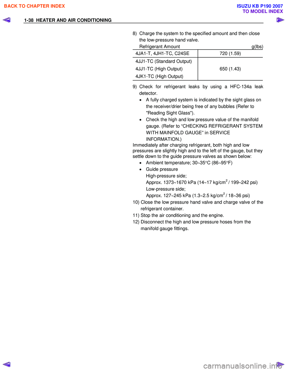
8) Charge the system to the specified amount and then close the low-pressure hand valve.
Refrigerant Amount g(lbs)
4JA1-T, 4JH1-TC, C24SE 720 (1.59)
4JJ1-TC (Standard Output)
4JJ1-TC (High Output)
4JK1-TC (High Output)
650 (1.43)
9) Check for refrigerant leaks by using a HFC-134a leak detector.
• A fully charged system is indicated by the sight glass on
the receiver/drier being free of any bubbles (Refer to
"Reading Sight Glass").
• Check the high and low pressure value of the manifold
gauge. (Refer to “CHECKING REFRIGERANT SYSTEM
W ITH MAINFOLD GAUGE” in SERVICE
INFORMATION.)
Immediately after charging refrigerant, both high and low
pressures are slightly high and to the left of the gauge, but they
settle down to the guide pressure valves as shown below:
• Ambient temperature; 30 ∼35 °C (86 ∼95 °F)
• Guide pressure
High-pressure side;
Approx. 1373 ∼1670 kPa (14 ∼17 kg/cm
2 / 199 ∼242 psi)
Low-pressure side;
Approx. 127 ∼245 kPa (1.3 ∼2.5 kg/cm
2 / 18 ∼36 psi)
10) Close the low pressure hand valve and charge valve of the refrigerant container.
11) Stop the air conditioning and the engine.
12) Disconnect the high and low pressure hoses from the manifold gauge fittings.
BACK TO CHAPTER INDEX
TO MODEL INDEX
ISUZU KB P190 2007
Page 74 of 6020
1-40 HEATER AND AIR CONDITIONING
CONDENSER
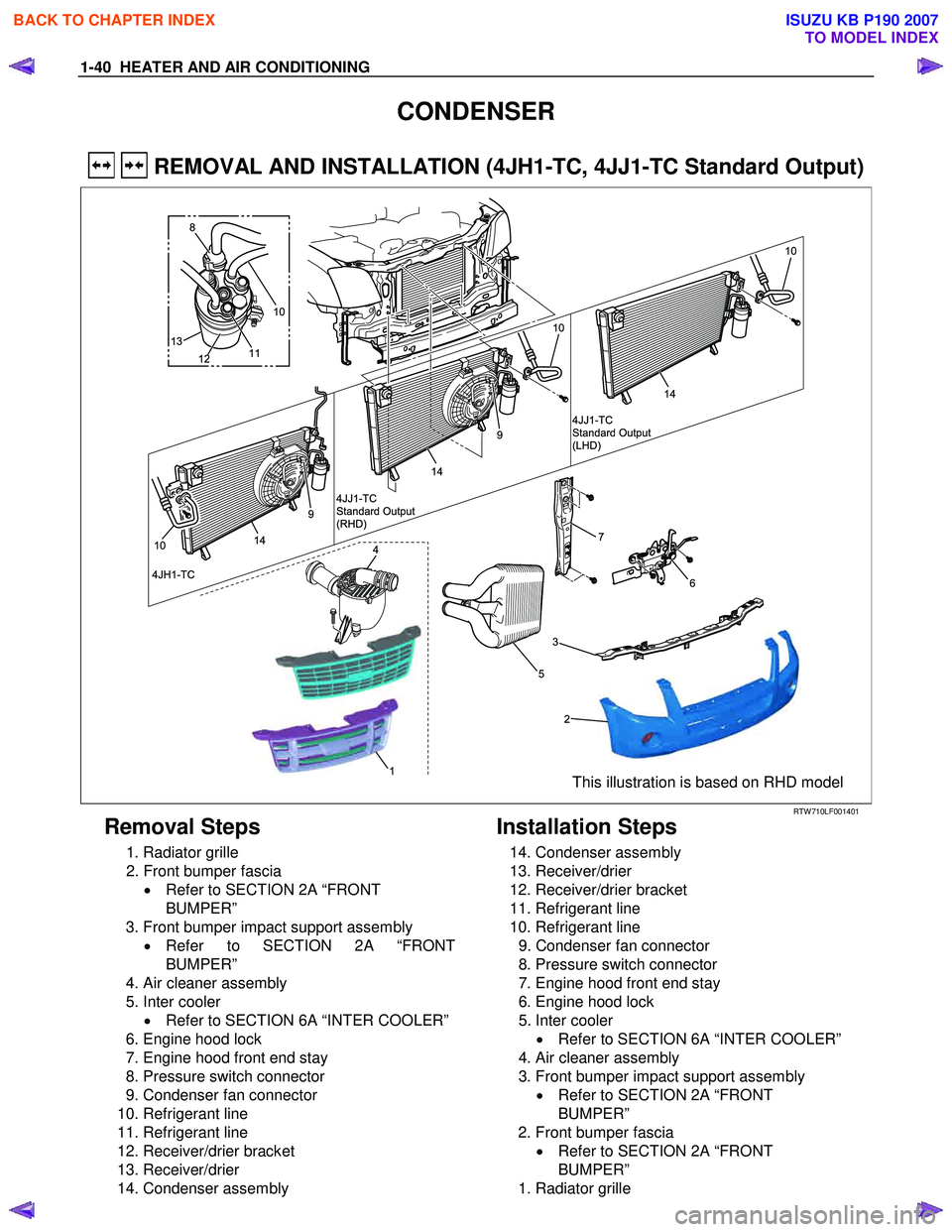
REMOVAL AND INSTALLATION (4JH1-TC, 4JJ1-TC Standard Output)
13
12
8
10
11
14
10
9
6
7
5
2
3
1
41410
4JH1-TC 4JJ1-TC
Standard Output
(RHD)
14
10
4JJ1-TC
Standard Output
(LHD)
9
This illustration is based on RHD model
RTW 710LF001401
Removal Steps
1. Radiator grille
2. Front bumper fascia • Refer to SECTION 2A “FRONT
BUMPER”
3. Front bumper impact support assembly • Refer to SECTION 2A “FRONT
BUMPER”
4. Air cleaner assembly
5. Inter cooler • Refer to SECTION 6A “INTER COOLER”
6. Engine hood lock
7. Engine hood front end stay
8. Pressure switch connector
9. Condenser fan connector
10. Refrigerant line
11. Refrigerant line
12. Receiver/drier bracket
13. Receiver/drier
14. Condenser assembly
Installation Steps
14. Condenser assembly
13. Receiver/drier
12. Receiver/drier bracket
11. Refrigerant line
10. Refrigerant line
9. Condenser fan connector
8. Pressure switch connector
7. Engine hood front end stay
6. Engine hood lock
5. Inter cooler • Refer to SECTION 6A “INTER COOLER”
4. Air cleaner assembly
3. Front bumper impact support assembly • Refer to SECTION 2A “FRONT
BUMPER”
2. Front bumper fascia • Refer to SECTION 2A “FRONT
BUMPER”
1. Radiator grille
BACK TO CHAPTER INDEX
TO MODEL INDEX
ISUZU KB P190 2007
Page 79 of 6020
HEATER AND AIR CONDITIONING 1-45
COMPRESSOR
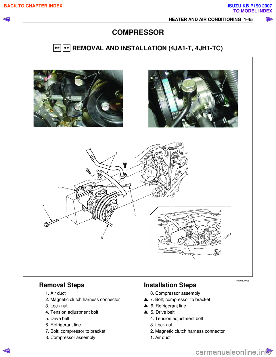
REMOVAL AND INSTALLATION (4JA1-T, 4JH1-TC)
852R300006
Removal Steps
1. Air duct
2. Magnetic clutch harness connector
3. Lock nut
4. Tension adjustment bolt
5. Drive belt
6. Refrigerant line
7. Bolt; compressor to bracket
8. Compressor assembly
Installation Steps
8. Compressor assembly
7. Bolt; compressor to bracket
6. Refrigerant line
5. Drive belt
4. Tension adjustment bolt
3. Lock nut
2. Magnetic clutch harness connector
1. Air duct
BACK TO CHAPTER INDEX
TO MODEL INDEX
ISUZU KB P190 2007
Page 116 of 6020

1-82 HEATER AND AIR CONDITIONING
RTW 710SH000801
Fan switch and A/C switch
Check for continuity between fan switch and A/C switch side
connector terminals.
(A/C (4JA1-T, 4JJ1-TC Standard Output, 4JJ1-TC High
Output, 4JK1-TC High Output))
B-13 B-57
Terminal No.
SW .
position
1234 5 6 2 3156
OFF
1
2
3
(FAN SW .)
4
OFF (A/C SW .)ON
RUW 710SH000501
(A/C (4JH1-TC, C24SE)).
B-13 B-57
Terminal
No.
SW .
position
123 4 5 6156
OFF
1
2
3
(FAN SW .)
4
OFF (A/C SW .)ON
D08R300070
(Cooler)
B-13 B-57
Terminal
No.
SW .
position
1 2 3 4 5 6 2 3 10 11
OFF
1
2
3
(FAN SW .)
4
OFF (A/C SW .)ON
BACK TO CHAPTER INDEX
TO MODEL INDEX
ISUZU KB P190 2007
Page 133 of 6020

HEATER AND AIR CONDITIONING 1-99
4JH1 – TC
RTW 710XF000301
BACK TO CHAPTER INDEX
TO MODEL INDEX
ISUZU KB P190 2007
Page 134 of 6020
1-100 HEATER AND AIR CONDITIONING
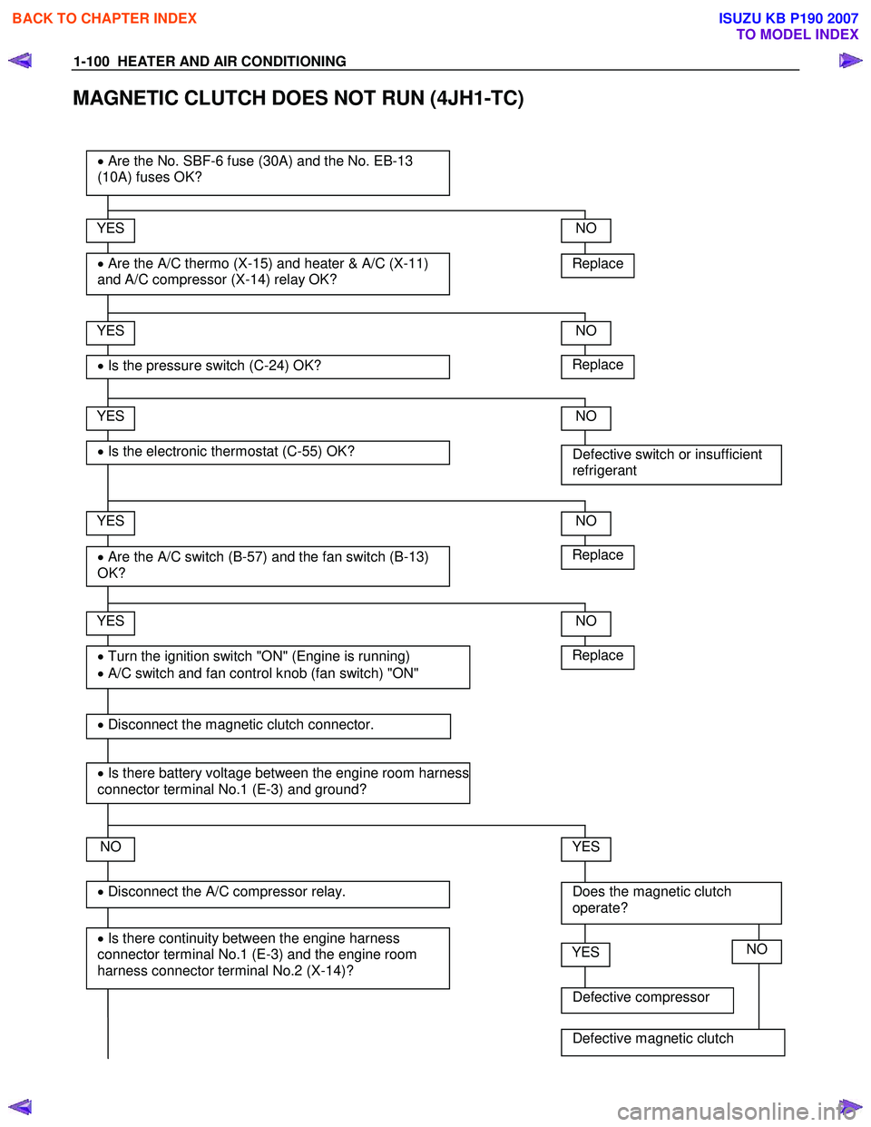
MAGNETIC CLUTCH DOES NOT RUN (4JH1-TC)
Replace
YES
• Are the A/C thermo (X-15) and heater & A/C (X-11)
and A/C compressor (X-14) relay OK?
• Are the No. SBF-6 fuse (30A) and the No. EB-13
(10A) fuses OK?
YES
• Is the pressure switch (C-24) OK?
YES
• Are the A/C switch (B-57) and the fan switch (B-13)
OK?
NO
YES
• Is there continuity between the engine harness
connector terminal No.1 (E-3) and the engine room
harness connector terminal No.2 (X-14)?
• Disconnect the A/C compressor relay.
• Turn the ignition switch "ON" (Engine is running)
• A/C switch and fan control knob (fan switch) "ON"
NO
Replace
NO
Defective switch or insufficient
refrigerant
NO
NO
Does the magnetic clutch
operate?
YES
Replace
• Disconnect the magnetic clutch connector.
• Is there battery voltage between the engine room harness
connector terminal No.1 (E-3) and ground?
Defective compressor
YESNO
Defective magnetic clutch
• Is the electronic thermostat (C-55) OK?
YES
Replace
NO
BACK TO CHAPTER INDEX
TO MODEL INDEX
ISUZU KB P190 2007
Page 262 of 6020

POWER-ASSISTED STEERING SYSTEM 3B-1
SECTION 3B
POWER-ASSISTED STEERING SYSTEM
TABLE OF CONTENTS
PAGE
General Description......................................................................................................... 3B – 4
Power Steering System Test .......................................................................................... 3B – 7
Maintenance .................................................................................................................... . 3B – 8
Fluid Level .................................................................................................................... .... 3B – 8
Bleeding The Power Steering System ........................................................................... 3B – 8
Bleeding Procedure ......................................................................................................... 3B – 8
Flushing The Power Steering System............................................................................ 3B – 8
Steering Wheel Free Play Inspection ............................................................................. 3B – 9
Front End Alignment Inspection and Adjustment......................................................... 3B – 9
Special Tools .................................................................................................................. . 3B – 10
Power Steering Unit......................................................................................................... 3B – 11
Power Steering Unit and Associated Parts............................................................... 3B – 11
Removal ....................................................................................................................... 3B – 11
Installation ................................................................................................................... 3B – 12
Power Steering Unit Disassembled View.................................................................. 3B – 13
Disassembly ................................................................................................................ 3B – 14
Inspection and Repair................................................................................................. 3B – 14
Reassembly ................................................................................................................. 3B – 14
Main Data and Specifications .................................................................................... 3B – 15
Special Tools ............................................................................................................... 3B – 16
Power Steering Pump...................................................................................................... 3B – 17
Power Steering Pump and Associated Parts (4JH1-TC, 4JA1-T) ............................ 3B – 17
Removal ....................................................................................................................... 3B – 17
Installation ................................................................................................................... 3B – 17
Power Steering Pump Disassembled View .............................................................. 3B – 18
Disassembly ................................................................................................................ 3B – 19
Inspection and Repair................................................................................................. 3B – 19
Reassembly ................................................................................................................. 3B – 20
Main Data and Specifications .................................................................................... 3B – 20
BACK TO CHAPTER INDEX
TO MODEL INDEX
ISUZU KB P190 2007
Page 278 of 6020

POWER-ASSISTED STEERING SYSTEM 3B-17
Power Steering Pump (4JH1-TC, 4JA1-T)
Power Steering Pump and Associated Parts
RTW 53BMF000401
Legend (1) Pump Assembly
(2) Suction Hose
(3) Flexible Hose
(4) Bolt
(5) Bracket
Removal
1. Remove the drive belt.
2. Remove the pulley
3. Place a drain pan below the pump.
4. Disconnect the suction hose.
5. Disconnect the flexible hose.
6. Remove the power steering fixing bolt and remove the pump assembly.
Installation
1. Install the pump assembly to the pump braket,
tighten the fixing bolt to the specified torque.
Torque: 40 N·m (4.1 kgf·m/30 lb·ft)
2. Install the flexible hose.
Tighten the nut to specified torque.
Torque: 20 N·m (2.0 kgf·m/14 lb·ft)
3. Install the pulley and tighten the bolt to the specified torque.
Torque: 28 N·m (2.9 kgf·m/21 lb·ft)
4. Install the drive belt.
5. Connect the suction hose, then fill and bleed system.
Refer to Bleeding the Power Steering System in this section.
BACK TO CHAPTER INDEX
TO MODEL INDEX
ISUZU KB P190 2007
Page 282 of 6020
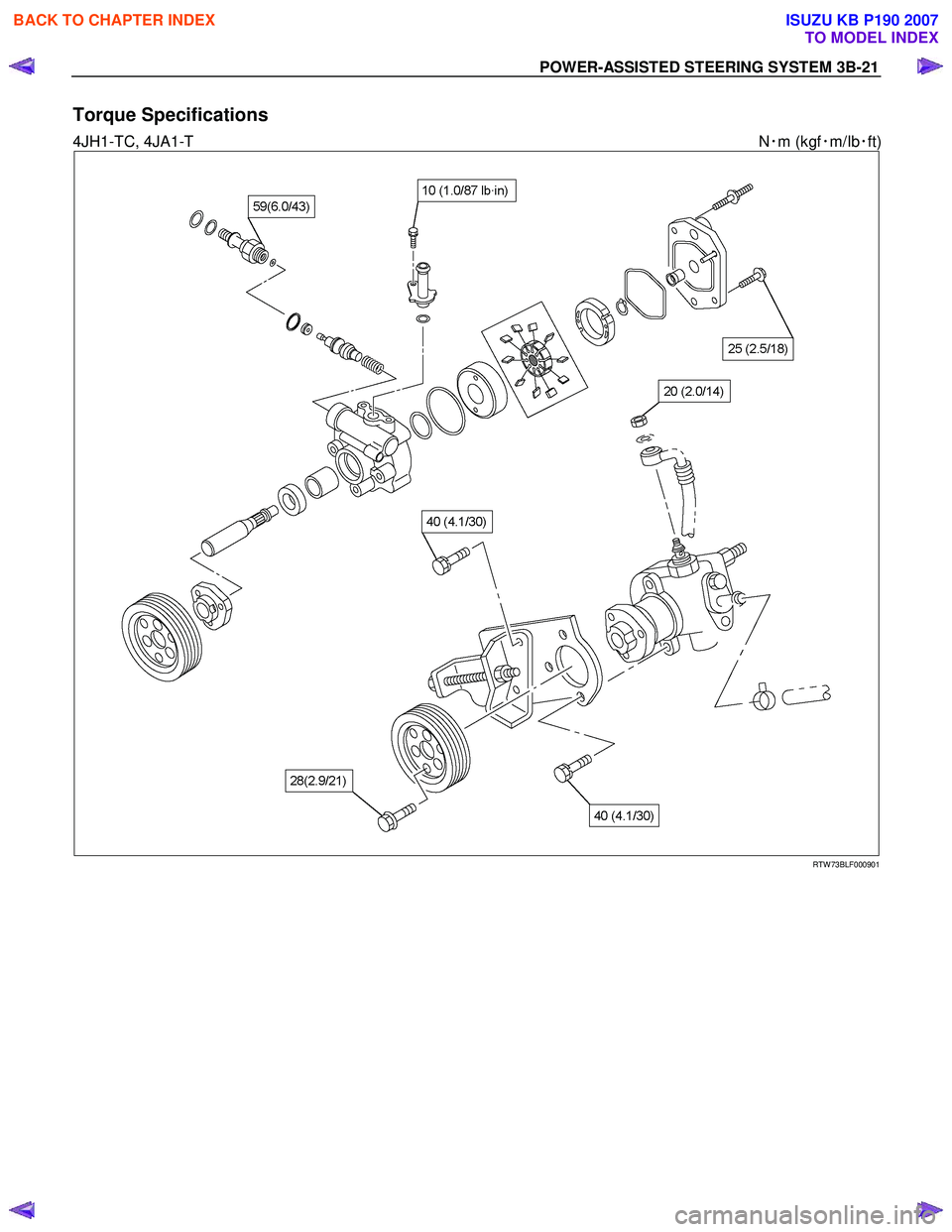
POWER-ASSISTED STEERING SYSTEM 3B-21
Torque Specifications
4JH1-TC, 4JA1-T N・m (kgf ・m/Ib ・ft)
RTW 73BLF000901
BACK TO CHAPTER INDEX
TO MODEL INDEX
ISUZU KB P190 2007
Page 421 of 6020

PROPELLER SHAFT 4A-5
4 ×4 Model
Engine Model 4JA1-T(L) 4JA1-TC 4JH1-TC
Transmission Type 5M/T (MUA) 5M/T (MUA) 4A/T
W heel Base Long Long Extra Long Long
Front Suspension
Rear Axle φ220mm ← ← ←
Type OBS ← ← ←
Outside Diameter mm 75 68.9 68.9 63.5
(in) (2.95) (2.71) (2.71) (2.50)
Inside Diameter mm 71.8 64.9 64.9 60.3
(in) (2.83) (2.56) (2.56) (2.37)
Length 1st(L1) mm 469.5 468.5 616.5 402.5
(in) (18.48) (18.44) (24.27) (15.85)
2nd(L2) mm 801 801 801 801
(in) (31.54) (31.54) (31.54) (31.54)
Spline Major mm 29.89 29.89 29.89 29.89
Diameter (in) (1.18) (1.18) (1.18) (1.18)
Fix Bolt Size M10 M10 M10 M10
* OBS - Outboard Slip (Spline Engagement To T/M)
4 ×4 Model
Engine Model C24SE HFV6
Transmission Type 5M/T
(MUA) 5M/T (AR-5)
4A/T
W heel Base Long Long Extra Long Long
Front Suspension
Rear Axle φ220mm
← ← ←
Type OBS
← ← ←
Outside Diameter mm 63.5 68.9 68.9 75
(in) (2.50) (2.71) (2.71) (2.95)
Inside Diameter mm 60.3 64.9 64.9 71.8
(in) (2.37) (2.56) (2.56) (2.83)
Length 1st(L1) mm 495.5 476.5 624.5 484.5
(in) (19.51) (18.75) (24.59) (19.07)
2nd(L2) mm 801 801 801 801
(in) (31.54) (31.54) (31.54) (31.54)
Spline Major mm 29.89 29.89 29.89 29.89
Diameter (in) (1.18) (1.18) (1.18) (1.18)
Fix Bolt Size M10 M10 M10 M10
* OBS - Outboard Slip (Spline Engagement To T/M)
BACK TO CHAPTER INDEX
TO MODEL INDEX
ISUZU KB P190 2007