lock ISUZU KB P190 2007 Workshop Repair Manual
[x] Cancel search | Manufacturer: ISUZU, Model Year: 2007, Model line: KB P190, Model: ISUZU KB P190 2007Pages: 6020, PDF Size: 70.23 MB
Page 1496 of 6020
6A-136 ENGINE MECHANICAL (4JK1/4JJ1)
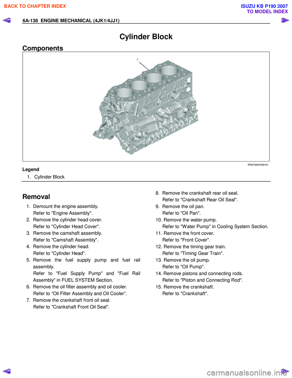
Cylinder Block
Components
RTW 76ASF000101
Legend
1. Cylinder Block
Removal
1. Demount the engine assembly.
Refer to "Engine Assembly".
2. Remove the cylinder head cover.
Refer to "Cylinder Head Cover".
3. Remove the camshaft assembly.
Refer to "Camshaft Assembly".
4. Remove the cylinder head.
Refer to "Cylinder Head".
5. Remove the fuel supply pump and fuel rail assembly.
Refer to "Fuel Supply Pump" and "Fuel Rail Assembly" in FUEL SYSTEM Section.
6. Remove the oil filter assembly and oil cooler.
Refer to “Oil Filter Assembly and Oil Cooler”.
7. Remove the crankshaft front oil seal.
Refer to "Crankshaft Front Oil Seal".
8. Remove the crankshaft rear oil seal.
Refer to "Crankshaft Rear Oil Seal".
9. Remove the oil pan.
Refer to "Oil Pan".
10. Remove the water pump.
Refer to "W ater Pump" in Cooling System Section.
11. Remove the front cover.
Refer to "Front Cover".
12. Remove the timing gear train.
Refer to "Timing Gear Train".
13. Remove the oil pump.
Refer to "Oil Pump".
14. Remove pistons and connecting rods.
Refer to "Piston and Connecting Rod".
15. Remove the crankshaft.
Refer to "Crankshaft".
BACK TO CHAPTER INDEX
TO MODEL INDEX
ISUZU KB P190 2007
Page 1497 of 6020
ENGINE MECHANICAL (4JK1/4JJ1) 6A-137
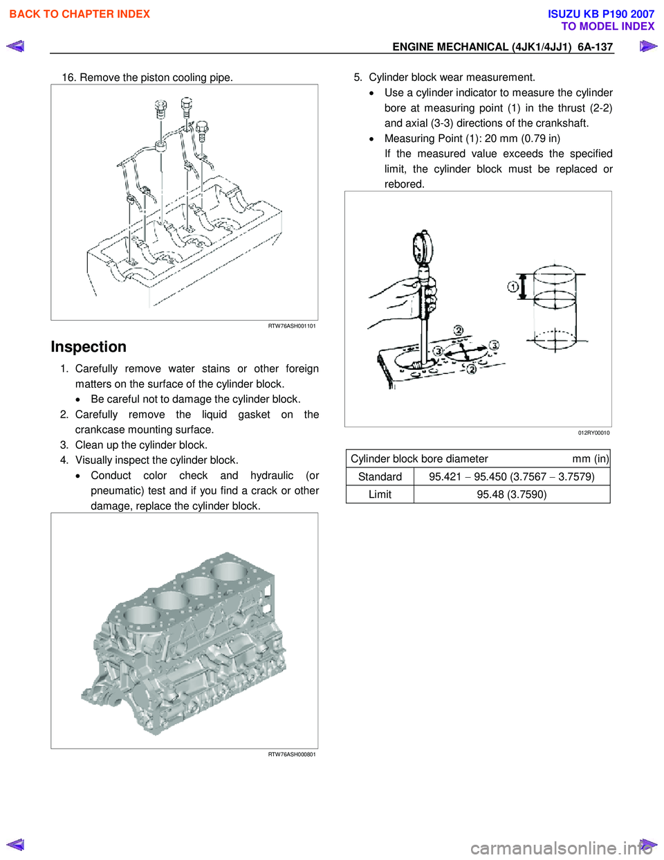
16. Remove the piston cooling pipe.
RTW 76ASH001101
Inspection
1. Carefully remove water stains or other foreign
matters on the surface of the cylinder block.
• Be careful not to damage the cylinder block.
2. Carefully remove the liquid gasket on the crankcase mounting surface.
3. Clean up the cylinder block.
4. Visually inspect the cylinder block. • Conduct color check and hydraulic (o
r
pneumatic) test and if you find a crack or other
damage, replace the cylinder block.
RTW 76ASH000801
5. Cylinder block wear measurement.
• Use a cylinder indicator to measure the cylinde
r
bore at measuring point (1) in the thrust (2-2)
and axial (3-3) directions of the crankshaft.
• Measuring Point (1): 20 mm (0.79 in)
If the measured value exceeds the specified limit, the cylinder block must be replaced o
r
rebored.
012RY00010
Cylinder block bore diameter mm (in)
Standard 95.421 − 95.450 (3.7567 − 3.7579)
Limit 95.48 (3.7590)
BACK TO CHAPTER INDEX
TO MODEL INDEX
ISUZU KB P190 2007
Page 1498 of 6020
6A-138 ENGINE MECHANICAL (4JK1/4JJ1)
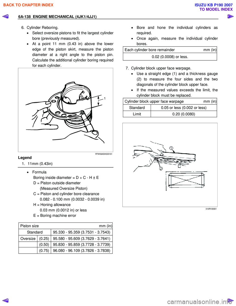
6. Cylinder Reboring.
• Select oversize pistons to fit the largest cylinde
r
bore (previously measured).
• At a point 11 mm (0.43 in) above the lowe
r
edge of the piston skirt, measure the piston
diameter at a right angle to the piston pin.
Calculate the additional cylinder boring required
for each cylinder.
RTW 56ASH023101
Legend
1. 11mm (0.43in)
• Formula
Boring inside diameter = D + C - H ± E
D = Piston outside diameter (Measured Oversize Piston)
C = Piston and cylinder bore clearance 0.082 - 0.100 mm (0.0032 - 0.0039 in)
H = Honing allowance 0.03 mm (0.0012 in) or less
E = Boring machine error
Piston size mm (in)
Standard 95.330 - 95.359 (3.7531 - 3.7543)
Oversize (0.25) 95.580 - 95.609 (3.7629 - 3.7641)
(0.50) 95.830 - 95.859 (3.7728 - 3.7739)
(0.75) 96.080 - 96.109 (3.7826 - 3.7838)
• Bore and hone the individual cylinders as
required.
• Once again, measure the individual cylinde
r
bores.
Each cylinder bore remainder mm (in)
0.02 (0.0008) or less.
7. Cylinder block upper face warpage.
• Use a straight edge (1) and a thickness gauge
(2) to measure the four sides and the two
diagonals of the cylinder block upper face.
• If the measured values exceeds the limit, the
cylinder block must be replaced.
Cylinder block upper face warpage mm (in)
Standard 0.05 or less (0.002 or less)
Limit 0.20 (0.0080)
012R100001
BACK TO CHAPTER INDEX
TO MODEL INDEX
ISUZU KB P190 2007
Page 1499 of 6020
ENGINE MECHANICAL (4JK1/4JJ1) 6A-139
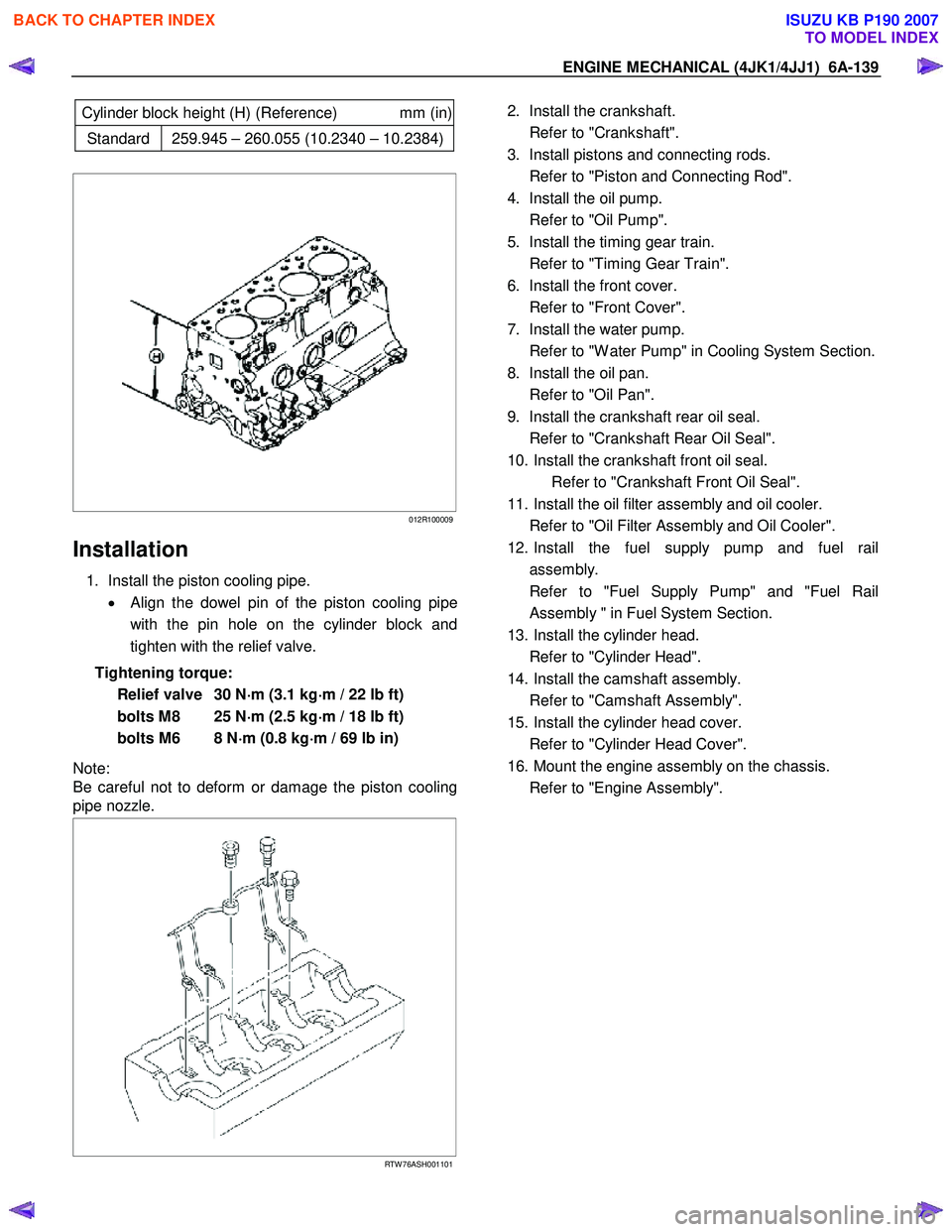
Cylinder block height (H) (Reference) mm (in)
Standard 259.945 – 260.055 (10.2340 – 10.2384)
012R100009
Installation
1. Install the piston cooling pipe.
• Align the dowel pin of the piston cooling pipe
with the pin hole on the cylinder block and
tighten with the relief valve.
Tightening torque: Relief valve 30 N ⋅
⋅⋅
⋅
m (3.1 kg ⋅
⋅⋅
⋅
m / 22 lb ft)
bolts M8 25 N ⋅
⋅⋅
⋅
m (2.5 kg ⋅
⋅⋅
⋅
m / 18 lb ft)
bolts M6 8 N ⋅
⋅⋅
⋅
m (0.8 kg ⋅
⋅⋅
⋅
m / 69 lb in)
Note:
Be careful not to deform or damage the piston cooling
pipe nozzle.
RTW 76ASH001101
2. Install the crankshaft.
Refer to "Crankshaft".
3. Install pistons and connecting rods.
Refer to "Piston and Connecting Rod".
4. Install the oil pump.
Refer to "Oil Pump".
5. Install the timing gear train.
Refer to "Timing Gear Train".
6. Install the front cover.
Refer to "Front Cover".
7. Install the water pump.
Refer to "W ater Pump" in Cooling System Section.
8. Install the oil pan.
Refer to "Oil Pan".
9. Install the crankshaft rear oil seal.
Refer to "Crankshaft Rear Oil Seal".
10. Install the crankshaft front oil seal. Refer to "Crankshaft Front Oil Seal".
11. Install the oil filter assembly and oil cooler.
Refer to "Oil Filter Assembly and Oil Cooler".
12. Install the fuel supply pump and fuel rail assembly.
Refer to "Fuel Supply Pump" and "Fuel Rail Assembly " in Fuel System Section.
13. Install the cylinder head.
Refer to "Cylinder Head".
14. Install the camshaft assembly.
Refer to "Camshaft Assembly".
15. Install the cylinder head cover.
Refer to "Cylinder Head Cover".
16. Mount the engine assembly on the chassis.
Refer to "Engine Assembly".
BACK TO CHAPTER INDEX
TO MODEL INDEX
ISUZU KB P190 2007
Page 1507 of 6020
ENGINE MECHANICAL (4JK1/4JJ1) 6A-147
Reassembly
1. Install the gasket on the element.
2. Install the element.
3. Tighten the element fixing nut using the specified torque.
Tightening torque: 25 N ⋅
⋅⋅
⋅
m (2.5 kg ⋅
⋅⋅
⋅
m / 18 lb ft)
Installation
1. Install the oil filter and cooler.
• Install the O-ring on the oil filter and cooler,
apply grease.
•
Apply the liquid gasket and mount within 5
minutes. Apply liquid gasket (ThreeBond TB-
1207C or equivalent) to the flange surface
groove (cylinder block). Bead diameter must
be between 2 and 3 mm (0.079 and 0.118 in).
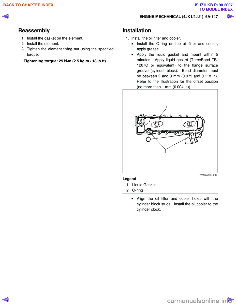
Refer to the illustration for the offset position
(no more than 1 mm (0.004 in)).
RTW 56ASH013101
Legend
1. Liquid Gasket
2. O-ring
• Align the oil filter and cooler holes with the
cylinder block studs. Install the oil cooler to the
cylinder clock.
BACK TO CHAPTER INDEX
TO MODEL INDEX
ISUZU KB P190 2007
Page 1518 of 6020
6A-158 ENGINE MECHANICAL (4JK1/4JJ1)
Reassembly
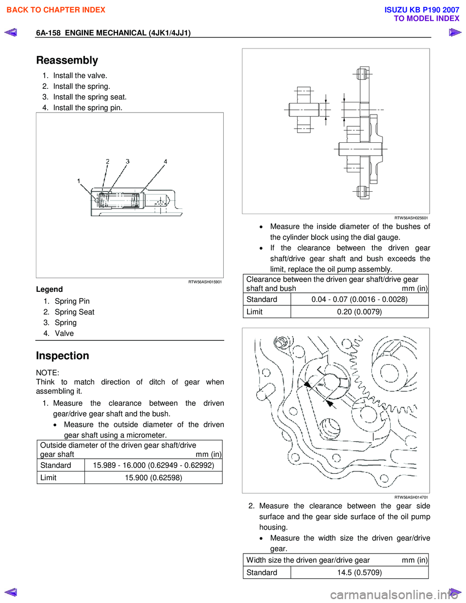
1. Install the valve.
2. Install the spring.
3. Install the spring seat.
4. Install the spring pin.
RTW 56ASH015901
Legend
1. Spring Pin
2. Spring Seat
3. Spring
4. Valve
Inspection
NOTE:
Think to match direction of ditch of gear when
assembling it.
1. Measure the clearance between the driven gear/drive gear shaft and the bush.
• Measure the outside diameter of the driven
gear shaft using a micrometer.
Outside diameter of the driven gear shaft/drive
gear shaft mm (in)
Standard 15.989 - 16.000 (0.62949 - 0.62992)
Limit 15.900 (0.62598)
RTW 56ASH025601
• Measure the inside diameter of the bushes of
the cylinder block using the dial gauge.
• If the clearance between the driven gea
r
shaft/drive gear shaft and bush exceeds the
limit, replace the oil pump assembly.
Clearance between the driven gear shaft/drive gear
shaft and bush mm (in)
Standard 0.04 - 0.07 (0.0016 - 0.0028)
Limit 0.20 (0.0079)
RTW 56ASH014701
2. Measure the clearance between the gear side
surface and the gear side surface of the oil pump
housing.
• Measure the width size the driven gear/drive
gear.
W idth size the driven gear/drive gear mm (in)
Standard 14.5 (0.5709)
BACK TO CHAPTER INDEX
TO MODEL INDEX
ISUZU KB P190 2007
Page 1521 of 6020
ENGINE MECHANICAL (4JK1/4JJ1) 6A-161
Oil Pressure SW
Components
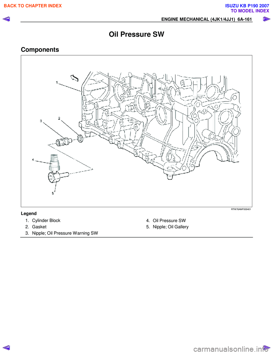
RTW 76AMF000401
Legend 1. Cylinder Block
2. Gasket
3. Nipple; Oil Pressure W arning SW 4. Oil Pressure SW
5. Nipple; Oil Gallery
BACK TO CHAPTER INDEX
TO MODEL INDEX
ISUZU KB P190 2007
Page 1537 of 6020
6B-14 ENGINE COOLING (4JK1/4JJ1)
Removal
1. Disconnect battery ground cable.
2. Loosen a drain plug to drain EC.
3. Disconnect oil cooler hose on automatic transmission (A/T).
4. Remove the engine cover.
5. Disconnect radiator inlet hose and outlet hose from the engine.
RTW 56BSH000301
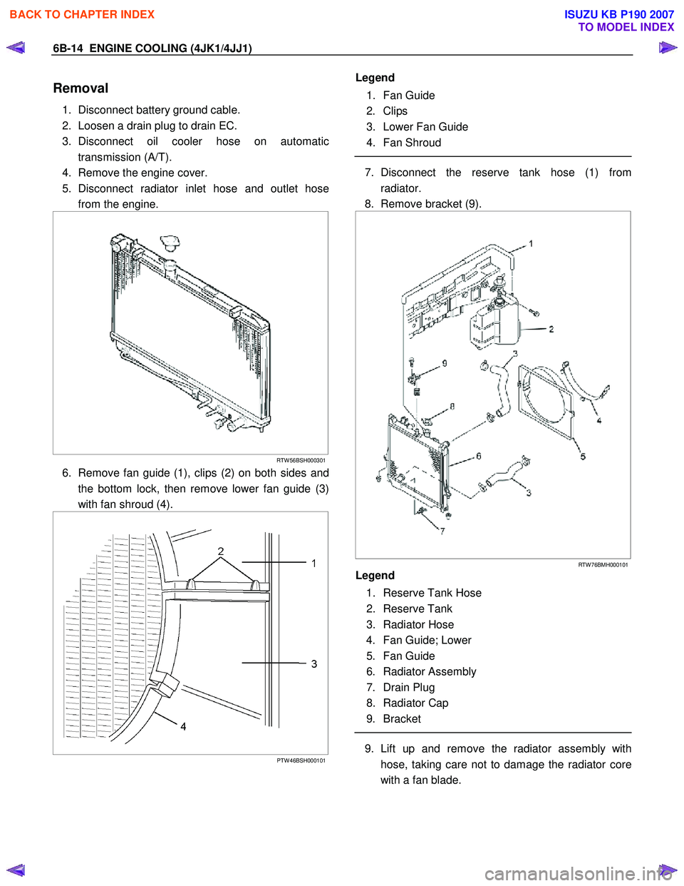
6. Remove fan guide (1), clips (2) on both sides and
the bottom lock, then remove lower fan guide (3)
with fan shroud (4).
PTW 46BSH000101
Legend
1. Fan Guide
2. Clips
3. Lower Fan Guide
4. Fan Shroud
7. Disconnect the reserve tank hose (1) from
radiator.
8. Remove bracket (9).
RTW 76BMH000101
Legend
1. Reserve Tank Hose
2. Reserve Tank
3. Radiator Hose
4. Fan Guide; Lower
5. Fan Guide
6. Radiator Assembly
7. Drain Plug
8. Radiator Cap
9. Bracket
9. Lift up and remove the radiator assembly with
hose, taking care not to damage the radiator core
with a fan blade.
BACK TO CHAPTER INDEX
TO MODEL INDEX
ISUZU KB P190 2007
Page 1548 of 6020

FUEL SYSTEM (4JK1/4JJ1) 6C-7
g. Check that the warning lamp in the meter is off.
2. Draining with drain plug in engine room. a. W ith the engine off, open the engine hood and loosen the drain plug (1) located on the left
hand side of the engine room. (3-4 turns)
b. Turn the starter switch to the “ON” position fo
r
10 seconds, and then turn the starter switch to
the “OFF” position for 10 seconds. Then, once
again turn the starter switch to the “ON”
position for 10 seconds.
c. Tighten the drain plug firmly.
d.
After starting the engine, check that there is no
fuel leakage from the drain plug. Also check
that the water separator indicator has turned
off.
RTW 76CSH001301
NOTE:
• If the water separator requires frequent draining,
have the fuel tank drained at your ISUZU/GM
Dealer.
• Be sure to stop the engine when draining the fuel
tank.
• Confirm that there are no combustible materials
under the drain hose, and use a receptacle to
catch the drained water.
Engine starting cautions
• Before starting the engine, turn the ignition switch
to the “ON” position. W ait 15 seconds. Return the
switch to the “LOCK” position. Repeat this
procedure 5 times.
• After starting the engine, allow it to idle for 10
minutes.
Fuel Pump Functional Check
1. Turn the starter switch to “ON” position.
2. Touch the under portion of the Fuel Tank by the hand as shown in the following figure within 12
seconds.
RTW 56CSH003501
Legend
1. Touch this area by the hand
3. Make sure a vibration by the Fuel Pump is
detected.
Fuel Pump stops within 12 seconds of turning the starter switch to the “ON” position.
W hen the check is repeated, return the starte
r
switch to the “LOCK” position for 10 – 15 seconds
and perform procedures 1 – 3.
WARNING: FUEL PUMP FUNCTIONAL CHECK
MUST BE CONDUCTED UNDER THE FOLLOWING
CONDITIONS TO AVOID INJURY.
•
••
•
APPLY THE PARKING BRAKE.
•
••
•
STOP THE ENGINE.
BACK TO CHAPTER INDEX
TO MODEL INDEX
ISUZU KB P190 2007
Page 1551 of 6020
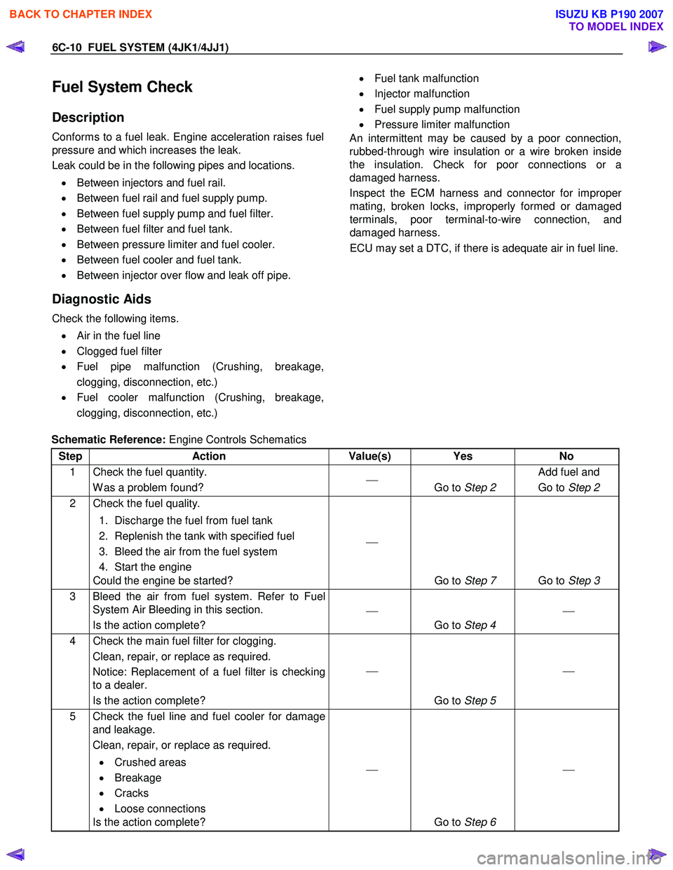
6C-10 FUEL SYSTEM (4JK1/4JJ1)
Fuel System Check
Description
Conforms to a fuel leak. Engine acceleration raises fuel
pressure and which increases the leak.
Leak could be in the following pipes and locations.
• Between injectors and fuel rail.
• Between fuel rail and fuel supply pump.
• Between fuel supply pump and fuel filter.
• Between fuel filter and fuel tank.
• Between pressure limiter and fuel cooler.
• Between fuel cooler and fuel tank.
• Between injector over flow and leak off pipe.
Diagnostic Aids
Check the following items.
• Air in the fuel line
• Clogged fuel filter
• Fuel pipe malfunction (Crushing, breakage,
clogging, disconnection, etc.)
• Fuel cooler malfunction (Crushing, breakage,
clogging, disconnection, etc.)
• Fuel tank malfunction
• Injector malfunction
• Fuel supply pump malfunction
• Pressure limiter malfunction
An intermittent may be caused by a poor connection,
rubbed-through wire insulation or a wire broken inside
the insulation. Check for poor connections or a
damaged harness.
Inspect the ECM harness and connector for imprope
r
mating, broken locks, improperly formed or damaged
terminals, poor terminal-to-wire connection, and
damaged harness.
ECU may set a DTC, if there is adequate air in fuel line.
Schematic Reference: Engine Controls Schematics
Step Action Value(s) Yes No
1 Check the fuel quantity. W as a problem found?
Go to Step 2 Add fuel and
Go to Step 2
2 Check the fuel quality.
1. Discharge the fuel from fuel tank
2. Replenish the tank with specified fuel
3. Bleed the air from the fuel system
4. Start the engine
Could the engine be started?
Go to Step 7 Go to Step 3
3 Bleed the air from fuel system. Refer to Fuel
System Air Bleeding in this section.
Is the action complete?
Go to Step 4
4 Check the main fuel filter for clogging.
Clean, repair, or replace as required.
Notice: Replacement of a fuel filter is checking
to a dealer.
Is the action complete?
Go to Step 5
5 Check the fuel line and fuel cooler for damage
and leakage.
Clean, repair, or replace as required.
• Crushed areas
• Breakage
• Cracks
• Loose connections
Is the action complete?
Go to Step 6
BACK TO CHAPTER INDEX
TO MODEL INDEX
ISUZU KB P190 2007