Wiring harness ISUZU KB P190 2007 Workshop Owner's Manual
[x] Cancel search | Manufacturer: ISUZU, Model Year: 2007, Model line: KB P190, Model: ISUZU KB P190 2007Pages: 6020, PDF Size: 70.23 MB
Page 1942 of 6020

ENGINE CONTROL SYSTEM (4JK1/4JJ1) 6E-325
Intermittent Conditions
ChecksAction
Definition:
The problem is not currently present but is indicated in DTC History.
OR
There is a customer complaint, but the symptom cannot currently be duplicated, if the problem is not DTC related.
Preliminary Checks • Refer to Symptoms - Engine Controls before starting.
Harness/ Connector Many intermittent open or shorted circuits are affected by harness/ connector
movement that is caused by vibration, engine torque, bumps/ rough pavement, etc.
Test for this type of condition by performing the applicable procedure from the following
list:
• Move related connectors and wiring while monitoring the appropriate scan tool data.
• Move related connectors and wiring with the component commanded ON, and OFF, with the scan tool. Observe the component operation.
• With the engine running, move related connectors and wiring while monitoring engine operation.
If harness or connector movement affects the data displayed, component/ system
operation, or engine operation, inspect and repair the harness/ connections as
necessary.
Electrical Connections or Wiring Poor electrical connections, terminal tension or wiring problems cause most intermittent. To perform the following inspections:
• Poor mating of the connector halves, or terminals improperly seated in the connector body.
• Improperly formed or damaged terminals. Test for poor terminal tension.
• Poor terminal to wire connections including terminals crimped over insulation. This requires removing the terminal from the connector body.
• Corrosion/ water intrusion. Pierced or damaged insulation can allow moisture to enter the wiring. The conductor can corrode inside the insulation, with little visible
evidence. Look for swollen and stiff sections of wire in the suspect circuits.
• Wires that are broken inside the insulation.
• Harness for pinched, cut or rubbed through wiring.
• Ensure that the wiring does not come in contact with hot exhaust components.
Control Module Power and Grounds
Component Power and Grounds Poor power or ground connections can cause widely varying symptoms.
• Test all control module power supply circuits. Many vehicles have multiple circuits supplying power to the control module. Other components in the system may have
separate power supply circuits that may also need to be tested. Inspect connections
at the module/ component connectors, fuses, and any intermediate connections
between the power source and the module/ component. A test lamp or a DMM may
indicate that voltage is present, but neither tests the ability of the circuit to carry
sufficient current. Ensure that the circuit can carry the current necessary to operate
the component.
• Test all control module ground and system ground circuits. The control module may have multiple ground circuits. Other components in the system may have separate
grounds that may also need to be tested. Inspect grounds for clean and tight
connections at the grounding point. Inspect the connections at the component and
in splice packs, where applicable. Ensure that the circuit can carry the current
necessary to operate the component.
BACK TO CHAPTER INDEX
TO MODEL INDEX
ISUZU KB P190 2007
Page 1950 of 6020

ENGINE CONTROL SYSTEM (4JK1/4JJ1) 6E-333
Cuts Out
ChecksAction
Definition:
A constant jerking that follows the engine speed, usually more pronounced as the engine load increase. The exhaust has a
steady spitting sound at idle, low speed, or hard acceleration for the fuel starvation that can cause the engine to cut-out.
Preliminary Check • Diagnostic System Check - Engine Controls.
• Inspect that the harness connectors are correctly connected.
• Inspect the ECM grounds for being clean, tight, and in their proper locations.
• Inspect the Scan Tool Data List in this section.
• Inspect the Service Bulletin.
Sensor Checks Inspect the engine control sensors for the following conditions. Refer to the Scan Tool
Data List in this section.
• Observe the Mass Air Flow (MAF) parameter for a skewed or slow MAF sensor.
• Observe the Fuel Rail Pressure (FRP) Sensor parameter with the engine OFF. The FRP Sensor should read 0.9 to 1.0 volt with the key ON and engine OFF after the
engine has stopped running for a minimum of 1 minute. If not, check for high
resistance in each circuit or for a skewed sensor.
• Observe the Fuel Rail Pressure and Desired Fuel Rail Pressure parameter between idle and W.O.T. (accelerator pedal full travel) in Neutral. Fuel Rail Pressure
parameter should follow within ± 5 MPa ( ± 725 psi) quick enough.
• Observe the Accelerator Pedal Position (APP). APP parameter should change linearly from 0 to 100% according to the accelerator pedal operation.
• Crankshaft position (CKP) sensor is tight and the sensor rotor is not damaged.
Fuel System Checks Inspect the fuel system for the following conditions. Refer to Fuel System Check Chart
and appropriate procedure in the Fuel System section.
• Air in the fuel system.
• Water contamination in the fuel.
• Fuel waxing or icing.
• Fuel filter indicator lamp is continuously or frequently turned ON with engine run.
• In-tank fuel pump operation. Refer to In-tank Fuel Pump System Check in this section.
• Fuel leak off from the fuel pressure limiter valve and fuel injectors.
• Fuel lines between the fuel tank and fuel supply pump for being crushed, kinked, tightness, cracks and plugged.
• Inside the fuel tank for any foreign material that may be getting drawn into the fuel line pickup causing a blocked condition.
• Perform the Cylinder Balance Test with a scan tool.
• Perform the Injector Force Drive with a scan tool.
• Observe the Fuel Compensation for each cylinder at idle on the scan tool.
Air Intake System Checks Inspect the air intake system for the following conditions.
• Air cleaner, air intake ducts and charge air cooler for a restriction, holes, or leaks.
• A restriction in the turbocharger inlet duct.
• Intake throttle valve for a stuck condition.
• A restriction or leak in the intake manifold.
• A restriction or damaged at MAF sensor.
Exhaust System Checks Inspect the exhaust system for a possible restriction. Refer to the Exhaust System
section.
Additional Checks • Electromagnetic interference (EMI) on the reference circuit can cause an engine
miss condition. The scan tool can usually detect EMI by monitoring the engine
speed. A sudden increase in speed with little change in actual engine speed change
indicates that EMI is present. If a problem exists, check routing of high voltage
components, such as fuel injector solenoid valve wiring, near the sensor circuits.
BACK TO CHAPTER INDEX
TO MODEL INDEX
ISUZU KB P190 2007
Page 2085 of 6020

ENGINE MECHANICAL (C24SE) 6A-71
Installation
(2.4L)
1. Install the ECM to the ECM bracket on engine.
2. Tighten the four screws to the bracket.
3. Connect the connector.
ECT
Removal
1. Remove wiring harness plug and coolant temperature sensor.
Tighten (Torque)
Temperature sensor to intake pipe - 10 N ⋅m (1.0 kgf ⋅m)
W iring harness plug to temperature sensor
Inspection
Coolant level
Idle Air Control (IAC) Valve
Removal
1. Remove wiring harness plug, hose clamps and idle speed adjuster.
Installation
1. Install idle speed adjuster, hose clamps and wiring harness plug.
Ignition Coil
Removal
1. Remove 2 bolts, plug and ignition coil.
Installation
1. Install ignition coil, plug and bolts.
BACK TO CHAPTER INDEX
TO MODEL INDEX
ISUZU KB P190 2007
Page 2088 of 6020

6A-74 ENGINE MECHANICAL (C24SE)
Oxygen Sensor (If applicable)
Removal
1. Remove wiring harness plug.
2. Remove oxygen sensor from the front exhaust pipe.
Tighten (Torque)
Oxygen sensor in exhaust pipe - 30 N ⋅m (3.1 kgf ⋅m)
Throttle Valve Position Sensor
Removal
1. Remove wiring harness connector.
2. Remove throttle valve position sensor.
Installation
1. Install throttle valve position sensor.
2. Install wiring harness connector.
Accelerator Pedal and Cable
Removal
1. Remove pad stopper from pedal stop bolt.
Installation
1. Install pad stopper.
Inspection
Ensure that accelerator pedal is fully in idle position and
accelerator level at engine is in closed position.
Pull outer sleeve of accelerator cable towards pedal and check
that clip on sleeve is in slot nearest to grommet.
Reposition clip if necessary, and check that full throttle and idle
positions are obtained at engine lever.
BACK TO CHAPTER INDEX
TO MODEL INDEX
ISUZU KB P190 2007
Page 2150 of 6020

6D3-2 STARTING AND CHARGING SYSTEM
Starting System
General Description
Cranking Circuit
The cranking system consists of a battery, starter, starter
switch, starter relay, etc. These main components are
connected.
Starter
The cranking system employs a magnetic type reduction
starter in which the motor shaft is also used as a pinion shaft.
W hen the starter switch is turned on, the contacts of magnetic
switch are closed, and the armature rotates. At the same time,
the plunger is attracted, and the pinion is pushed forward by
the shift lever to mesh with the ring gear.
Then, the ring gear runs to start the engine. W hen the engine
starts and the starter switch is turned off, the plunger returns,
the pinion is disengaged from the ring gear, and the armature
stops rotation. W hen the engine speed is higher than the
pinion, the pinion idles, so that the armature is not driven.
Service Precaution
CAUTION:
Always use the correct fastener in the proper location.
When you replace a fastener, use ONLY the exact part
number for that application. ISUZU will call out those
fasteners that require a replacement after removal. ISUZU
will also call out the fasteners that require thread lockers
or thread sealant. UNLESS OTHERWISE SPECIFIED, do
not use supplemental coatings (Paints, greases, or other
corrosion inhibitors) on threaded fasteners or fastener
joint interfaces. Generally, such coatings adversely affect
the fastener torque and the joint clamping force, and may
damage the fastener. When you install fasteners, use the
correct tightening sequence and specifications. Following
these instructions can help you avoid damage to parts
and systems.
Diagnosis
Condition Possible cause Correction
Starter does not run Charging failure Repair charging system
Battery Failure Replace Battery
Terminal connection failure Repair or replace terminal connector
and/or wiring harness
Starter switch failure Repair or replace starter switch
Starter failure Repair or replace starter
BACK TO CHAPTER INDEX
TO MODEL INDEX
ISUZU KB P190 2007
Page 2157 of 6020

STARTING AND CHARGING SYSTEM 6D3-9
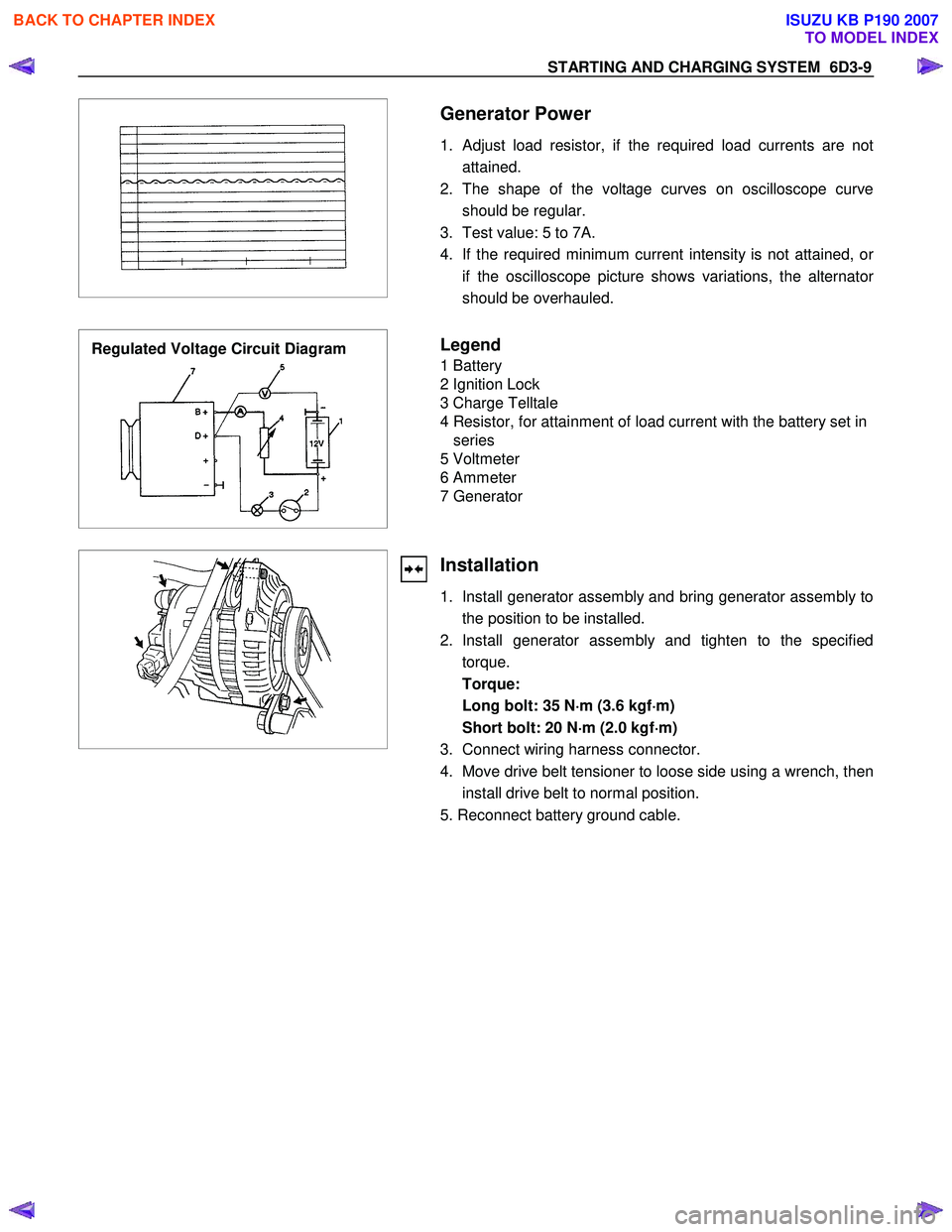
Generator Power
1. Adjust load resistor, if the required load currents are not attained.
2. The shape of the voltage curves on oscilloscope curve should be regular.
3. Test value: 5 to 7A.
4. If the required minimum current intensity is not attained, o
r
if the oscilloscope picture shows variations, the alternator
should be overhauled.
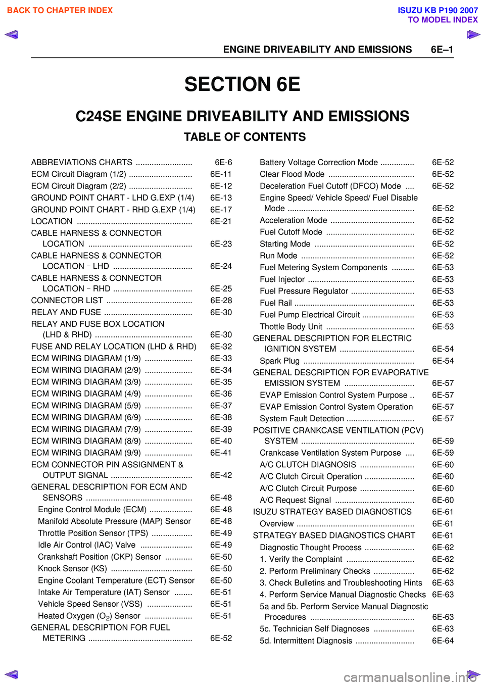
Regulated Voltage Circuit Diagram
Legend
1 Battery
2 Ignition Lock
3 Charge Telltale
4 Resistor, for attainment of load current with the battery set in series
5 Voltmeter
6 Ammeter
7 Generator
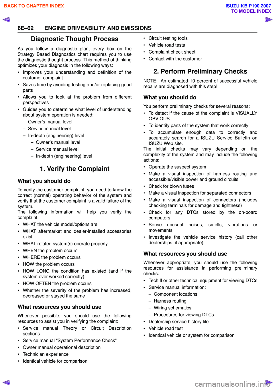
Installation
1. Install generator assembly and bring generator assembly to the position to be installed.
2. Install generator assembly and tighten to the specified torque.
Torque:
Long bolt: 35 N ⋅
⋅⋅
⋅
m (3.6 kgf ⋅
⋅⋅
⋅
m)
Short bolt: 20 N ⋅
⋅⋅
⋅
m (2.0 kgf ⋅
⋅⋅
⋅
m)
3. Connect wiring harness connector.
4. Move drive belt tensioner to loose side using a wrench, then install drive belt to normal position.
5. Reconnect battery ground cable.
BACK TO CHAPTER INDEX
TO MODEL INDEX
ISUZU KB P190 2007
Page 2160 of 6020

6D3-12 STARTING AND CHARGING SYSTEM
Diagnosis
The EP regulator incorporates diagnostics which will illuminate
the warning lamp as a result of fault conditions in the generator
and external circuitry.
These conditions include:
1.
An open circuit in the regulator battery sensing wire (S
Terninal)
2. An open circuit or excessive voltage drop in the B+ cable.
3. An open circuit in the generator phase connection.
4. Overcharging of the battery.
5. Regulator output stage short circuit.
6. Open circuit rotor.
The regulator compares the voltage at B+ with the voltage at
the "S" terminal connceted to battery positive. If the voltage
differential exceeds a predetermined threshold, the regulator
will operate in backup mode to limit the output voltage to a safe
level. The warning lamp; will remain illuminated as along as
these conditions prevail.
Sources of high resistance which will trigger the warning lamp
are:
a. Poor contact in wiring harness connectors.
b. Poor contact between rectifier and regulator.
c. High resistance in fusible link assembly.
Caution:
When bench testing the generator it is important that the
warning lamp wattage of 2 watts is not exceeded.
Reversal of the "S" and "L" on the regulator will damage
the regulator.
The correct plug for the regulator is a 9 122 067 011 for the
Bosch tye and for the Shinagawa connector the number is
X02FW.
See appendix 1 for daignostic matrix.
Before testing or disassembling the generator please observe
the following points.
1. W hen testing the diodes with AC type testers the RMS.
Vlotage output must not exceed 12.0 volts, it is
recommended that the stator should be disconnected
during this test.
2. W here zener power diodes are used, the breakdown voltage should be tested to ensure all diodes have the
same zener voltage.
3. Insulation tests on the rotor and stator should use a voltage not exceeding 110v for a series test lamp. The rectifie
r
must be disconnected from the stator prior to testing.
4. W hen carrying out repairs to the charging system always disconnected the battery negative first, and reconnect it
last.
BACK TO CHAPTER INDEX
TO MODEL INDEX
ISUZU KB P190 2007
Page 2171 of 6020

SECTION 6E
TABLE OF CONTENTS
C24SE ENGINE DRIVEABILITY AND EMISSIONS
ABBREVIATIONS CHARTS ......................... 6E-6
ECM Circuit Diagram (1/2) ............................ 6E-11
ECM Circuit Diagram (2/2) ............................ 6E-12
GROUND POINT CHART - LHD G.EXP (1/4) 6E-13
GROUND POINT CHART - RHD G.EXP (1/4) 6E-17
LOCATION ................................................... 6E-21
CABLE HARNESS & CONNECTOR LOCATION .............................................. 6E-23
CABLE HARNESS & CONNECTOR LOCATION - LHD ................................... 6E-24
CABLE HARNESS & CONNECTOR LOCATION - RHD ................................... 6E-25
CONNECTOR LIST ...................................... 6E-28
RELAY AND FUSE ....................................... 6E-30
RELAY AND FUSE BOX LOCATION (LHD & RHD) ........................................... 6E-30
FUSE AND RELAY LOCATION (LHD & RHD) 6E-32
ECM WIRING DIAGRAM (1/9) ..................... 6E-33
ECM WIRING DIAGRAM (2/9) ..................... 6E-34
ECM WIRING DIAGRAM (3/9) ..................... 6E-35
ECM WIRING DIAGRAM (4/9) ..................... 6E-36
ECM WIRING DIAGRAM (5/9) ..................... 6E-37
ECM WIRING DIAGRAM (6/9) ..................... 6E-38
ECM WIRING DIAGRAM (7/9) ..................... 6E-39
ECM WIRING DIAGRAM (8/9) ..................... 6E-40
ECM WIRING DIAGRAM (9/9) ..................... 6E-41
ECM CONNECTOR PIN ASSIGNMENT & OUTPUT SIGNAL .................................... 6E-42
GENERAL DESCRIPTION FOR ECM AND SENSORS ............................................... 6E-48
Engine Control Module (ECM) ................... 6E-48
Manifold Absolute Pressure (MAP) Sensor 6E-48
Throttle Position Sensor (TPS) .................. 6E-49
Idle Air Control (IAC) Valve ....................... 6E-49
Crankshaft Position (CKP) Sensor ............ 6E-50
Knock Sensor (KS) .................................... 6E-50
Engine Coolant Temperature (ECT) Sensor 6E-50
Intake Air Temperature (IAT) Sensor ........ 6E-51
Vehicle Speed Sensor (VSS) .................... 6E-51
Heated Oxygen (O
2) Sensor ..................... 6E-51
GENERAL DESCRIPTION FOR FUEL METERING .............................................. 6E-52 Battery Voltage Correction Mode ............... 6E-52
Clear Flood Mode ...................................... 6E-52
Deceleration Fuel Cutoff (DFCO) Mode .... 6E-52
Engine Speed/ Vehicle Speed/ Fuel Disable Mode ........................................................ 6E-52
Acceleration Mode ..................................... 6E-52
Fuel Cutoff Mode ....................................... 6E-52
Starting Mode ............................................ 6E-52
Run Mode .................................................. 6E-52
Fuel Metering System Components .......... 6E-53
Fuel Injector ............................................... 6E-53
Fuel Pressure Regulator ............................ 6E-53
Fuel Rail ..................................................... 6E-53
Fuel Pump Electrical Circuit ....................... 6E-53
Thottle Body Unit ....................................... 6E-53
GENERAL DESCRIPTION FOR ELECTRIC IGNITION SYSTEM ................................. 6E-54
Spark Plug ................................................. 6E-54
GENERAL DESCRIPTION FOR EVAPORATIVE EMISSION SYSTEM ............................... 6E-57
EVAP Emission Control System Purpose .. 6E-57
EVAP Emission Control System Operation 6E-57
System Fault Detection .............................. 6E-57
POSITIVE CRANKCASE VENTILATION (PCV) SYSTEM .................................................. 6E-59
Crankcase Ventilation System Purpose .... 6E-59
A/C CLUTCH DIAGNOSIS ........................ 6E-60
A/C Clutch Circuit Operation ...................... 6E-60
A/C Clutch Circuit Purpose ........................ 6E-60
A/C Request Signal ................................... 6E-60
ISUZU STRATEGY BASED DIAGNOSTICS 6E-61
Overview .................................................... 6E-61
STRATEGY BASED DIAGNOSTICS CHART 6E-61 Diagnostic Thought Process ...................... 6E-62
1. Verify the Complaint .............................. 6E-62
2. Perform Preliminary Checks .................. 6E-62
3. Check Bulletins and Troubleshooting Hints 6E-63
4. Perform Service Manual Diagnostic Checks 6E-63
5a and 5b. Perform Service Manual Diagnostic Procedures .............................................. 6E-63
5c. Technician Self Diagnoses .................. 6E-63
5d. Intermittent Diagnosis .......................... 6E-64
6 E –1
E N GINE DRIV EABILITY AND E M IS SIONS
BACK TO CHAPTER INDEX
TO MODEL INDEX
ISUZU KB P190 2007
Page 2232 of 6020

6E–62 ENGINE DRIVEABILITY AND EMISSIONS
Diagnostic Thought Process
As you follow a diagnostic plan, every box on the
Strategy Based Diagnostics chart requires you to use
the diagnostic thought process. This method of thinking
optimizes your diagnosis in the following ways:
• Improves your understanding and definition of the customer complaint
• Saves time by avoiding testing and/or replacing good parts
• Allows you to look at the problem from different perspectives
• Guides you to determine what level of understanding about system operation is needed:
– Owner’s manual level
– Service manual level
– In-depth (engineering) level – Owner’s manual level
– Service manual level
– In-depth (engineering) level
1. Verify the Complaint
What you should do
To verify the customer complaint, you need to know the
correct (normal) operating behavior of the system and
verify that the customer complaint is a valid failure of the
system.
The following information will help you verify the
complaint:
• WHAT the vehicle model/options are
• WHAT aftermarket and dealer-installed accessories exist
• WHAT related system(s) operate properly
• WHEN the problem occurs
• WHERE the problem occurs
• HOW the problem occurs
• HOW LONG the condition has existed (and if the system ever worked correctly)
• HOW OFTEN the problem occurs
• Whether the severity of the problem has increased, decreased or stayed the same
What resources you should use
Whenever possible, you should use the following
resources to assist you in verifying the complaint:
• Service manual Theory or Circuit Description sections
• Service manual “System Performance Check”
• Owner manual operational description
• Technician experience
• Identical vehicle for comparison • Circuit testing tools
• Vehicle road tests
• Complaint check sheet
• Contact with the customer
2. Perform Preliminary Checks
NOTE: An estimated 10 percent of successful vehicle
repairs are diagnosed with this step!
What you should do
You perform preliminary checks for several reasons:
• To detect if the cause of the complaint is VISUALLY OBVIOUS
• To identify parts of the system that work correctly
• To accumulate enough data to correctly and accurately search for a ISUZU Service Bulletin on
ISUZU Web site.
The initial checks may vary depending on the
complexity of the system and may include the following
actions:
• Operate the suspect system
• Make a visual inspection of harness routing and accessible/visible power and ground circuits
• Check for blown fuses
• Make a visual inspection for separated connectors
• Make a visual inspection of connectors (includes checking terminals for damage and tightness)
• Check for any DTCs stored by the on-board computers
• Sense unusual noises, smells, vibrations or movements
• Investigate the vehicle service history (call other dealerships, if appropriate)
What resources you should use
Whenever appropriate, you should use the following
resources for assistance in performing preliminary
checks:
• Tech II or other technical equipment for viewing DTCs
• Service manual information: – Component locations
– Harness routing
– Wiring schematics
– Procedures for viewing DTCs
• Dealership service history file
• Vehicle road test
• Identical vehicle or system for comparison
BACK TO CHAPTER INDEX
TO MODEL INDEX
ISUZU KB P190 2007
Page 2234 of 6020

6E–64 ENGINE DRIVEABILITY AND EMISSIONS
– Are there areas subjected to vibration ormovement (engine, transmission or
suspension)?
– Are there areas exposed to moisture, road salt or other corrosives (battery acid, oil or other
fluids)?
– Are there common mounting areas with other systems/components?
– Have previous repairs been performed to wiring, connectors, components or mounting areas
(causing pinched wires between panels and
drivetrain or suspension components without
causing and immediate problem)?
– Does the vehicle have aftermarket or dealer- installed equipment (radios, telephone, etc.)
Step 2: Isolate the problem
At this point, you should have a good idea of what could
cause the present condition, as well as could not cause
the condition. Actions to take include the following:
• Divide (and separate, where possible) the system or circuit into smaller sections
• Confine the problem to a smaller area of the vehicle (start with main harness connections while removing
panels and trim as necessary in order to eliminate
large vehicle sections from further investigation)
• For two or more circuits that do not share a common power or ground, concentrate on areas where
harnesses are routed together or connectors are
shared (refer to the following hints)
Hints
Though the symptoms may vary, basic electrical failures
are generally caused by:
• Loose connections: – Open/high resistance in terminals, splices,connectors or grounds
• Incorrect connector/harness routing (usually in new vehicles or after a repair has been made):
– Open/high resistance in terminals, splices, connectors of grounds
• Corrosion and wire damage:
– Open/high resistance in terminals, splices,connectors of grounds
• Component failure: – Opens/short and high resistance in relays,modules, switches or loads
• Aftermarket equipment affecting normal operation of other systems
You may isolate circuits by:
• Unplugging connectors or removing a fuse to separate one part of the circuit from another part
• Operating shared circuits and eliminating those that function normally from the suspect circuit
• If only one component fails to operate, begin testing at the component
• If a number of components do no operate, begin tests at the area of commonality (such as power sources,
ground circuits, switches or major connectors)
What resources you should use
Whenever appropriate, you should use the following
resources to assist in the diagnostic process:
• Service manual
• Technical equipment (for data analysis)
• Experience
• Technical Assistance
• Circuit testing tools
5d. Intermittent Diagnosis
By definition, an intermittent problem is one that does
not occur continuously and will occur when certain
conditions are met. All these conditions, however, may
not be obvious or currently known. Generally,
intermittents are caused by:
• Faulty electrical connections and wiring
• Malfunctioning components (such as sticking relays, solenoids, etc.)
• EMI/RFI (Electromagnetic/radio frequency interference)
• Aftermarket equipment
Intermittent diagnosis requires careful analysis of
suspected systems to help prevent replacing good
parts. This may involve using creativity and ingenuity to
interpret customer complaints and simulating all
external and internal system conditions to duplicate the
problem.
What you should do
Step 1: Acquire information
A thorough and comprehensive customer check sheet
is critical to intermittent problem diagnosis. You should
require this, since it will dictate the diagnostic starting
point. The vehicle service history file is another
source for accumulating information about the
complaint.
Step 2: Analyze the intermittent problem
Analyze the customer check sheet and service history
file to determine conditions relevant to the suspect
system(s).
Using service manual information, you must identify,
trace and locate all electrical circuits related to the
malfunctioning system(s). If there is more than one
system failure, you should identify, trace and locate
areas of commonality shared by the suspect circuits.
BACK TO CHAPTER INDEX
TO MODEL INDEX
ISUZU KB P190 2007