fuse chart ISUZU KB P190 2007 Workshop Owner's Guide
[x] Cancel search | Manufacturer: ISUZU, Model Year: 2007, Model line: KB P190, Model: ISUZU KB P190 2007Pages: 6020, PDF Size: 70.23 MB
Page 3484 of 6020

Engine Management – V6 – Diagnostics Page 6C1-2–206
• The engine is running.
Conditions for Setting the DTC
DTC P2227
The ECM detects the BARO pressure changed greater than 5 kPa within 20 seconds or the BARO pressure changed
greater than 30 kPa since the last ignition cycle.
DTC P2228
The ECM detects the BARO sensor signal voltage is less than 0.20 V.
DTC P2229
The ECM detects the BARO sensor signal voltage is greater than 4.8 V for longer than 2.0 seconds.
Conditions for Clearing DTC
The BARO pressure sensor circuit DTCs are Type ‘B’ DTC. Refer to 1.4 Diagnostic Trouble Codes in this Section, for
action taken when a Type ‘B’ DTC sets and conditions for clearing Type ‘B’ DTCs.
Additional Information
• Refer to 6C1-1 Engine Management – V6 – General Information for details of the BARO Sensor operation.
• For an intermittent fault condition, refer to 5.2 Intermittent Fault Conditions in this Section.
• Since fault condition in a wiring connector may trigger DTCs, always test the connectors related to this diagnostic
procedure for shorted terminals or poor wiring connection before replacing any component. Refer to 8A Electrical -
Body and Chassis for information on electrical fault diagnosis.
• To assist diagnosis, refer to 3 W iring Diagrams and Connector Charts in this Section, for the system wiring
diagram and connector charts.
Test Description
The following numbers refer to the step numbers in the diagnostic table:
4 Test signal circuit of the BARO sensor. This circuit should display a voltage within the specified range.
5 Measures the integrity of the TP sensor low reference circuit. Removal of the ECM Fuse 29 enables the ECM to power down completely prior to the test procedure.
DTC P2227 P2228 or P2229 Diagnostic Table
Step Action Yes No
1 Has the Diagnostic System Check been performed?
Go to Step 2 Refer to
4.4 Diagnostic
System Check in this Section
2 1 Switch off the ignition for 30 seconds.
2 Operate the vehicle within the conditions for running the DTC.
3 Using Tech 2, select the DTC display function.
Does DTC P2227, P2228 or P2229 fail this ignition cycle? Go to Step 3 Refer to Additional
Information in this DTC
BACK TO CHAPTER INDEX
TO MODEL INDEX
ISUZU KB P190 2007
Page 3485 of 6020

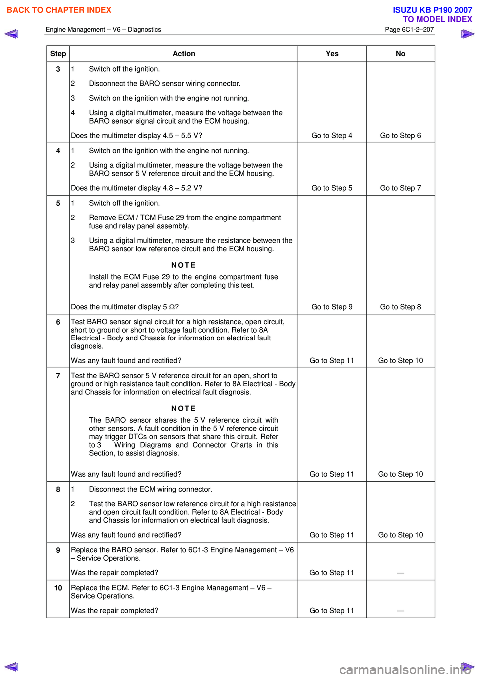
Engine Management – V6 – Diagnostics Page 6C1-2–207
Step Action Yes
No
3 1 Switch off the ignition.
2 Disconnect the BARO sensor wiring connector.
3 Switch on the ignition with the engine not running.
4 Using a digital multimeter, measure the voltage between the BARO sensor signal circuit and the ECM housing.
Does the multimeter display 4.5 – 5.5 V? Go to Step 4 Go to Step 6
4 1 Switch on the ignition with the engine not running.
2 Using a digital multimeter, measure the voltage between the BARO sensor 5 V reference circuit and the ECM housing.
Does the multimeter display 4.8 – 5.2 V? Go to Step 5 Go to Step 7
5 1 Switch off the ignition.
2 Remove ECM / TCM Fuse 29 from the engine compartment fuse and relay panel assembly.
3 Using a digital multimeter, measure the resistance between the BARO sensor low reference circuit and the ECM housing.
NOTE
Install the ECM Fuse 29 to the engine compartment fuse
and relay panel assembly after completing this test.
Does the multimeter display 5 Ω? Go to Step 9 Go to Step 8
6 Test BARO sensor signal circuit for a high resistance, open circuit,
short to ground or short to voltage fault condition. Refer to 8A
Electrical - Body and Chassis for information on electrical fault
diagnosis.
W as any fault found and rectified? Go to Step 11 Go to Step 10
7 Test the BARO sensor 5 V reference circuit for an open, short to
ground or high resistance fault condition. Refer to 8A Electrical - Body
and Chassis for information on electrical fault diagnosis.
NOTE
The BARO sensor shares the 5 V reference circuit with
other sensors. A fault condition in the 5 V reference circuit
may trigger DTCs on sensors that share this circuit. Refer
to 3 W iring Diagrams and Connector Charts in this
Section, to assist diagnosis.
W as any fault found and rectified? Go to Step 11 Go to Step 10
8 1 Disconnect the ECM wiring connector.
2 Test the BARO sensor low reference circuit for a high resistance and open circuit fault condition. Refer to 8A Electrical - Body
and Chassis for information on electrical fault diagnosis.
W as any fault found and rectified? Go to Step 11 Go to Step 10
9 Replace the BARO sensor. Refer to 6C1-3 Engine Management – V6
– Service Operations.
W as the repair completed? Go to Step 11 —
10 Replace the ECM. Refer to 6C1-3 Engine Management – V6 –
Service Operations.
W as the repair completed? Go to Step 11 —
BACK TO CHAPTER INDEX
TO MODEL INDEX
ISUZU KB P190 2007
Page 4312 of 6020

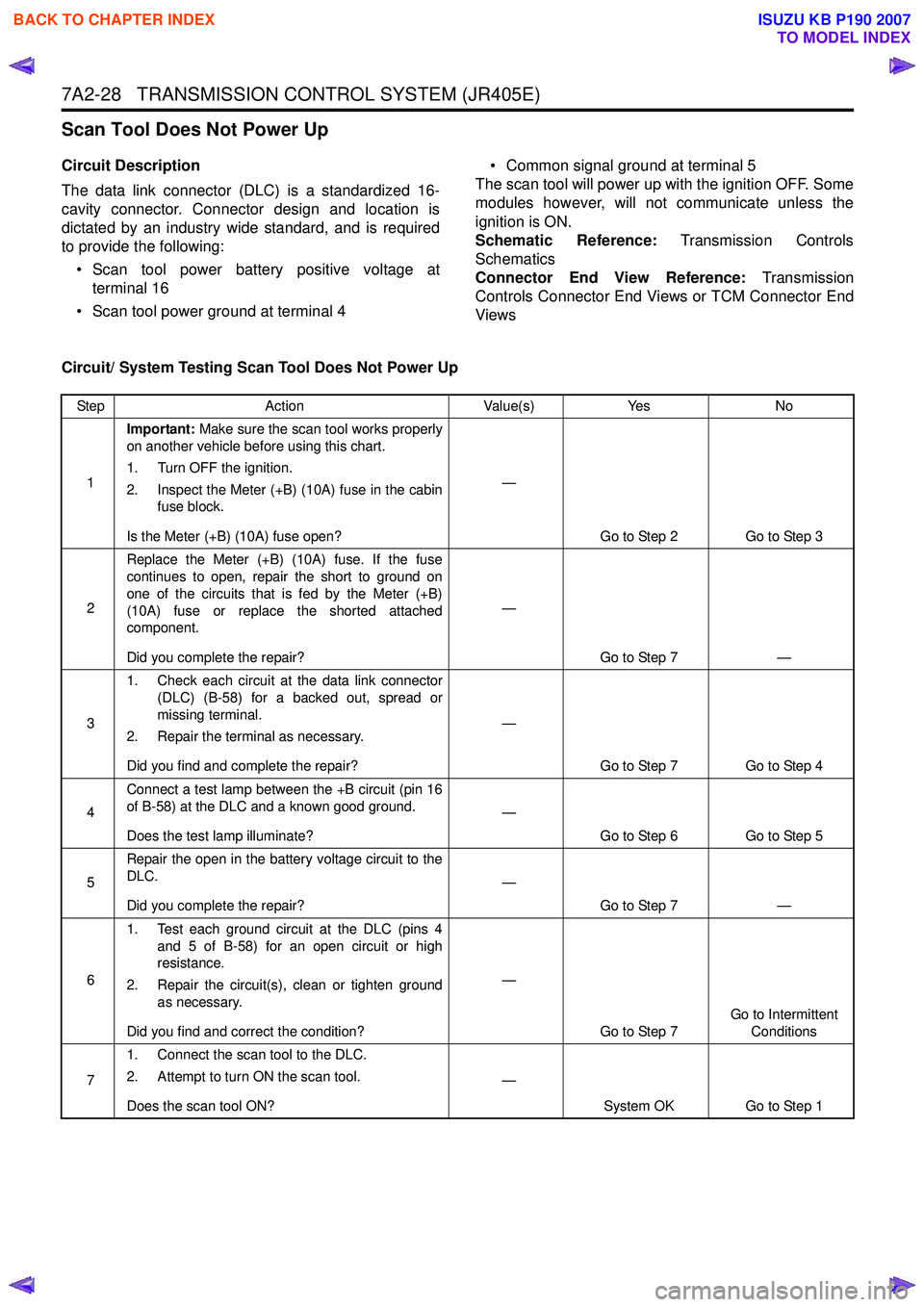
7A2-28 TRANSMISSION CONTROL SYSTEM (JR405E)
Scan Tool Does Not Power Up
Circuit Description
The data link connector (DLC) is a standardized 16-
cavity connector. Connector design and location is
dictated by an industry wide standard, and is required
to provide the following:
• Scan tool power battery positive voltage at terminal 16
• Scan tool power ground at terminal 4 • Common signal ground at terminal 5
The scan tool will power up with the ignition OFF. Some
modules however, will not communicate unless the
ignition is ON.
Schematic Reference: Transmission Controls
Schematics
Connector End View Reference: Transmission
Controls Connector End Views or TCM Connector End
Views
Circuit/ System Testing Scan Tool Does Not Power Up
Step Action Value(s)Yes No
1 Important:
Make sure the scan tool works properly
on another vehicle before using this chart.
1. Turn OFF the ignition.
2. Inspect the Meter (+B) (10A) fuse in the cabin fuse block.
Is the Meter (+B) (10A) fuse open? —
Go to Step 2 Go to Step 3
2 Replace the Meter (+B) (10A) fuse. If the fuse
continues to open, repair the short to ground on
one of the circuits that is fed by the Meter (+B)
(10A) fuse or replace the shorted attached
component.
Did you complete the repair? —
Go to Step 7 —
3 1. Check each circuit at the data link connector
(DLC) (B-58) for a backed out, spread or
missing terminal.
2. Repair the terminal as necessary.
Did you find and complete the repair? —
Go to Step 7 Go to Step 4
4 Connect a test lamp between the +B circuit (pin 16
of B-58) at the DLC and a known good ground.
Does the test lamp illuminate? —
Go to Step 6 Go to Step 5
5 Repair the open in the battery voltage circuit to the
DLC.
Did you complete the repair? —
Go to Step 7 —
6 1. Test each ground circuit at the DLC (pins 4
and 5 of B-58) for an open circuit or high
resistance.
2. Repair the circuit(s), clean or tighten ground as necessary.
Did you find and correct the condition? —
Go to Step 7 Go to Intermittent
Conditions
7 1. Connect the scan tool to the DLC.
2. Attempt to turn ON the scan tool.
Does the scan tool ON? —
System OK Go to Step 1
BACK TO CHAPTER INDEX
TO MODEL INDEX
ISUZU KB P190 2007
Page 4929 of 6020

TRANSFER CONTROL SYSTEM 7D1-55
Cannot shift from 2WD to 4H or 4L.
When shifting from 2H to other position, the indicator (4WD, 4Lo, Check4WD, neutral)
does not respond.
Step Action Yes No
1 Is the ignition switch ON? Go to step 2.
Turn the ignition switch ON and
trace this chart from the
beginning.
2 Does the transfer-related
indicators (4W D, 4Lo, Check
4W D, neutral) light up for 2
seconds when the ignition switch
is turned ON? Failed operation switch. Or,
Failed controller. Indicator lamp burnt out.
Disconnected harness wire.
After repairing, trace this chart
from the beginning.
Even after correction step 1-1(*), 4WD indicator blinks at 4Hz and changes to 2H after 10
seconds.
Step Action Yes No
1 Is the ignition switch ON? Go to step 2.
Turn the ignition switch ON and
trace this chart from the
beginning.
2 Does the transfer-related
indicators (4W D, 4Lo, Check
4W D, neutral) light up for 2
seconds when the ignition switch
is turned ON? Go to step 3.
Indicator lamp burnt out.
Disconnected harness wire.
After repairing, trace this chart
from the beginning.
3 After 2 seconds, check that the
Check4W D lamp is ON or OFF.
Is the Check4W D lamp OFF? Go to step 4.
Failed actuator position detection
switch (LS1, LS2, LS3, LS4,
GND).
Short or disconnection of harness
of this detection switch.
After repairing, trace this chart
from the beginning.
4 Press the 4H button.
Is sound of relay heard from the
transfer control? Go to step 5.
Failed controller.
Replace the controller and trace
this chart from the beginning.
5 Is the sound of a running motor
heard? Failed control system of the
transfer mechanism. Check and
repair and trace this chart from
the beginning. Failed actuator motor.
Disconnected controller motor
drive output circuit, GND short
circuit. +B fuse blown out.
Disconnection of that harness.
After repairing, trace this chart
from the beginning.
*Before determining a trouble (Non-trouble mode)
BACK TO CHAPTER INDEX
TO MODEL INDEX
ISUZU KB P190 2007
Page 4931 of 6020

TRANSFER CONTROL SYSTEM 7D1-57
After operation, indicator of target position blinks for 1.5 sec. at 2Hz, return to 2H
condition (4WD indicator going out)
Step Action Yes No
1 Keep pressing the 4H button
(about 10 seconds).
Does the 4W D indicator blink at
2Hz for 15 seconds and then
blink at 4Hz? Failed actuator motor.
Disconnection of controller motor
drive output circuit, or GND short.
+B fuse blown out.
Disconnection of that harness.
After repairing, trace this chart
from the beginning. Go to step 2.
2
Press the 4H button.
Is the sound of relay heard from
the transfer controller? Go to step 3.
Failed controller.
Replace the controller and trace
this chart from the beginning.
3 Is the sound of running motor
heard? Failed control system of the
transfer mechanism. Check and
repair and trace this chart from
the beginning. Failed actuator motor.
Disconnection or GND short of
controller motor drive output
circuit.
After repairing, trace this chart
from the beginning.
BACK TO CHAPTER INDEX
TO MODEL INDEX
ISUZU KB P190 2007
Page 5345 of 6020

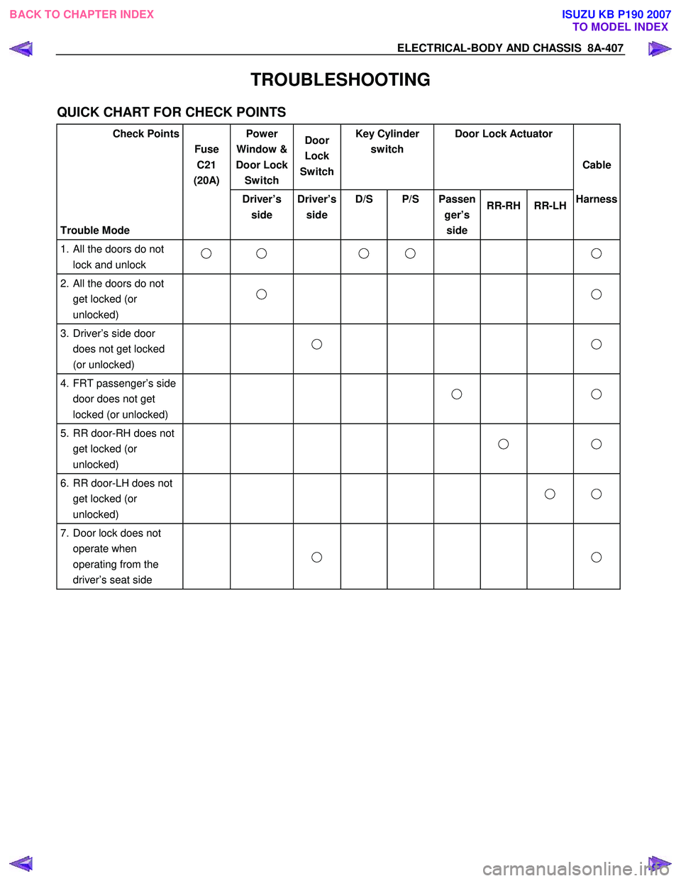
ELECTRICAL-BODY AND CHASSIS 8A-407
TROUBLESHOOTING
QUICK CHART FOR CHECK POINTS
Check Points Fuse C21
(20A) Power
Window &
Door Lock Switch Door
Lock
Switch Key Cylinder
switch Door Lock Actuator
Cable
Trouble Mode Driver’s
side Driver’s
side D/S P/S Passen
ger’s side RR-RH RR-LH
Harness
1. All the doors do not
lock and unlock
2. All the doors do not get locked (or
unlocked)
3. Driver’s side door
does not get locked
(or unlocked)
4. FRT passenger’s side
door does not get
locked (or unlocked)
5. RR door-RH does not
get locked (or
unlocked)
6. RR door-LH does not
get locked (or
unlocked)
7. Door lock does not
operate when
operating from the
driver’s seat side
BACK TO CHAPTER INDEX
TO MODEL INDEXISUZU KB P190 2007
Page 5410 of 6020

8A-472 ELECTRICAL-BODY AND CHASSIS
TROUBLESHOOTING
QUICK CHART FOR CHECK POINT
Check Point Fuse Door Mirror Door Mirror
Trouble Mode C11
(10A) Control
Switch LH RH
1. Mirrors on the both sides do not operate
2. Mirror on the left (or right) side does not
operate
3. Mirrors on the both sides operate only in
the vertical
(or horizontal) direction
4. Mirror on the left side operates only in
the vertical
(or horizontal) direction
5. Mirror on the right side operates only in
the vertical
(or horizontal) direction
Cable
Harness
BACK TO CHAPTER INDEX
TO MODEL INDEXISUZU KB P190 2007
Page 5477 of 6020

ELECTRICAL-BODY AND CHASSIS 8A-539
Keyless Entry System Check
Step Action Value (s) Yes No
1 Check the fuse for the keyless entry power feed
circuit. (EB16 10A)
If a problem found, repair as necessary.
W as the problem found? — Verify repair Go to Step 2
2
1. Check the KCU (Keyless Entry Control Unit)
ground circuit for an open, or short to voltage.
Also, check the KCU ignition feed circuit for an
open or short to ground and the KCU ground
circuit for an open.
2. If a problem is found, repair as necessary.
W as the problem found? — Verify repair Go to Step 3
3
1. Check the front drive side SW circuit for an open,
or short to voltage.
2. If a problem is found, repair as necessary.
W as the problem found? — Verify repair Go to Step 4
4
1. Check the operation "Lock / unlock" by using
transmitter (Remote key) on the vehicle.
W as the problem found? — Go to
Diagnostic Chart Go to
Diagnostic Aids
BACK TO CHAPTER INDEX TO MODEL INDEXISUZU KB P190 2007
Page 5656 of 6020

SUPPLEMENTAL RESTRAINT SYSTEM 9A-21
On–Vehicle Service
Service Precaution
WARNING: WHEN PERFORMING SERVICE ON OR
AROUND SRS COMPONENTS OR SRS WIRING,
FOLLOW THE PROCEDURES LISTED BELOW TO
TEMPORARILY DISABLE THE SRS. FAILURE TO
FOLLOW PROCEDURES COULD RESULT IN
POSSIBLE AIR BAG DEPLOYMENT, PERSONAL
INJURY OR OTHERWISE UNNECESSARY SRS
REPAIRS.
The SRS control unit in Driver–Passenger SRS can
maintain sufficient voltage to cause a deployment fo
r
up to 15 seconds after the ignition switch is turned
“OFF,” the battery is disconnected, or the fuse
powering the SRS control unit is removed.
Many of the service procedures require removal of the
“SRS” fuse, and disconnection of the air bag assembl
y
from the deployment loop to avoid an accidental
deployment. If the air bag assembly is disconnected
from the deployment loop as noted in the “Disabling
the SRS” procedure that follows, service can begin
immediately without waiting for the 15 second time
period to expire.
Disabling The SRS
Removal
Turn the ignition switch to “LOCK” and remove the
key.
1. Remove the SRS fuse “SRS”, from the side of the driver’s side of the instrument panel fuse block o
r
disconnect the battery.
2. Disconnect the yellow connector at the base of the steering column.
3. Remove the glove box assembly, refer to “Passenger Air Bag Assembly Replacement” in
this manual.
4. Disconnect the yellow connector behind the glove box assembly.
CAUTION: With the “SRS” fuse removed and
ignition switched “ON”, the “SRS” warning lamp
will be “ON”. This is normal operation and does
not indicate an SRS malfunction.
Enabling The SRS
Installation
CAUTION: Never use the air bag assembly from
another vehicle or different model year air bag
assembly.
Use only a new air bag assembly matched to the
TFR/S which is being repaired.
Turn the ignition switch to “LOCK” and remove the
key.
1. Connect the yellow connector passenger air bag assembly.
2. Install the glove box assembly. Refer to “Passenger air bag assembly replacement” in this
manual.
3. Connect the yellow connector at the base of the steering column.
4. Install the “AIR BAG” fuse “SRS” to the side of the driver’s side of the instrument panel fuse block o
r
connect the battery.
Turn the ignition switch to “ON” and verify that the
“SRS” warning lamp flashes seven times and then
turns to “LOCK”. If it does not operate as described,
perform the “SRS Diagnostic System Check” in this
manual.
Handling / Installation / Diagnosis
1. The air bag assembly should not be subjected to temperatures above 65
°C (150°F).
2. The air bag assembly, and SRS control unit, should not be used if they have been dropped from
a height of 100 centimeters (3.28 feet) or more.
3. W hen the SRS control unit is replaced, it must be oriented with the arrow on the sensor pointing
toward the front of the vehicle. It is very important
for the SRS control unit to be located flat on the
mounting surface, parallel to the vehicle datum
line. It is important that the SRS control unit
mounting surface is free of any dirt or other foreign
material.
4. Do not apply power to the SRS unless all components are connected or a diagnostic chart
requests it, as this will set a diagnostic trouble
code.
5. The “SRS Diagnostic System Check” must be the starting point of any SRS diagnostics. The “SRS
Diagnostic System Check” will verify proper “SRS”
warning lamp operation and will lead you to the
correct chart to diagnose any SRS malfunctions.
Bypassing these procedures may result in
extended diagnostic time, incorrect diagnosis, and
incorrect parts replacement.
BACK TO CHAPTER INDEX TO MODEL INDEXISUZU KB P190 2007
Page 5667 of 6020

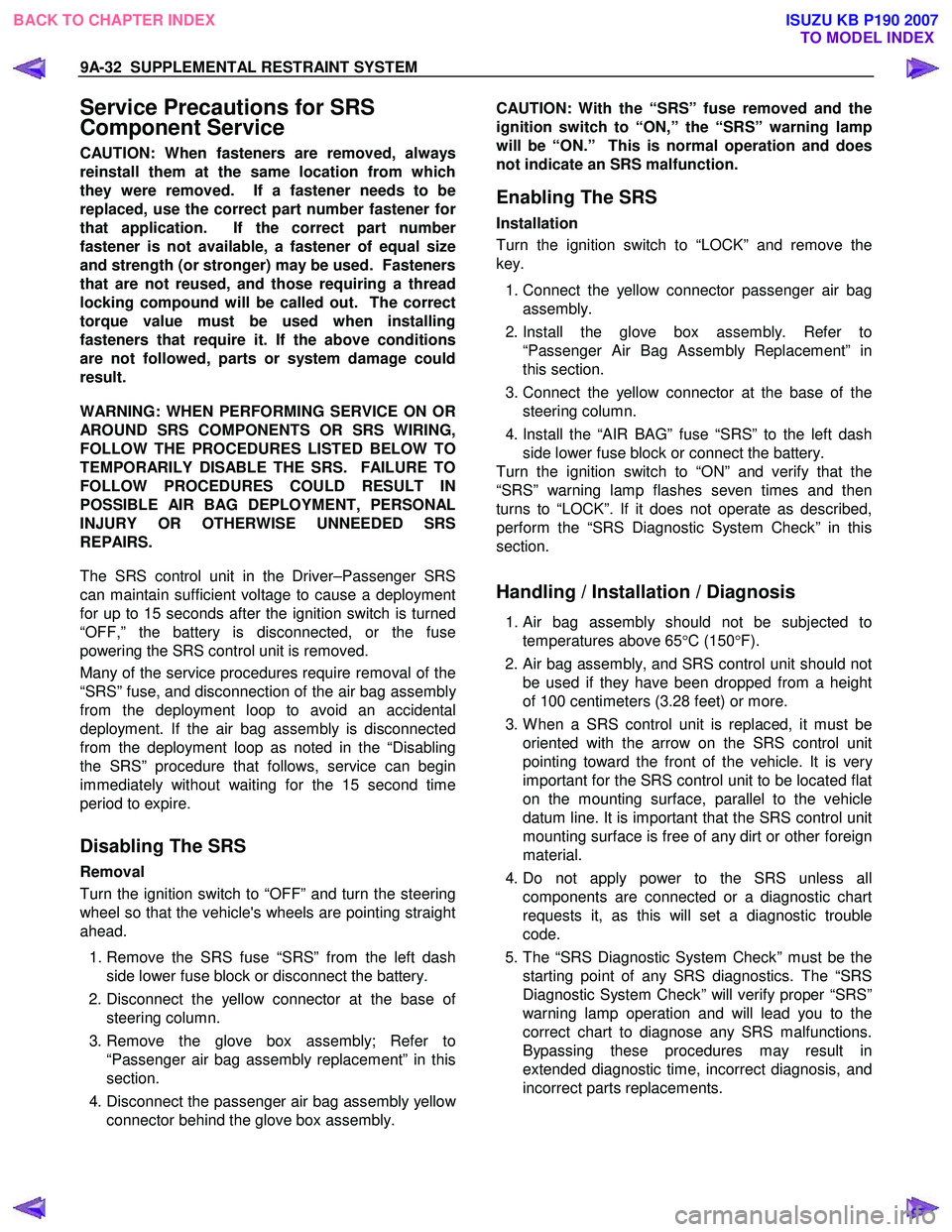
9A-32 SUPPLEMENTAL RESTRAINT SYSTEM
Service Precautions for SRS
Component Service
CAUTION: When fasteners are removed, always
reinstall them at the same location from which
they were removed. If a fastener needs to be
replaced, use the correct part number fastener fo
r
that application. If the correct part number
fastener is not available, a fastener of equal size
and strength (or stronger) may be used. Fasteners
that are not reused, and those requiring a thread
locking compound will be called out. The correct
torque value must be used when installing
fasteners that require it. If the above conditions
are not followed, parts or system damage could
result.
WARNING: WHEN PERFORMING SERVICE ON OR
AROUND SRS COMPONENTS OR SRS WIRING,
FOLLOW THE PROCEDURES LISTED BELOW TO
TEMPORARILY DISABLE THE SRS. FAILURE TO
FOLLOW PROCEDURES COULD RESULT IN
POSSIBLE AIR BAG DEPLOYMENT, PERSONAL
INJURY OR OTHERWISE UNNEEDED SRS
REPAIRS.
The SRS control unit in the Driver–Passenger SRS
can maintain sufficient voltage to cause a deployment
for up to 15 seconds after the ignition switch is turned
“OFF,” the battery is disconnected, or the fuse
powering the SRS control unit is removed.
Many of the service procedures require removal of the
“SRS” fuse, and disconnection of the air bag assembl
y
from the deployment loop to avoid an accidental
deployment. If the air bag assembly is disconnected
from the deployment loop as noted in the “Disabling
the SRS” procedure that follows, service can begin
immediately without waiting for the 15 second time
period to expire.
Disabling The SRS
Removal
Turn the ignition switch to “OFF” and turn the steering
wheel so that the vehicle's wheels are pointing straight
ahead.
1. Remove the SRS fuse “SRS” from the left dash side lower fuse block or disconnect the battery.
2. Disconnect the yellow connector at the base o
f
steering column.
3. Remove the glove box assembly; Refer to “Passenger air bag assembly replacement” in this
section.
4. Disconnect the passenger air bag assembly yello
w
connector behind the glove box assembly.
CAUTION: With the “SRS” fuse removed and the
ignition switch to “ON,” the “SRS” warning lamp
will be “ON.” This is normal operation and does
not indicate an SRS malfunction.
Enabling The SRS
Installation
Turn the ignition switch to “LOCK” and remove the
key.
1. Connect the yellow connector passenger air bag assembly.
2. Install the glove box assembly. Refer to “Passenger Air Bag Assembly Replacement” in
this section.
3. Connect the yellow connector at the base of the steering column.
4. Install the “AIR BAG” fuse “SRS” to the left dash side lower fuse block or connect the battery.
Turn the ignition switch to “ON” and verify that the
“SRS” warning lamp flashes seven times and then
turns to “LOCK”. If it does not operate as described,
perform the “SRS Diagnostic System Check” in this
section.
Handling / Installation / Diagnosis
1. Air bag assembly should not be subjected to
temperatures above 65 °C (150 °F).
2.
Air bag assembly, and SRS control unit should not
be used if they have been dropped from a height
of 100 centimeters (3.28 feet) or more.
3. W hen a SRS control unit is replaced, it must be oriented with the arrow on the SRS control unit
pointing toward the front of the vehicle. It is ver
y
important for the SRS control unit to be located flat
on the mounting surface, parallel to the vehicle
datum line. It is important that the SRS control unit
mounting surface is free of any dirt or other foreign
material.
4. Do not apply power to the SRS unless all components are connected or a diagnostic chart
requests it, as this will set a diagnostic trouble
code.
5. The “SRS Diagnostic System Check” must be the starting point of any SRS diagnostics. The “SRS
Diagnostic System Check” will verify proper “SRS”
warning lamp operation and will lead you to the
correct chart to diagnose any SRS malfunctions.
Bypassing these procedures may result in
extended diagnostic time, incorrect diagnosis, and
incorrect parts replacements.
BACK TO CHAPTER INDEX TO MODEL INDEXISUZU KB P190 2007