ISUZU KB P190 2007 Workshop Repair Manual
KB P190 2007
ISUZU
ISUZU
https://www.carmanualsonline.info/img/61/57177/w960_57177-0.png
ISUZU KB P190 2007 Workshop Repair Manual
Page 5053 of 6020
ELECTRICAL-BODY AND CHASSIS 8A-115
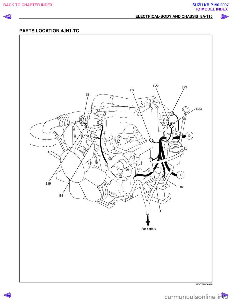
PARTS LOCATION 4JH1-TC
RTW 78AXF049401
BACK TO CHAPTER INDEX TO MODEL INDEXISUZU KB P190 2007
Page 5076 of 6020
8A-138 ELECTRICAL-BODY AND CHASSIS
CIRCUIT DIAGRAM 4JH1-TC (LHD) Sheet 1/2
RTW 78AXF004601
BACK TO CHAPTER INDEX TO MODEL INDEXISUZU KB P190 2007
Page 5077 of 6020
ELECTRICAL-BODY AND CHASSIS 8A-139
CIRCUIT DIAGRAM 4JH1-TC (LHD) Sheet 2/2
RTW 78AXF004701
BACK TO CHAPTER INDEX TO MODEL INDEXISUZU KB P190 2007
Page 5079 of 6020
ELECTRICAL-BODY AND CHASSIS 8A-141
REMOVAL AND INSTALLATION
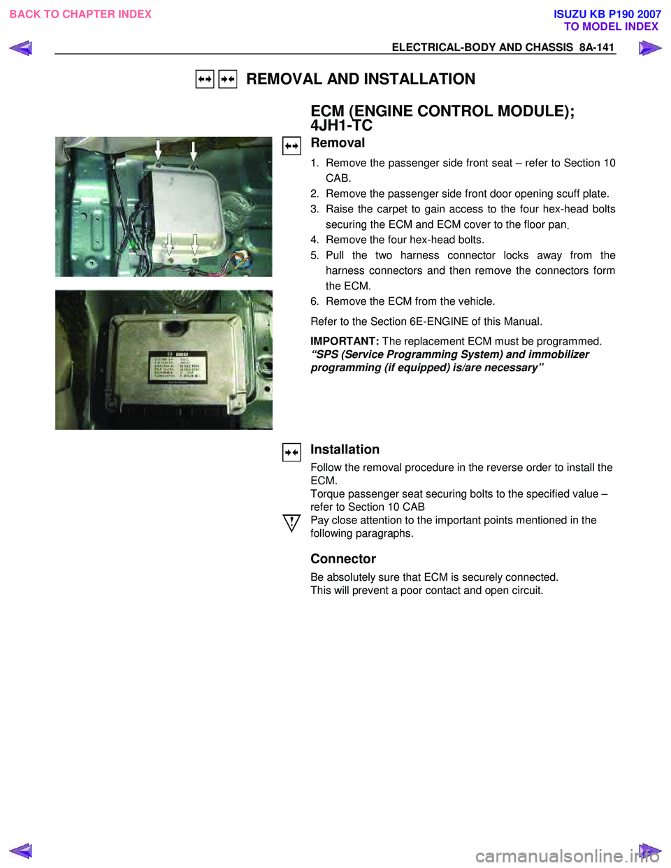
ECM (ENGINE CONTROL MODULE);
4JH1-TC
Removal
1. Remove the passenger side front seat – refer to Section 10
CAB.
2. Remove the passenger side front door opening scuff plate.
3. Raise the carpet to gain access to the four hex-head bolts securing the ECM and ECM cover to the floor pan .
4. Remove the four hex-head bolts.
5. Pull the two harness connector locks away from the harness connectors and then remove the connectors form
the ECM.
6. Remove the ECM from the vehicle.
Refer to the Section 6E-ENGINE of this Manual.
IMPORTANT: The replacement ECM must be programmed.
“SPS (Service Programming System) and immobilizer
programming (if equipped) is/are necessary”
Installation
Follow the removal procedure in the reverse order to install the
ECM.
Torque passenger seat securing bolts to the specified value –
refer to Section 10 CAB
Pay close attention to the important points mentioned in the
following paragraphs.
Connector
Be absolutely sure that ECM is securely connected.
This will prevent a poor contact and open circuit.
BACK TO CHAPTER INDEX TO MODEL INDEXISUZU KB P190 2007
Page 5095 of 6020
ELECTRICAL-BODY AND CHASSIS 8A-157
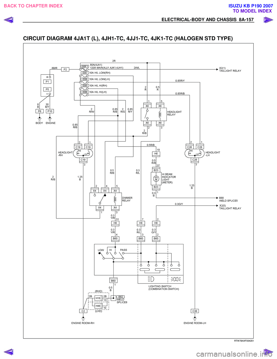
CIRCUIT DIAGRAM 4JA1T (L), 4JH1-TC, 4JJ1-TC, 4JK1-TC (HALOGEN STD TYPE)
RTW 78AXF004201
BACK TO CHAPTER INDEX TO MODEL INDEXISUZU KB P190 2007
Page 5096 of 6020
8A-158 ELECTRICAL-BODY AND CHASSIS
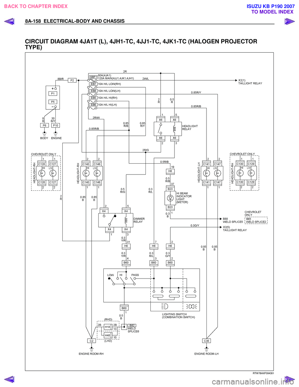
CIRCUIT DIAGRAM 4JA1T (L), 4JH1-TC, 4JJ1-TC, 4JK1-TC (HALOGEN PROJECTOR
TYPE)
RTW 78AXF004301
BACK TO CHAPTER INDEX TO MODEL INDEXISUZU KB P190 2007
Page 5097 of 6020
ELECTRICAL-BODY AND CHASSIS 8A-159
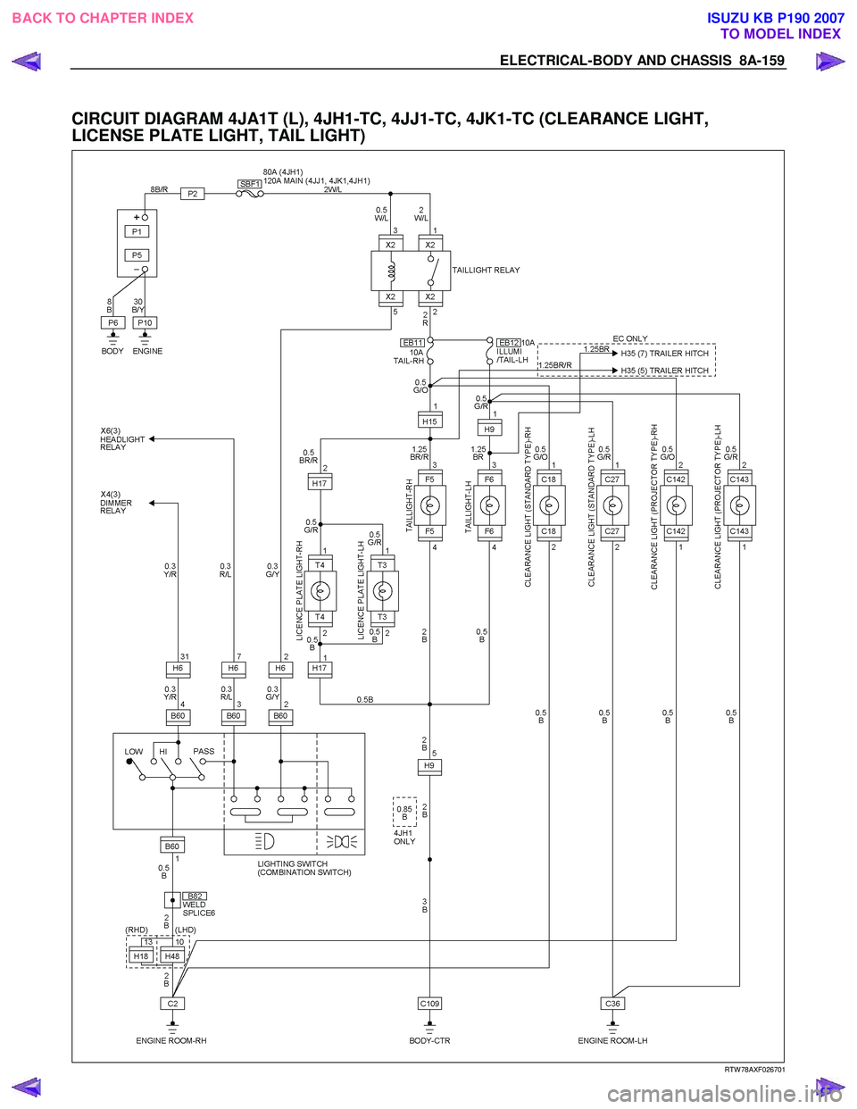
CIRCUIT DIAGRAM 4JA1T (L), 4JH1-TC, 4JJ1-TC, 4JK1-TC (CLEARANCE LIGHT,
LICENSE PLATE LIGHT, TAIL LIGHT)
RTW 78AXF026701
BACK TO CHAPTER INDEX TO MODEL INDEXISUZU KB P190 2007
Page 5147 of 6020
ELECTRICAL-BODY AND CHASSIS 8A-209
CIRCUIT DIAGRAM 4JH1-TC (LHD)
RTW A78XF013601
BACK TO CHAPTER INDEX
TO MODEL INDEXISUZU KB P190 2007
Page 5195 of 6020
ELECTRICAL-BODY AND CHASSIS 8A-257
CIRCUIT DIAGRAM 4JH1-TC
RTW 78AXF015001
BACK TO CHAPTER INDEX TO MODEL INDEXISUZU KB P190 2007
Page 5209 of 6020
ELECTRICAL-BODY AND CHASSIS 8A-271
CIRCUIT DIAGRAM 4JJ1-TC/4JK1-TC, 4JH1-TC
RTW 78AXF027201
BACK TO CHAPTER INDEX
TO MODEL INDEXISUZU KB P190 2007
