ISUZU KB P190 2007 Workshop Repair Manual
KB P190 2007
ISUZU
ISUZU
https://www.carmanualsonline.info/img/61/57177/w960_57177-0.png
ISUZU KB P190 2007 Workshop Repair Manual
Trending: spare wheel, engine coolant, coolant reservoir, change language, air bleeding, maintenance reset, rims
Page 5291 of 6020
ELECTRICAL-BODY AND CHASSIS 8A-353
REMOVAL AND INSTALLATION
RTW 780SH001701
This illustration is based on RHD model
METER ASSEMBLY
Removal
1. Meter Cluster Assembly
• Refer to the removal steps of “INSTRUMENT PANEL” in
Section 10 “CAB”
2. Meter Assembly • Remove three screws of the meter assembly.
• Disconnect the meter connectors.
Installation
Follow the removal procedure in the reverse order to install the
meter.
Pay close attention to the important points mentioned in the
following paragraphs.
Connector
Be absolutely sure that the meter connectors are securely
connected.
This will prevent a poor contact and an open circuit.
Wire Harness
Do not pinch the wire harness between the cluster and the
meter hood during the meter assembly installation procedure.
W ire damage will result.
BACK TO CHAPTER INDEX
TO MODEL INDEXISUZU KB P190 2007
Page 5292 of 6020
8A-354 ELECTRICAL-BODY AND CHASSIS
Installation
To Install, follow the removal steps in the reverse order.
FUEL GAUGE UNIT
Removal
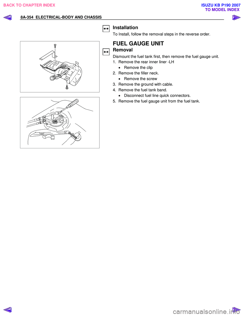
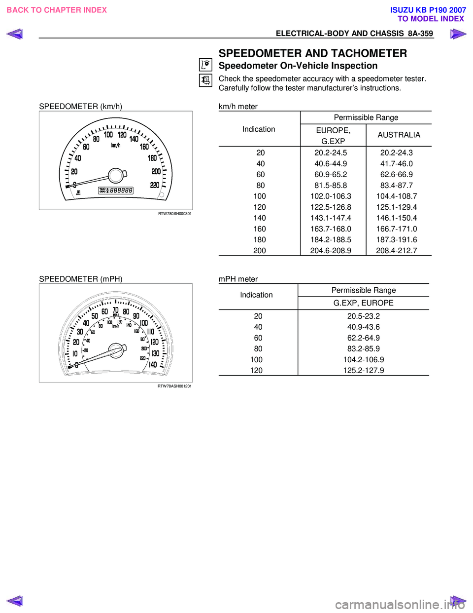
Dismount the fuel tank first, then remove the fuel gauge unit.
1. Remove the rear inner liner -LH
• Remove the clip
2. Remove the filler neck. • Remove the screw
3. Remove the ground with cable.
4. Remove the fuel tank band. • Disconnect fuel line quick connectors.
5. Remove the fuel gauge unit from the fuel tank.
BACK TO CHAPTER INDEX TO MODEL INDEXISUZU KB P190 2007
Page 5293 of 6020
ELECTRICAL-BODY AND CHASSIS 8A-355
Installation
Follow the removal procedure in the reverse order to install the
fuel gauge unit.
Pay close attention to the important points mentioned in the
following paragraphs.
Rubber Seal
Be absolutely sure that the fuel gauge unit rubber seal is
correctly seated.
Connector
Be absolutely sure that the fuel gauge unit connector is
securely connected.
This will prevent a poor contact and an open circuit.
VEHICLE SPEED SENSOR (INSTALLED
ON THE TRANSMISSION)
Removal
1. Disconnect the connector.
2. Remove the vehicle speed sensor body by rotating it.
Installation
To Install, follow the removal steps in the reverse order, noting
the following point.
Tighten the vehicle speed sensor to the specified torque.
Vehicle Speed Sensor Tightening Torque N ⋅m (kg ⋅m/lb.ft)
25 ± 4.9 (2.5 ± 0.5/18 ± 3.6)
BACK TO CHAPTER INDEX TO MODEL INDEXISUZU KB P190 2007
Page 5294 of 6020
8A-356 ELECTRICAL-BODY AND CHASSIS
INSPECTION AND REPAIR
METER AND INDICATOR LIGHT LAYOUT
Without tachometer (4JJ1-TC/4JK1-TC)
RTW 78AMF000501
With tachometer (4JJ1-TC/4JK1-TC)
RTW 78AMF000101
BACK TO CHAPTER INDEX TO MODEL INDEXISUZU KB P190 2007
Page 5295 of 6020
ELECTRICAL-BODY AND CHASSIS 8A-357
Without tachometer (4JA1T(L)/4JH1-TC)
RTW 78AMF000401
With tachometer (4JA1T(L)/4JH1-TC)
RTW 78AMF000201
BACK TO CHAPTER INDEX TO MODEL INDEXISUZU KB P190 2007
Page 5296 of 6020
8A-358 ELECTRICAL-BODY AND CHASSIS
With tachometer (HFV6)
RTW 78AMF000601
Without tachometer (C24SE)
RTW 78AMF000701
BACK TO CHAPTER INDEX TO MODEL INDEXISUZU KB P190 2007
Page 5297 of 6020
ELECTRICAL-BODY AND CHASSIS 8A-359
SPEEDOMETER AND TACHOMETER
Speedometer On-Vehicle Inspection
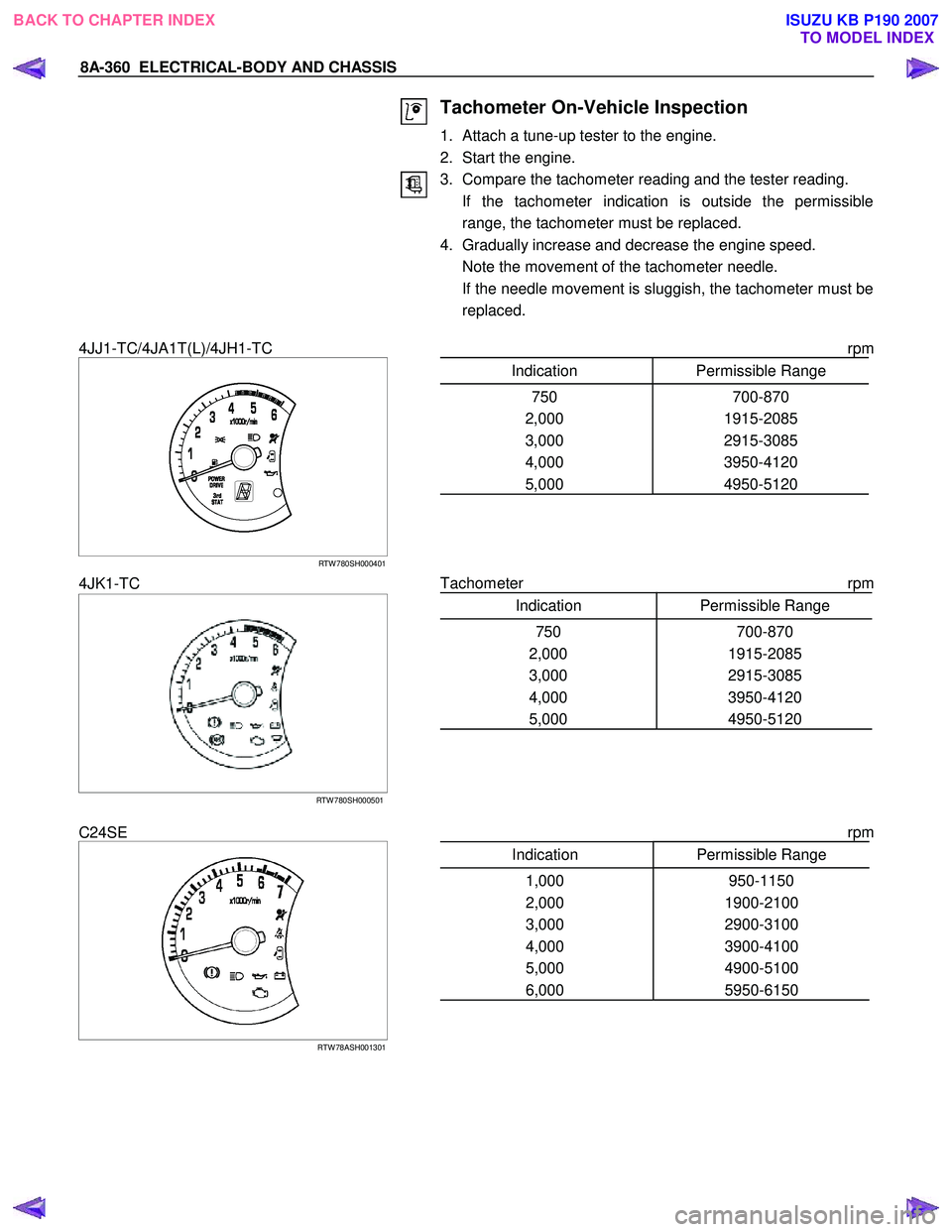
Check the speedometer accuracy with a speedometer tester.
Carefully follow the tester manufacturer’s instructions.
SPEEDOMETER (km/h)
RTW 780SH000301
km/h meter
Permissible Range
Indication EUROPE,
G.EXP AUSTRALIA
20 20.2-24.5 20.2-24.3
40 40.6-44.9 41.7-46.0
60 60.9-65.2 62.6-66.9
80 81.5-85.8 83.4-87.7
100 102.0-106.3 104.4-108.7
120 122.5-126.8 125.1-129.4
140 143.1-147.4 146.1-150.4
160 163.7-168.0 166.7-171.0
180 184.2-188.5 187.3-191.6
200 204.6-208.9 208.4-212.7
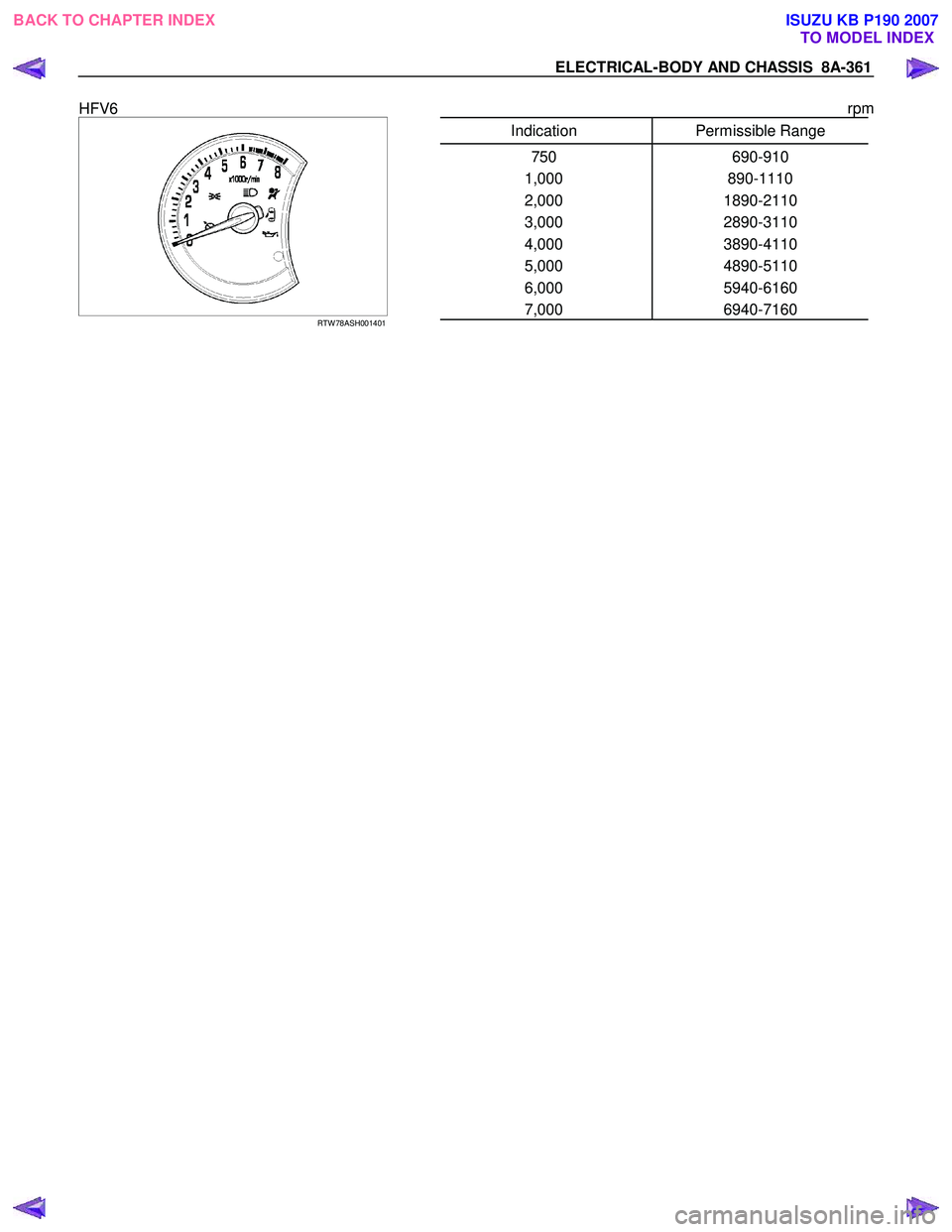
SPEEDOMETER (mPH)
RTW 78ASH001201
mPH meter
Permissible Range
Indication
G.EXP, EUROPE
20 20.5-23.2
40 40.9-43.6
60 62.2-64.9
80 83.2-85.9
100 104.2-106.9
120 125.2-127.9
BACK TO CHAPTER INDEX
TO MODEL INDEXISUZU KB P190 2007
Page 5298 of 6020
8A-360 ELECTRICAL-BODY AND CHASSIS
Tachometer On-Vehicle Inspection
1. Attach a tune-up tester to the engine.
2. Start the engine.
3. Compare the tachometer reading and the tester reading.
If the tachometer indication is outside the permissible range, the tachometer must be replaced.
4. Gradually increase and decrease the engine speed.
Note the movement of the tachometer needle.
If the needle movement is sluggish, the tachometer must be replaced.
4JJ1-TC/4JA1T(L)/4JH1-TC
RTW 780SH000401
rpm
Indication Permissible Range
750 700-870
2,000 1915-2085
3,000 2915-3085
4,000 3950-4120
5,000 4950-5120
4JK1-TC
RTW 780SH000501
Tachometer rpm
Indication Permissible Range
750 700-870
2,000 1915-2085
3,000 2915-3085
4,000 3950-4120
5,000 4950-5120
C24SE
RTW 78ASH001301
rpm
Indication Permissible Range
1,000 950-1150
2,000 1900-2100
3,000 2900-3100
4,000 3900-4100
5,000 4900-5100
6,000 5950-6150
BACK TO CHAPTER INDEX
TO MODEL INDEXISUZU KB P190 2007
Page 5299 of 6020
ELECTRICAL-BODY AND CHASSIS 8A-361
HFV6
RTW 78ASH001401
rpm
Indication Permissible Range
750 690-910
1,000 890-1110
2,000 1890-2110
3,000 2890-3110
4,000 3890-4110
5,000 4890-5110
6,000 5940-6160
7,000 6940-7160
BACK TO CHAPTER INDEX TO MODEL INDEXISUZU KB P190 2007
Page 5300 of 6020

8A-362 ELECTRICAL-BODY AND CHASSIS
Tachometer Off-Vehicle Inspection
Remove the tachometer from the meter assembly and
measure the resistance value and the current consumption
between each terminal.
SELF DIAGNOSTIC FUNCTION
Check that the speedometer, tachometer, fuel gauge, and
temperature gauge operate properly.
821R300033
Entering the self-diagnostic mode
1. Push in and hold the “Change Indicator and Reset” knob.
2. Turn the ignition ON.
3. W hen the LCD odometer turns ON, release the “Change Indicator and Reset” knob.
4. Push in and release the “Change Indicator and Reset” knob three times in quick succession.
The meter cluster is now in “Self-diagnostic” mode.
NOTE: Steps 2-4 must be performed within 7 seconds.
The meter cluster will not enter “Self-diagnostic” mode if any of
the following conditions occur:
1. The “Change Indicator and Reset” knob is not depressed when the ignition is turned ON.
2. The “Change Indicator and Reset” knob is released within 600ms of turning the ignition ON.
3. The “Change Indicator and Reset” knob is not depressed and released three times within 7 seconds.
BACK TO CHAPTER INDEX TO MODEL INDEXISUZU KB P190 2007
Trending: vacuum, spare wheel, Diagram, recommended oil, jump cable, check oil, remote start


