SECURITY ISUZU KB P190 2007 Workshop Manual PDF
[x] Cancel search | Manufacturer: ISUZU, Model Year: 2007, Model line: KB P190, Model: ISUZU KB P190 2007Pages: 6020, PDF Size: 70.23 MB
Page 5518 of 6020

8A-580 ELECTRICAL-BODY AND CHASSIS
TECH-2 OPERATION AND PROGRAMING
KEYLESS ENTRY
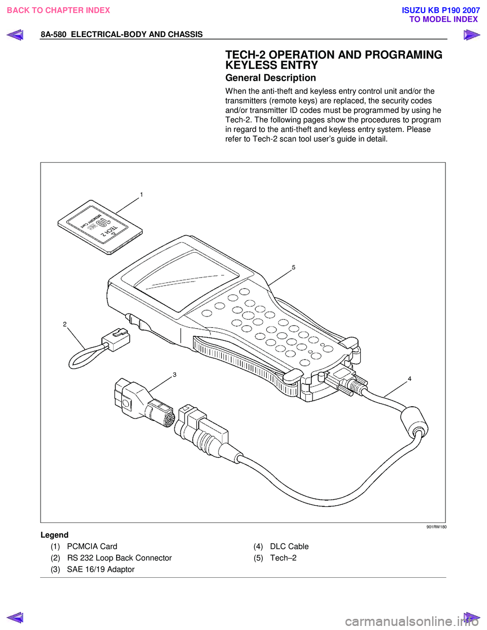
General Description
W hen the anti-theft and keyless entry control unit and/or the
transmitters (remote keys) are replaced, the security codes
and/or transmitter ID codes must be programmed by using he
Tech-2. The following pages show the procedures to program
in regard to the anti-theft and keyless entry system. Please
refer to Tech-2 scan tool user’s guide in detail.
901RW 180
Legend
(1) PCMCIA Card (4) DLC Cable
(2) RS 232 Loop Back Connector (5)Tech–2
(3) SAE 16/19 Adaptor
BACK TO CHAPTER INDEX TO MODEL INDEXISUZU KB P190 2007
Page 5523 of 6020

ELECTRICAL-BODY AND CHASSIS 8A-585
RTW 38DSH001701
Turn Signal Test
Check the turn signal lamp lights up by operation of
Tech-2.
1. Turn the key “OFF”.
2. Turn the key “ON”.
3. Check the display and test menu.
4. Operate the Tech-2.
060R200289
Programming
Erase Remove Key
To erase remove control key code in the control unit.
1. Check the display of Tech-2 and press “Confirm”
key.
RTW 38DSH001001
2. Enter security code.
3. Press “Not Okay” or “Okay” key.
BACK TO CHAPTER INDEX TO MODEL INDEXISUZU KB P190 2007
Page 5851 of 6020

Immobilizer Control System(4jk1/4jj1/hfv6)...................................................................5962 PAGE
Immobilizer System(C24se,4ja1-t)..................................................................................6010
S ection 11B Antitheft System.........................................................................................6066
SECTION 11
TA BLE OF CONTENTS
SECURITY
SECURITY 11-1
TO MODEL INDEX
BACK TO MAIN INDEX
ISUZU KB P190 2007
Page 5859 of 6020

11A-8 IMMOBILIZER CONTROL SYSTEM (4JK1/4JJ1/HFV6)
Diagnostic Information and Procedures
Diagnostic Starting Point - Immobilizer
Controls
Begin the system diagnosis with Diagnostic System
Check - Immobilizer Controls. The Diagnostic System
Check - Immobilizer Controls will provide the following
information:
• The identification of the control modules which command the system.
• The ability of the control modules to communicate through the serial data circuit.
• The identification of any stored diagnostic trouble codes (DTCs) and the their statuses.
The use of the Diagnostic System Check - Immobilizer
Controls will identify the correct procedure for
diagnosing the system and where the procedure is
located.
Diagnostic System Check - Immobilizer
Controls
Description
The Diagnostic System Check - Immobilizer Controls is
an organized approach to identifying a condition that is
created by a malfunction in the electronic immobilizer
control system. The Diagnostic System Check must be
the starting point for any immobilizer system concern.
The Diagnostic System Check directs the service
technician to the next logical step in order to diagnose
the concern. Understanding and correctly using the
diagnostic table reduces diagnostic time, and prevents
the replacement of good parts. Test Description
The numbers below refer to the step numbers on the
diagnostic table.
2. Lack of communication may be because of a partial
or a total malfunction of the serial data circuit.
6. The presence of DTCs which begin with U, indicate
that some other module is not communicating.
9. If there are other modules with DTCs set, refer to the
DTC list. The DTC list directs you to the appropriate
diagnostic procedure.
Important: • DO NOT perform this diagnostic if there is not an immobilizer system concern, unless another
procedure directs you to this diagnostic.
• Before you proceed with diagnosis, search for applicable service bulletins.
• Unless a diagnostic procedure instructs you, DO NOT clear the DTCs.
• Ensure the battery has a full charge.
• Ensure the battery cables (+) (-) are clean and tight.
• Ensure the ICU ground is clean, tight, and in the correct location.
• Ensure the ICU harness connector is clean and correctly connected.
• Ensure the ICU terminals are clean and correctly mating.
• Ensure the immobilizer security information is correctly programmed into the ICU, ECM and PIM.
• Ensure the ICU is correctly installed to the steering lock.
• Ensure objects does not block transponder key in the steering lock.
• Ensure another transponder key is not attached to the key ring.
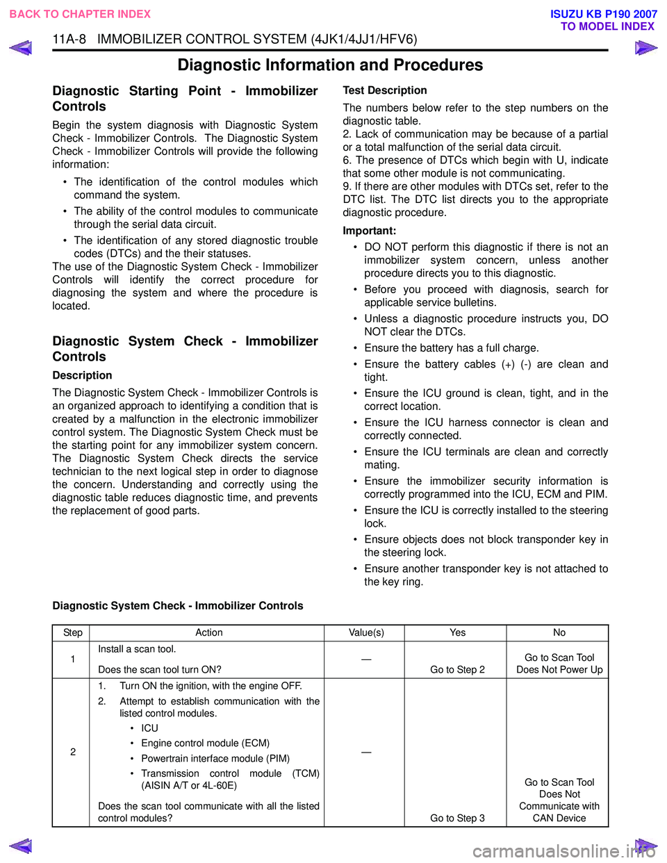
Diagnostic System Check - Immobilizer Controls
Step Action Value(s)Yes No
1 Install a scan tool.
Does the scan tool turn ON? —
Go to Step 2 Go to Scan Tool
Does Not Power Up
2 1. Turn ON the ignition, with the engine OFF.
2. Attempt to establish communication with the listed control modules.
•ICU
• Engine control module (ECM)
• Powertrain interface module (PIM)
• Transmission control module (TCM) (AISIN A/T or 4L-60E)
Does the scan tool communicate with all the listed
control modules? —
Go to Step 3 Go to Scan Tool
Does Not
Communicate with CAN Device
BACK TO CHAPTER INDEX TO MODEL INDEX
ISUZU KB P190 2007
Page 5861 of 6020

11A-10 IMMOBILIZER CONTROL SYSTEM (4JK1/4JJ1/HFV6)
Scan Tool Data List
The Immobilizer Scan Tool Data List contains all
immobilizer related parameters that are available on
the scan tool. Use the Immobilizer Scan Tool Data List
only after the following is determined:
• The Immobilizer Controls - Diagnostic System Check is completed. • On-board diagnostics are functioning properly.
A scan tool that displays faulty data should not be used.
Use of a faulty scan tool can result in misdiagnosis and
unnecessary parts replacement.
Only the parameters listed below are referenced in this
service manual for use in diagnosis.
Scan Tool Data Definitions
This information will assist in immobilizer problems.
Always perform the Diagnostic System Check -
Immobilizer Controls first. The Diagnostic System
Check will confirm proper system operation.
Ignition Status
This parameter displays the state of the ignition switch
input to the ICU. On indicates the ignition switch is
turned ON position.
Transponder Key
This parameter displays the state of the transponder
key in the steering lock. Transponder Key 1 to 5
indicates a correctly programmed transponder key is
used. The number 1 to 5 indicates which transponder
key is used. Invalid indicates an incorrect key is in
used. Not Programmed Key indicates a non-
programmed new transponder key is used. No
Transponder Key indicates ICU does not recognize a
transponder key. Transponder Status
This parameter displays the state of the transponder
key in the steering lock. Correct Transponder-Key
indicates a correctly programmed transponder key is
used. Wrong Transponder-Key indicates an incorrect
key is in used. New Transponder-Key indicates a non-
programmed new transponder key is used. No
Transponder Detected indicates ICU does not
recognize a transponder key.
Transponder-Key 1 to 5 Status
This parameter displays the state of number of
programmed transponder key(s). Programmed
indicates transponder key 1 to 5 is correctly
programmed. The number 1 to 5 indicates programmed
order.
Security Code Programmed
This parameter displays the state of the security code
programming. Yes indicates a security code is correctly
programmed. No indicates a security code is not
programmed.
Scan Tool Parameter Units DisplayedTypical Data Value
Operating Conditions: Ignition switch ON/ Two transponder keys programmed
Ignition Status On/ OffOn
Transponder Key Transponder Key 1 to 5/ Invalid/ Not
Programmed Key/ No Transponder Key Transponder Key 1 or 2
Transponder Status Correct Transponder-Key/ Wrong
Transponder-Key/ New Transponder- Key/ No Transponder Detected Correct Transponder-Key
Transponder-Key 1 Status Programmed/ Not Programmed Programmed
Transponder-Key 2 Status Programmed/ Not Programmed Programmed
Transponder-Key 3 Status Programmed/ Not Programmed Not Programmed
Transponder-Key 4 Status Programmed/ Not Programmed Not Programmed
Transponder-Key 5 Status Programmed/ Not Programmed Not Programmed
Security Code Programmed Yes/ NoYes
Security Wait Time Inactive/ Time (hour: minute: second) Inactive
While Security Lock Inactive/ Active Inactive
BACK TO CHAPTER INDEX
TO MODEL INDEX
ISUZU KB P190 2007
Page 5862 of 6020

IMMOBILIZER CONTROL SYSTEM (4JK1/4JJ1/HFV6) 11A-11
Security Wait Time
This parameter displays the security wait time length in
the ICU. Inactive indicates not in security wait time.
Time indicates under security wait time. This wait time
stage will prevent any further attempts to enter the
security code until the wait time has elapsed. The wait
time will increase each time an incorrect security code
is entered. Note that this parameter is not count
downed. It keeps displaying the same time until that
wait time has elapsed. The ignition switch must be kept
at ON position during the wait time period.
While Security Lock
This parameter displays the state of the security wait
time. Inactive indicates not in security wait time. Active
indicates under security wait time.
BACK TO CHAPTER INDEX TO MODEL INDEX
ISUZU KB P190 2007
Page 5874 of 6020

IMMOBILIZER CONTROL SYSTEM (4JK1/4JJ1/HFV6) 11A-23
DTC B0002
Description
The electrically erasable programmable read only
memory (EEPROM) memorizes immobilizer security
code and transponder key information. If the ICU
detects immobilizer security code is not programmed
into the ICU, this DTC will set.
Condition for Setting the DTC • The ICU detects that the security code is not programmed.
Action Taken When the DTC Sets • The engine will fail to run if the fault occurs before starting the engine. Condition for Clearing the DTC
• A current DTC clears once ignition cycle has occurred without the fault recurring.
• A history DTC will clear after 50 consecutive ignition cycles, if the condition for malfunction is no
longer present.
• Use a scan tool to clear the DTC.
Diagnostic Aids • Non-programmed ICU sets this DTC.
Circuit/ System Testing DTC B0002
Step Action Value(s)Yes No
1 Did you perform the Diagnostic System Check -
Immobilizer Controls? —
Go to Step 2 Go to Diagnostic
System Check - Immobilizer Controls
2 1. Install a scan tool.
2. Turn OFF the ignition for 30 seconds.
3. Turn ON the ignition, with the engine OFF.
4. Monitor the DTC Information with a scan tool.
Does the DTC fail this ignition? —
Go to Step 3 Go to Diagnostic
Aids
3 Program immobilizer security information into the
ICU. Refer to Resetting and Programming
Guidelines in this section.
Did you complete the programming? —
Go to Step 4
—
41. Clear the DTCs with a scan tool.
2. Turn OFF the ignition for 30 seconds.
3. Turn ON the ignition.
Did the DTC fail this ignition? —
Go to Step 3 Go to Step 5
5 Observe the DTC Information with a scan tool.
Are there any DTCs that you have not diagnosed? —
Go to DTC List System OK
BACK TO CHAPTER INDEX
TO MODEL INDEX
ISUZU KB P190 2007
Page 5880 of 6020

IMMOBILIZER CONTROL SYSTEM (4JK1/4JJ1/HFV6) 11A-29
DTC B0009
Description
The electrically erasable programmable read only
memory (EEPROM) memorizes immobilizer security
code and transponder key information. If the ICU
detects any transponder key is not programmed into
the ICU, this DTC will set.
Condition for Running the DTC • The ignition switch is ON.
Condition for Setting the DTC • The ICU detects any transponder key is not programmed. Action Taken When the DTC Sets
• The engine will fail to run if the fault occurs before starting the engine.
Condition for Clearing the DTC • A current DTC clears once ignition cycle has occurred without the fault recurring.
• A history DTC will clear after 50 consecutive ignition cycles, if the condition for malfunction is no
longer present.
• Use a scan tool to clear the DTC.
Circuit/ System Testing DTC B0009
Step Action Value(s)Yes No
1 Did you perform the Diagnostic System Check -
Immobilizer Controls? —
Go to Step 2 Go to Diagnostic
System Check - Immobilizer Controls
2 1. Install a scan tool.
2. Turn OFF the ignition for 30 seconds.
3. Turn ON the ignition, with the engine OFF.
4. Monitor the DTC Information with a scan tool.
Is DTC B0002 also set? —
Go to DTC B0002 Go to Step 3
3 Program transponder key information into the ICU.
Refer to Resetting and Programming Guidelines in
this section.
Did you complete the programming? —
Go to Step 4
—
41. Clear the DTCs with a scan tool.
2. Turn OFF the ignition for 30 seconds.
3. Turn ON the ignition.
Did the DTC fail this ignition? —
Go to Step 3 Go to Step 5
5 Observe the DTC Information with a scan tool.
Are there any DTCs that you have not diagnosed? —
Go to DTC List System OK
BACK TO CHAPTER INDEX
TO MODEL INDEX
ISUZU KB P190 2007
Page 5885 of 6020

11A-34 IMMOBILIZER CONTROL SYSTEM (4JK1/4JJ1/HFV6)
DTC B0014
Description
When the transponder key authentication is completed,
the ICU begins authentication of the ECM. The ECM
transmits a specific request signal to the ICU and the
ICU sends back a response signal to the ECM. Both
communication signals are carried out via a controller
area network (CAN) communication bus. If the ICU
receives a wrong request signal from the ECM, this
DTC will set.
Condition for Running the DTC • The ignition switch is ON.
Condition for Setting the DTC • The ICU detects a wrong request signal from the ECM. Action Taken When the DTC Sets
• The engine will fail to run if the fault occurs before starting the engine.
Condition for Clearing the DTC • A current DTC clears once ignition cycle has occurred without the fault recurring.
• A history DTC will clear after 50 consecutive ignition cycles, if the condition for malfunction is no
longer present.
• Use a scan tool to clear the DTC.
Diagnostic Aids • Non-programmed ECM may set this DTC.
• If the ECM is transferred (swapped) from another vehicle, this DTC will set.
Circuit/ System Testing DTC B0014
Step Action Value(s)Yes No
1 Did you perform the Diagnostic System Check -
Immobilizer Controls? —
Go to Step 2 Go to Diagnostic
System Check - Immobilizer
Controls
2 1. Install a scan tool.
2. Turn OFF the ignition for 30 seconds.
3. Turn ON the ignition, with the engine OFF.
4. Monitor the DTC Information with a scan tool.
Does the DTC fail this ignition? —
Go to Step 3 Go to Diagnostic
Aids
3 Program immobilizer security information into the
ECM. Refer to Resetting and Programming
Guidelines in this section.
Did you complete the programming? —
Go to Step 4
—
41. Clear the DTCs with a scan tool.
2. Turn OFF the ignition for 30 seconds.
3. Turn ON the ignition.
Did the DTC fail this ignition? —
Go to Step 3 Go to Step 5
5 Observe the DTC Information with a scan tool.
Are there any DTCs that you have not diagnosed? —
Go to DTC List System OK
BACK TO CHAPTER INDEX
TO MODEL INDEX
ISUZU KB P190 2007
Page 5887 of 6020

11A-36 IMMOBILIZER CONTROL SYSTEM (4JK1/4JJ1/HFV6)
Resetting and Programming
Resetting and Programming Guidelines
Notice:The security information must be programmed
when the ICU, ECM, PIM or transponder key(s) is
replaced, or transponder key(s) is added.
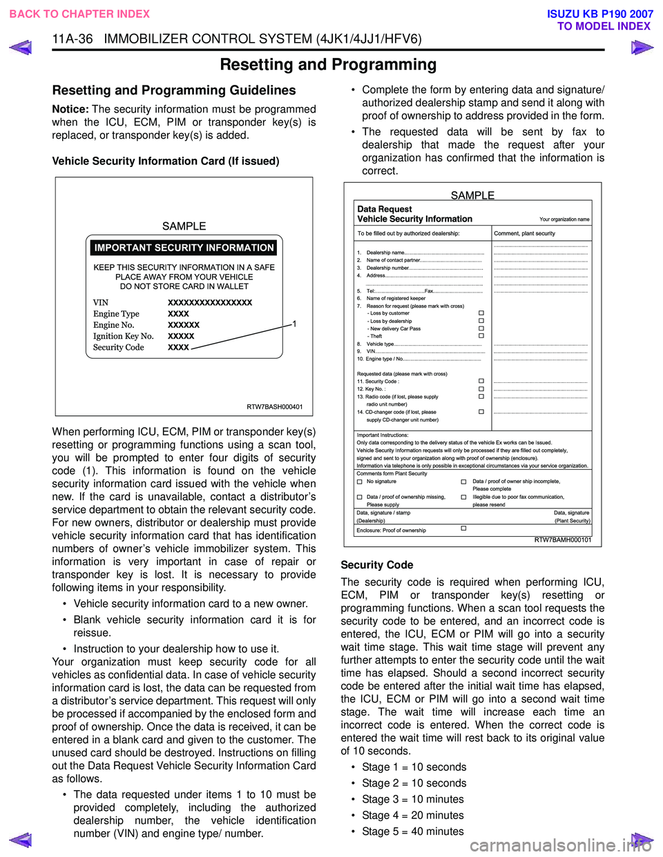
Vehicle Security Information Card (If issued)
When performing ICU, ECM, PIM or transponder key(s)
resetting or programming functions using a scan tool,
you will be prompted to enter four digits of security
code (1). This information is found on the vehicle
security information card issued with the vehicle when
new. If the card is unavailable, contact a distributor’s
service department to obtain the relevant security code.
For new owners, distributor or dealership must provide
vehicle security information card that has identification
numbers of owner’s vehicle immobilizer system. This
information is very important in case of repair or
transponder key is lost. It is necessary to provide
following items in your responsibility.
• Vehicle security information card to a new owner.
• Blank vehicle security information card it is for reissue.
• Instruction to your dealership how to use it.
Your organization must keep security code for all
vehicles as confidential data. In case of vehicle security
information card is lost, the data can be requested from
a distributor’s service department. This request will only
be processed if accompanied by the enclosed form and
proof of ownership. Once the data is received, it can be
entered in a blank card and given to the customer. The
unused card should be destroyed. Instructions on filling
out the Data Request Vehicle Security Information Card
as follows.
• The data requested under items 1 to 10 must be provided completely, including the authorized
dealership number, the vehicle identification
number (VIN) and engine type/ number. • Complete the form by entering data and signature/
authorized dealership stamp and send it along with
proof of ownership to address provided in the form.
• The requested data will be sent by fax to dealership that made the request after your
organization has confirmed that the information is
correct.
Security Code
The security code is required when performing ICU,
ECM, PIM or transponder key(s) resetting or
programming functions. When a scan tool requests the
security code to be entered, and an incorrect code is
entered, the ICU, ECM or PIM will go into a security
wait time stage. This wait time stage will prevent any
further attempts to enter the security code until the wait
time has elapsed. Should a second incorrect security
code be entered after the initial wait time has elapsed,
the ICU, ECM or PIM will go into a second wait time
stage. The wait time will increase each time an
incorrect code is entered. When the correct code is
entered the wait time will rest back to its original value
of 10 seconds.
• Stage 1 = 10 seconds
• Stage 2 = 10 seconds
• Stage 3 = 10 minutes
• Stage 4 = 20 minutes
• Stage 5 = 40 minutes
RTW7BASH000401
KEEP THIS SECURITY INFORMATION IN A SAFE PLACE AWAY FROM YOUR VEHICLEDO NOT STORE CARD IN WALLET
1
SAMPLE
RTW7BAMH000101
Your organization name
To be filled out by authorized dealership: Comment, plant security
1. Dealership name.......................................................... ....................................................................
....................................................................
....................................................................
....................................................................
....................................................................
....................................................................
....................................................................
....................................................................
.................................................................... ....................................................................
....................................................................
....................................................................
....................................................................
....................................................................
2. Name of contact partner.............................................
6. Name of registered keeper
7. Reason for request (please mark with cross)
3. Dealership number......................................................
4. Address.......................................................................
8. Vehicle type................................................................
9. VIN................................................................................
10. Engine type / No.........................................................
11. Security Code :
12. Key No. :
13. Radio code (if lost, please supply radio unit number)
14. CD-changer code (if lost, please
supply CD-changer unit number)
Requested data (please mark with cross)
5. Tel:....................................Fax....................................
.....................................................................................
- Loss by customer
- Loss by dealership
- New delivery Car Pass
- Theft
Important Instructions:
Comments form Plant Security
Data, signature / stamp Data, signature
(Dealership) (Plant Security)
Enclosure: Proof of ownership Only data corresponding to the delivery status of the vehicle Ex works can be Issued.
Vehicle Security Information requests will only be processed if they are filled out completely,
signed and sent to your organization along with proof of ownership (enclosure).
Information via telephone is only possible in exceptional circumstances via your service organization.
No signature Data / proof of owner ship incomplete,
Please complete
Data / proof of ownership missing,
Please supply Illegible due to poor fax communication,
please resend
SAMPLE
BACK TO CHAPTER INDEX TO MODEL INDEX
ISUZU KB P190 2007