Wiring harness ISUZU KB P190 2007 Workshop Manual PDF
[x] Cancel search | Manufacturer: ISUZU, Model Year: 2007, Model line: KB P190, Model: ISUZU KB P190 2007Pages: 6020, PDF Size: 70.23 MB
Page 2788 of 6020

Engine Mechanical – V6 Page 6A1–11
Page 6A1–11
Intake Manifold Assembly
Figure 6A1 – 3
Legend
1 PCV Hose
2 PCV Hose O-Ring Outer (larger)
3 PCV Hose O-Ring Inner (smaller)
4 Upper Intake Manifold
5 Lower Intake Manifold
6 Upper Intake Manifold Bolt – Long
7 Upper Intake Manifold Bolt – Short
8 Lower Intake Manifold to Upper Intake Manifold Guide Pin
9 Upper Intake Manifold to Lower Intake Manifold Gasket
10 Lower Intake Manifold to Cylinder Head Gasket
11 Lower Intake Manifold Bolt
12 Fuel Rail Bolt
13 Fuel Rail
14 Fuel Injector
15 Fuel Injector Retainer
16 Fuel Injector Upper O-ring 17 Fuel Injector Lower O-ring
18 Fuel Pressure Service Valve Cap
19 Fuel Pressure Service Valve
20 Ball Stud
21 Fuel Injector Wiring Harness
22 Throttle Body
23 Throttle Body Bolt
24 Throttle Body Gasket
25 Throttle Body Engine Wiring Harness Clip
26 EVAP Purge Solenoid
27 EVAP Purge Solenoid Bolt
28 EVAP Purge Solenoid Tube
29 EVAP Purge Solenoid Bracket
30 BARO Sensor Bolt
31 BARO Sensor
32 BARO Sensor O-Ring
BACK TO CHAPTER INDEX
TO MODEL INDEX
ISUZU KB P190 2007
Page 2847 of 6020
Engine Mechanical – V6 Page 6A1–70
Page 6A1–70
3.3 Oil Filter Adaptor
Remove
Disconnection of the battery affects
certain vehicle electronic systems, refer to
1.1 WARNING, CAUTION and NOTES before
disconnecting the battery.
1 Disconnect the battery negative terminal.
2 Disconnect the wiring harness connecto r from the oil pressure sender.
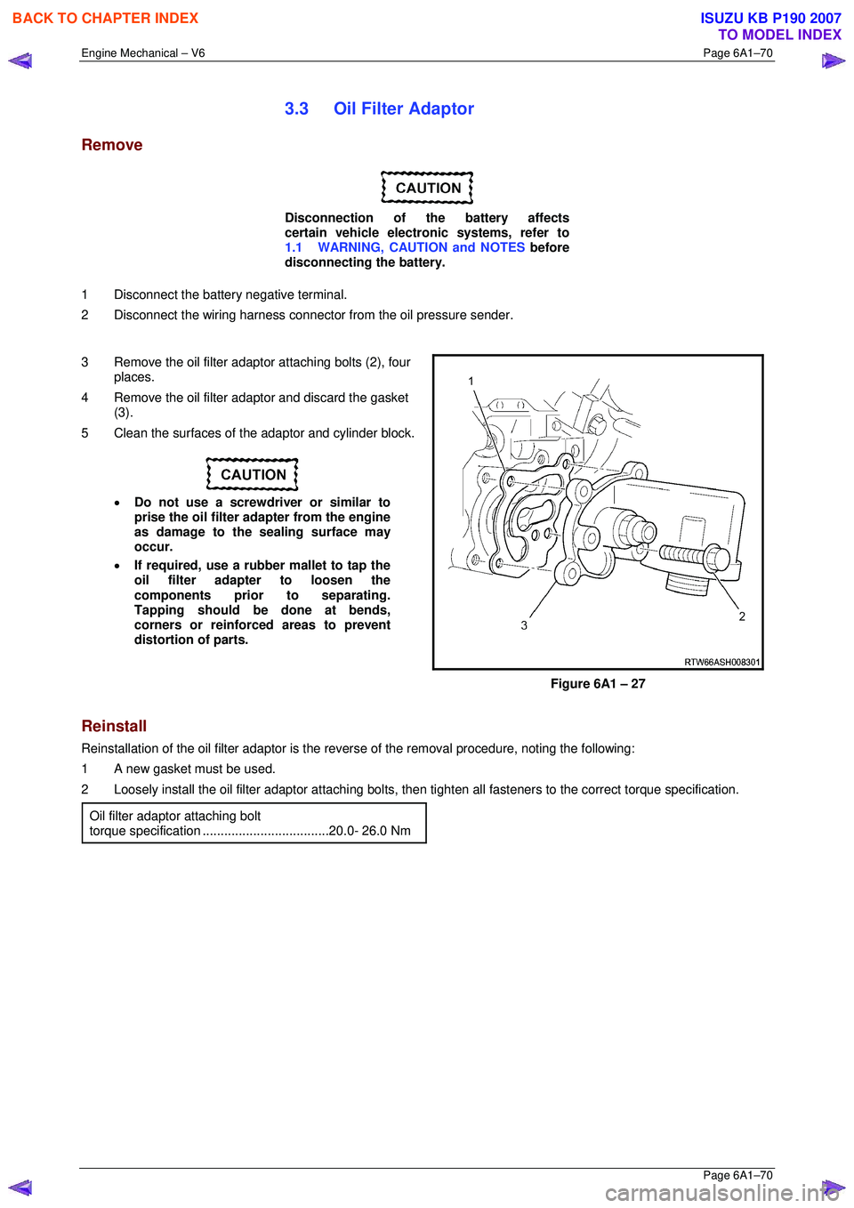
3 Remove the oil filter adaptor attaching bolts (2), four
places.
4 Remove the oil filter adaptor and discard the gasket (3).
5 Clean the surfaces of t he adaptor and cylinder block.
• Do not use a screwdriver or similar to
prise the oil filter adapter from the engine
as damage to the sealing surface may
occur.
• If required, use a rubber mallet to tap the
oil filter adapter to loosen the
components prior to separating.
Tapping should be done at bends,
corners or reinforced areas to prevent
distortion of parts.
Figure 6A1 – 27
Reinstall
Reinstallation of the oil filter adaptor is the reverse of the remo val procedure, noting the following:
1 A new gasket must be used.
2 Loosely install the oil filter adaptor attaching bolts, then tighten all fast eners to the correct torque specification.
Oil filter adaptor attaching bolt
torque specificatio n ...................................20.0- 26.0 Nm
BACK TO CHAPTER INDEX
TO MODEL INDEX
ISUZU KB P190 2007
Page 2848 of 6020
Engine Mechanical – V6 Page 6A1–71
Page 6A1–71
3.4 Oil Level Indicator Tube
Remove
1 Remove the oil level indicator from the oil level indicator tube.
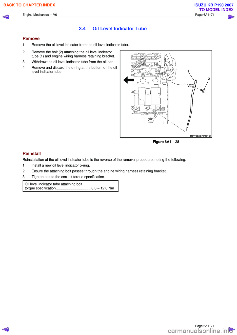
2 Remove the bolt (2) attaching the oil level indicator tube (1) and engine wiring harness retaining bracket.
3 Withdraw the oil level indi cator tube from the oil pan.
4 Remove and discard the o-ring at the bottom of the oil level indicator tube.
Figure 6A1 – 28
Reinstall
Reinstallation of the oil level indicator tube is the reverse of the removal procedure, noting the following:
1 Install a new oil level indicator o-ring.
2 Ensure the attaching bolt passes through the engine wiring harness retaining bracket.
3 Tighten bolt to the correct torque specification.
Oil level indicator tube attaching bolt
torque specificatio n ................................... 8. 0 – 12.0 Nm
BACK TO CHAPTER INDEX
TO MODEL INDEX
ISUZU KB P190 2007
Page 2855 of 6020
Engine Mechanical – V6 Page 6A1–78
Page 6A1–78
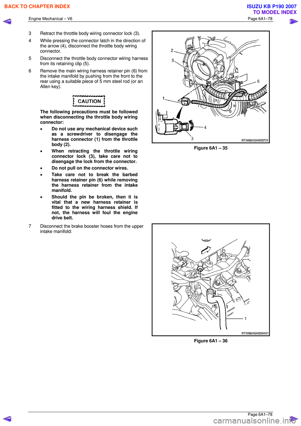
3 Retract the throttle body wiring connector lock (3).
4 While pressing the connector latch in the direction of
the arrow (4), disconnect the throttle body wiring
connector.
5 Disconnect the throttle body connector wiring harness from its retaining clip (5).
6 Remove the main wiring harness retainer pin (6) from the intake manifold by pushing from the front to the
rear using a suitable piece of 5 mm steel rod (or an
Allen key).
The following precautions must be followed
when disconnecting the throttle body wiring
connector:
• Do not use any mechanical device such
as a screwdriver to disengage the
harness connector (1) from the throttle
body (2).
• When retracting the throttle wiring
connector lock (3), take care not to
disengage the lock from the connector.
• Do not pull on the connector wires.
• Take care not to break the barbed
harness retainer pin (6) while removing
the harness retainer from the intake
manifold.
• Should the pin be broken, then it is
vital that a new harness retainer is
fitted to the wiring harness shield. If
not, the harness will foul the engine
drive belt.
Figure 6A1 – 35
7 Disconnect the brake booster hoses from the upper intake manifold:
Figure 6A1 – 36
BACK TO CHAPTER INDEX
TO MODEL INDEX
ISUZU KB P190 2007
Page 2856 of 6020

Engine Mechanical – V6 Page 6A1–79
Page 6A1–79
8 Disconnect the wiring harness connector from the
barometric (BARO) pressure sensor (1).
Figure 6A1 – 37
9 Disconnect the PCV tube connector (1) from the upper intake manifold assembly.
Figure 6A1 – 38
10 Remove the bolt (3) attaching the EVAP valve and the fuel injector wiring harness connector mounting
bracket to the upper inta ke manifold assembly.
11 Move the EVAP valve and the fuel injector wiring harness connector mounting br acket clear of the upper
intake manifold assembly.
12 Disconnect the PCV fresh air tube (1) from its upper intake manifold mounting clip (2).
Figure 6A1 – 39
BACK TO CHAPTER INDEX
TO MODEL INDEX
ISUZU KB P190 2007
Page 2859 of 6020
Engine Mechanical – V6 Page 6A1–82
Page 6A1–82
Reinstall
Reinstallation of the upper intake manifold and the upper and lower intake manifold assembly is the reverse of the
removal procedure, noting the following:
1 Only new gaskets are to be fitted betw een the upper and lower intake manifolds.
CAUTION
Tighten the intake manifold bolts in a circular
pattern starting at the centre bolt and moving
outward.
2 Ensure that all fasteners are tightened to the correct torque specification.
Upper intake manifold to lower
intake manifold attaching bolt
torque specificat ion ............................................ 23.0 Nm
Upper intake manifold to
cylinder head attaching bolt
torque specification ............................................ 23.0 Nm
Incorrect wiring connector installation may
cause component malfunction or component
damage.
3 Ensure all wiring connectors are fully engaged and if applicable, locked in place.
4 Ensure all wiring harnesses are correctly routed and attached securely in their retaining clips.
5 Ensure that all hoses and pipes ar e routed correctly and that any retaining clips are correctly installed.
6 Start and run the engine to c heck for correct operation.
BACK TO CHAPTER INDEX
TO MODEL INDEX
ISUZU KB P190 2007
Page 2861 of 6020
Engine Mechanical – V6 Page 6A1–84
Page 6A1–84
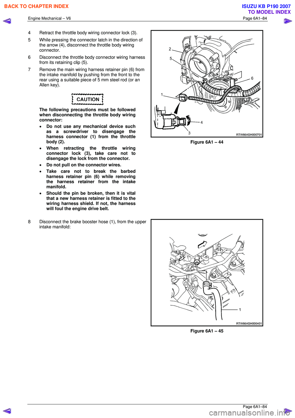
4 Retract the throttle body wiring connector lock (3).
5 While pressing the connector latch in the direction of
the arrow (4), disconnect the throttle body wiring
connector.
6 Disconnect the throttle body connector wiring harness from its retaining clip (5).
7 Remove the main wiring harness retainer pin (6) from the intake manifold by pushing from the front to the
rear using a suitable piece of 5 mm steel rod (or an
Allen key).
The following precautions must be followed
when disconnecting the throttle body wiring
connector:
• Do not use any mechanical device such
as a screwdriver to disengage the
harness connector (1) from the throttle
body (2).
• When retracting the throttle wiring
connector lock (3), take care not to
disengage the lock from the connector.
• Do not pull on the connector wires.
• Take care not to break the barbed
harness retainer pin (6) while removing
the harness retainer from the intake
manifold.
• Should the pin be broken, then it is vital
that a new harness retainer is fitted to the
wiring harness shield. If not, the harness
will foul the engine drive belt.
Figure 6A1 – 44
8 Disconnect the brake booster hose (1), from the upper
intake manifold:
Figure 6A1 – 45
BACK TO CHAPTER INDEX
TO MODEL INDEX
ISUZU KB P190 2007
Page 2862 of 6020

Engine Mechanical – V6 Page 6A1–85
Page 6A1–85
9 Disconnect the wiring harness connector from the
barometric (BARO) pressure sensor (1).
Figure 6A1 – 46
10 Disconnect the PCV tube connector (1) from the upper intake manifold assembly.
Figure 6A1 – 47
11 Disconnect the fuel feed hose from the fuel rail (1).
12 Pull out the release bar (2) (broad arrow) of the fuel
injector harness wiring connector (3).
13 Disconnect the fuel injector harness wiring connector from the fuel injector wiring harness (4).
Plug the fuel feed hose opening after
removal to prevent dirt and other
contaminants from entering the fuel system.
Figure 6A1 – 48
BACK TO CHAPTER INDEX
TO MODEL INDEX
ISUZU KB P190 2007
Page 2863 of 6020
Engine Mechanical – V6 Page 6A1–86
Page 6A1–86
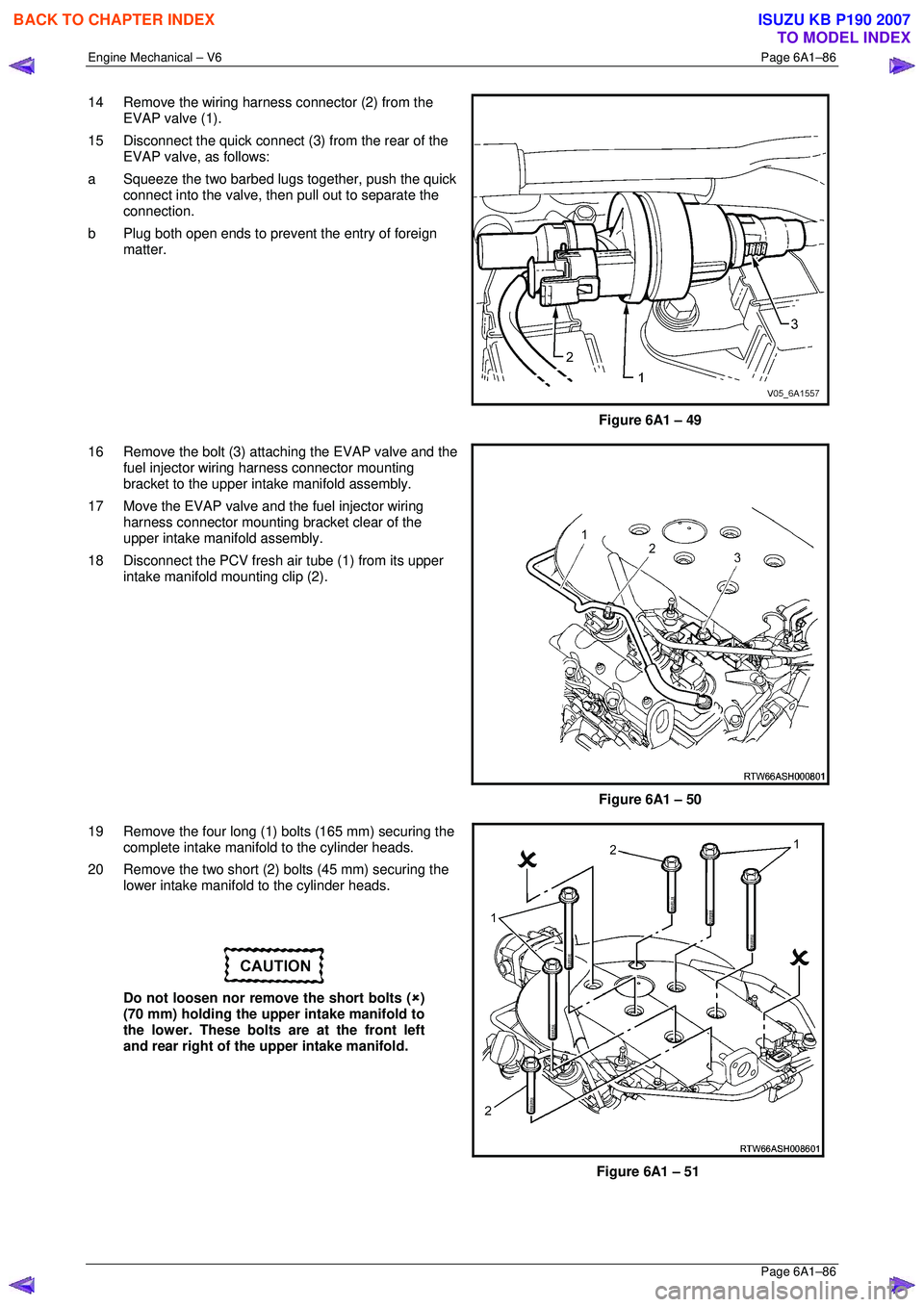
14 Remove the wiring harness connector (2) from the
EVAP valve (1).
15 Disconnect the quick connect (3 ) from the rear of the
EVAP valve, as follows:
a Squeeze the two barbed lugs together, push the quick
connect into the valve, t hen pull out to separate the
connection.
b Plug both open ends to prevent the entry of foreign
matter.
Figure 6A1 – 49
16 Remove the bolt (3) attaching the EVAP valve and the fuel injector wiring harness connector mounting
bracket to the upper inta ke manifold assembly.
17 Move the EVAP valve and the fuel injector wiring harness connector mounting bracket clear of the
upper intake manifold assembly.
18 Disconnect the PCV fresh air tube (1) from its upper intake manifold mounting clip (2).
Figure 6A1 – 50
19 Remove the four long (1) bolts (165 mm) securing the complete intake manifo ld to the cylinder heads.
20 Remove the two short (2) bolts (45 mm) securing the lower intake manifold to the cylinder heads.
Do not loosen nor remove the short bolts ( �8)
(70 mm) holding the upper intake manifold to
the lower. These bolts are at the front left
and rear right of the upper intake manifold.
Figure 6A1 – 51
BACK TO CHAPTER INDEX
TO MODEL INDEX
ISUZU KB P190 2007
Page 2866 of 6020
Engine Mechanical – V6 Page 6A1–89
Page 6A1–89
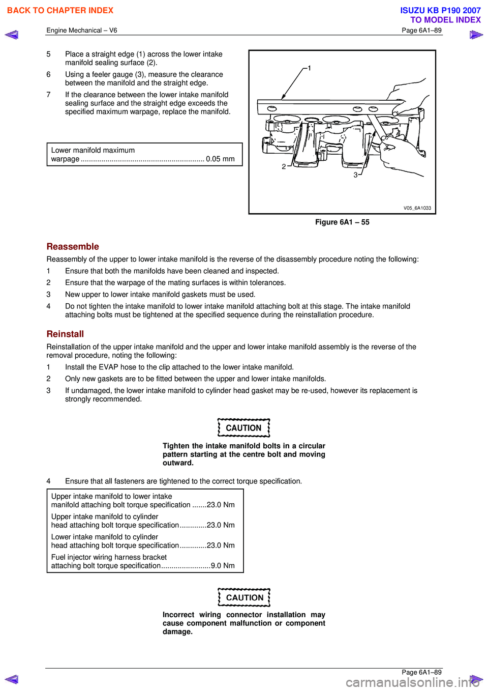
5 Place a straight edge (1) across the lower intake
manifold sealing surface (2).
6 Using a feeler gauge (3), measure the clearance
between the manifold and the straight edge.
7 If the clearance between the lower intake manifold sealing surface and the straight edge exceeds the
specified maximum warpage, replace the manifold.
Lower manifold maximum
warpage ............................................................ 0.05 mm
Figure 6A1 – 55
Reassemble
Reassembly of the upper to lower intake manifold is the reverse of the disassembly procedure noting the following:
1 Ensure that both the manifo lds have been cleaned and inspected.
2 Ensure that the warpage of the mati ng surfaces is within tolerances.
3 New upper to lower intake m anifold gaskets must be used.
4 Do not tighten the intake manifold to lower intake manifold attaching bolt at this stage. The intake manifold
attaching bolts must be tightened at the specif ied sequence during the reinstallation procedure.
Reinstall
Reinstallation of the upper intake manifold and the upper and lower intake manifo ld assembly is the reverse of the
removal procedure, noting the following:
1 Install the EVAP hose to the clip atta ched to the lower intake manifold.
2 Only new gaskets are to be fitted betw een the upper and lower intake manifolds.
3 If undamaged, the lower intake manifold to cylinder head gasket may be re-used, however its replacement is
strongly recommended.
CAUTION
Tighten the intake manifold bolts in a circular
pattern starting at the centre bolt and moving
outward.
4 Ensure that all fasteners are tightened to the correct torque specification.
Upper intake manifold to lower intake
manifold attaching bolt torq ue specification .......23.0 Nm
Upper intake manifold to cylinder
head attaching bolt torque specification .............23.0 Nm
Lower intake manifold to cylinder
head attaching bolt torque specification .............23.0 Nm
Fuel injector wiring harness bracket
attaching bolt torque specification ........................9.0 Nm
Incorrect wiring connector installation may
cause component malfunction or component
damage.
BACK TO CHAPTER INDEX
TO MODEL INDEX
ISUZU KB P190 2007