Wiring harness ISUZU KB P190 2007 Workshop Manual Online
[x] Cancel search | Manufacturer: ISUZU, Model Year: 2007, Model line: KB P190, Model: ISUZU KB P190 2007Pages: 6020, PDF Size: 70.23 MB
Page 2867 of 6020

Engine Mechanical – V6 Page 6A1–90
Page 6A1–90
5 Ensure all wiring connectors are fully engaged and if applicable, locked in place.
6 Ensure all wiring harnesses are correctly routed and attached securely in their retaining clips.
7 Ensure that all hoses and pipes ar e routed correctly and that any retaining clips are correctly installed.
8 After installation pull on any quick connect fittings to check that each is correctly installed.
9 Start and run the engine to c heck for correct operation.
BACK TO CHAPTER INDEX
TO MODEL INDEX
ISUZU KB P190 2007
Page 2868 of 6020

Engine Mechanical – V6 Page 6A1–91
Page 6A1–91
3.11 Exhaust Manifold Assembly
Remove
Allow the engine to cool before commencing.
Disconnection of the battery affects
certain vehicle electronic systems, refer to
1.1 WARNING, CAUTION and NOTES before
disconnecting the battery.
1 Disconnect the battery negative terminal.
2 Remove the oxygen sensor harness connector (1) from the retaining bracket.
3 Disconnect the oxygen sensor wiring harness connector from the engine wiring harness connector
(2).
4 Unclip the oxygen sensor wiring harness retaining clip and move aside.
5 For the left-hand side: Remove the oil level indicator tube.
6 Raise the front of the vehicle and place on stands,
refer to Section 0A General Information .
7 Working from under the vehicle, remove the two exhaust manifold to exhaust pipe flange nuts, refer to
Section 6F Exhaust System - V6 .
Figure 6A1 – 56
8 Remove the three bolts attaching the exhaust manifold outer heat shield (1) to the exhaust manifold
(2).
Figure 6A1 – 57
BACK TO CHAPTER INDEX
TO MODEL INDEX
ISUZU KB P190 2007
Page 2871 of 6020

Engine Mechanical – V6 Page 6A1–94
Page 6A1–94
3.12 Camshaft Cover
Remove
1 Remove the intake manifold assembly, refer to 3.10 Intake Manifold Assembly – Complete .
2 For the left-hand side, remove the evaporative (EVAP) emission canister purge solenoid, refer to Section 6C1-3 Engine Management – V6 – Service Operations.
3 Remove the two bolts (1) attaching the engine wiring harness former to the rear of the cylinder heads.
4 Unclip the transmission v ent tube (2) from the engine
wiring harness.
Figure 6A1 – 61
5 Disconnect the oxygen sensor wiring harness connector (1) from the engine wiring harness (2), left-
hand shown, right-hand similar.
Figure 6A1 – 62
BACK TO CHAPTER INDEX
TO MODEL INDEX
ISUZU KB P190 2007
Page 2872 of 6020

Engine Mechanical – V6 Page 6A1–95
Page 6A1–95
6 Remove the bolt (1) attaching the ground connector
(2) to the cylinder head.
7 Fro the left-hand side, disconnect the engine coolant temperature (ECT) sensor wiring connector (3).
8 Unclip the engine wiring harness retaining lugs from the side of the camshaft cover.
Figure 6A1 – 63
9 For the right-hand side, remove the engine wiring harness retaining clip (1) from the engine control
module (ECM) bracket (2).
Figure 6A1 – 64
10 Disconnect the camshaft position (CMP) sensor wiring connector (1).
11 Unclip the engine wiring harness retaining lug (3) from the front of the camshaft cover.
12 Remove the ignition coil assemblies; refer to Section 6C1-3 Engine Management – V6 – Service
Operations .
13 Move the engine wiring harness clear of the camshaft cover.
Figure 6A1 – 65
BACK TO CHAPTER INDEX
TO MODEL INDEX
ISUZU KB P190 2007
Page 2876 of 6020

Engine Mechanical – V6 Page 6A1–99
Page 6A1–99
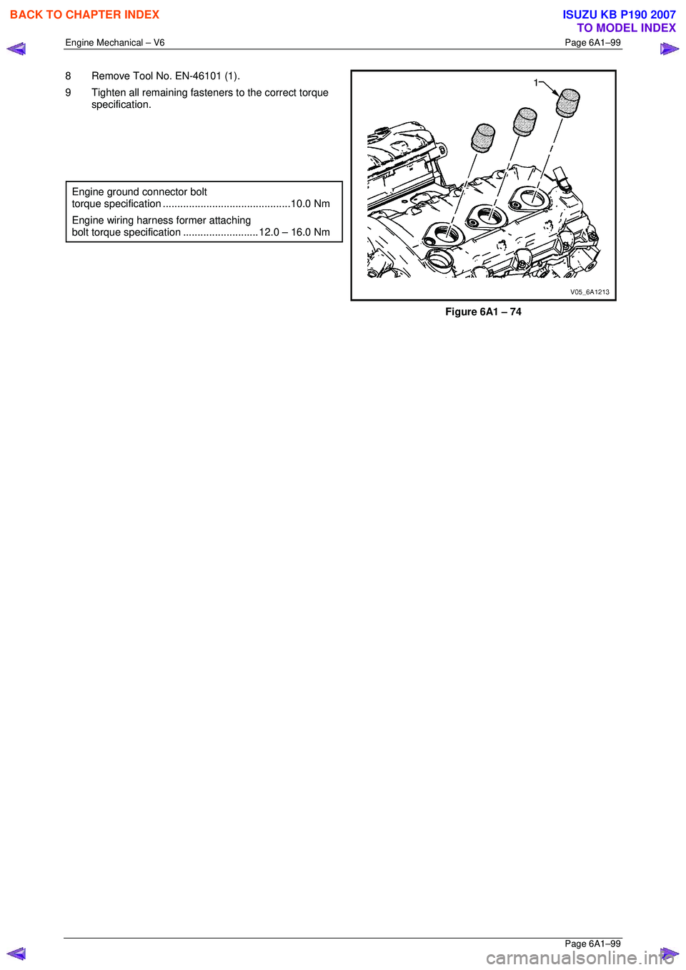
8 Remove Tool No. EN-46101 (1).
9 Tighten all remaining fasteners to the correct torque specification.
Engine ground connector bolt
torque specificat ion ............................................ 10.0 Nm
Engine wiring harness former attaching
bolt torque specification .......................... 12.0 – 16.0 Nm
Figure 6A1 – 74
BACK TO CHAPTER INDEX
TO MODEL INDEX
ISUZU KB P190 2007
Page 3019 of 6020

Engine Mechanical – V6 Page 6A1–242
Page 6A1–242
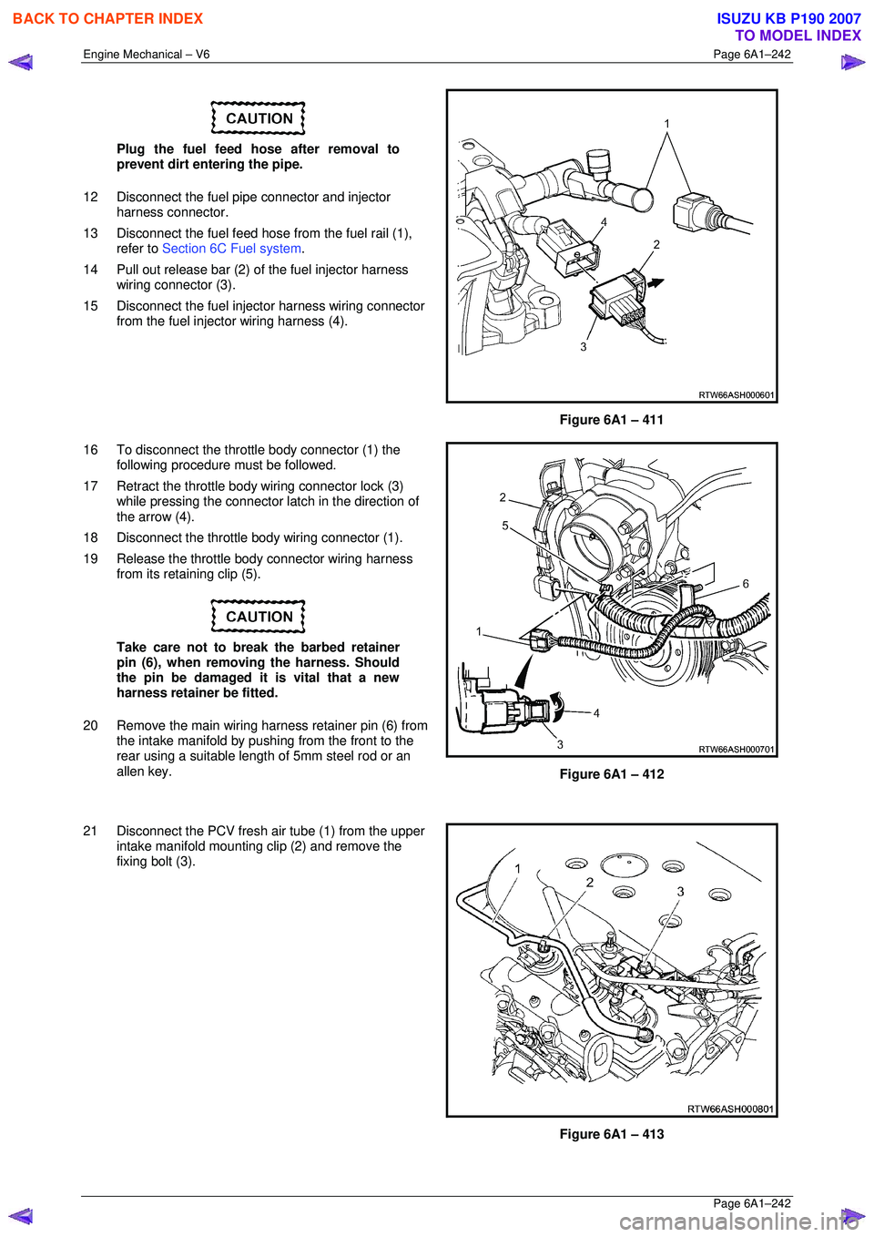
Plug the fuel feed hose after removal to
prevent dirt entering the pipe.
12 Disconnect the fuel pipe connector and injector harness connector.
13 Disconnect the fuel feed hose from the fuel rail (1),
refer to Section 6C Fuel system .
14 Pull out release bar (2) of the fuel injector harness
wiring connector (3).
15 Disconnect the fuel injector harness wiring connector from the fuel injector wiring harness (4).
Figure 6A1 – 411
16 To disconnect the throttle body connector (1) the following procedure must be followed.
17 Retract the throttle body wiring connector lock (3) while pressing the connector la tch in the direction of
the arrow (4).
18 Disconnect the throttle body wiring connector (1).
19 Release the throttle body connector wiring harness from its retaining clip (5).
Take care not to break the barbed retainer
pin (6), when removing the harness. Should
the pin be damaged it is vital that a new
harness retainer be fitted.
20 Remove the main wiring harness retainer pin (6) from the intake manifold by pushing from the front to the
rear using a suitable lengt h of 5mm steel rod or an
allen key.
Figure 6A1 – 412
21 Disconnect the PCV fresh air tube (1) from the upper intake manifold mounting clip (2) and remove the
fixing bolt (3).
Figure 6A1 – 413
BACK TO CHAPTER INDEX
TO MODEL INDEX
ISUZU KB P190 2007
Page 3021 of 6020

Engine Mechanical – V6 Page 6A1–244
Page 6A1–244
28 Remove the centre exhaust pipe (1), refer to
Section 6F Exhaust System - V6 .
Figure 6A1 – 417
29 Disconnect the two post-catalytic converter oxygen sensor wiring harness connectors, 1 each bank.
Figure 6A1 – 418
30 Disconnect the two pre-catalytic converter oxygen sensor wiring harness connectors, 1 each bank.
31 Remove the front exhaust flange nuts, three each bank.
32 Remove the front left-hand exhaust pipe from the rubber mount.
33 Remove the front exhaust pipes from the vehicle, for further information, refer to Section 6F Exhaust
System - V6 .
Figure 6A1 – 419
34 Remove the transfer case from t he vehicle (4WD Only), refer to Section 7D Transfer Case and Adaptor Housing .
BACK TO CHAPTER INDEX
TO MODEL INDEX
ISUZU KB P190 2007
Page 3024 of 6020

Engine Mechanical – V6 Page 6A1–247
Page 6A1–247
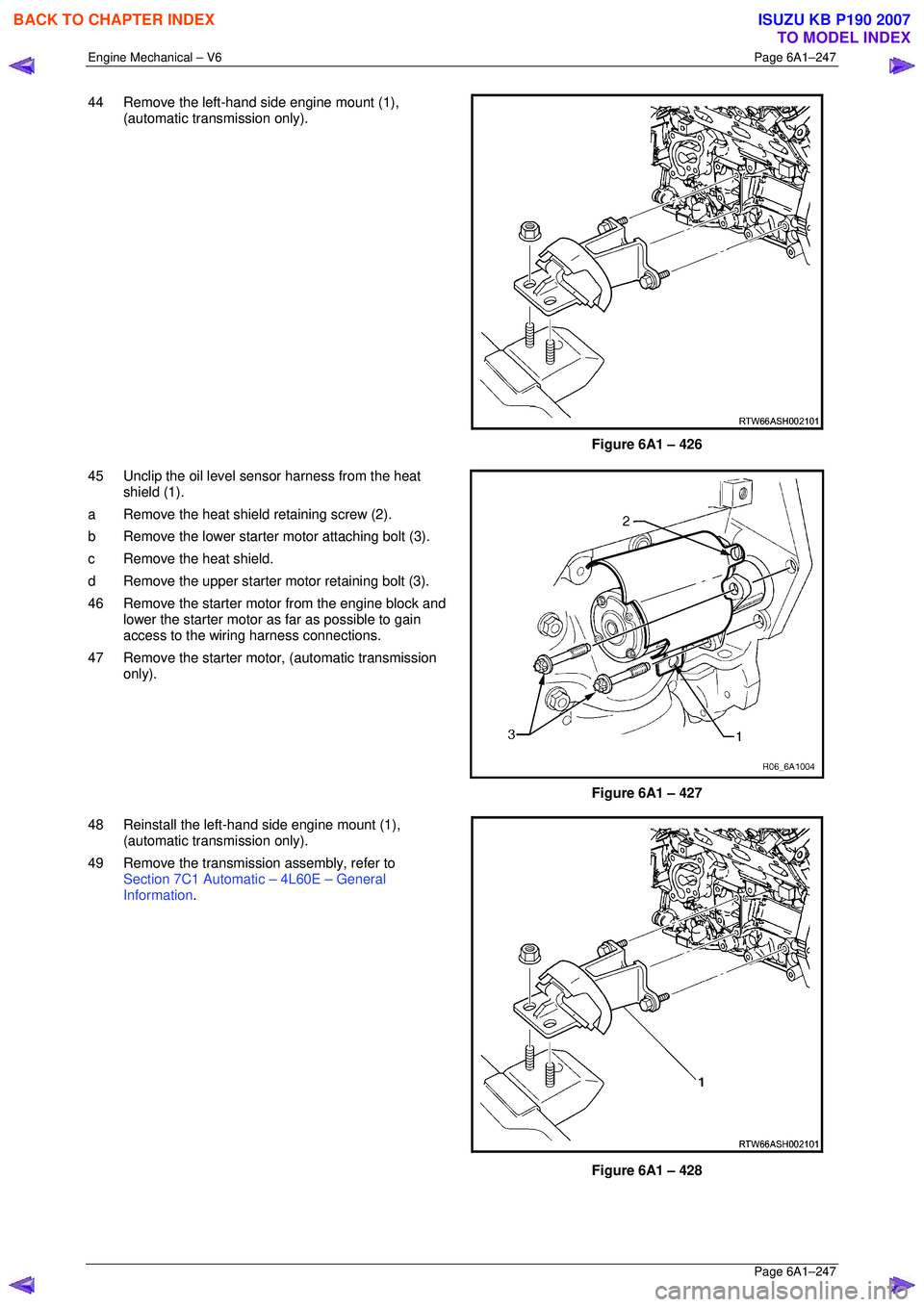
44 Remove the left-hand side engine mount (1),
(automatic transmission only).
Figure 6A1 – 426
45 Unclip the oil level s ensor harness from the heat
shield (1).
a Remove the heat shield retaining screw (2).
b Remove the lower starter motor attaching bolt (3).
c Remove the heat shield.
d Remove the upper starter motor retaining bolt (3).
46 Remove the starter motor from the engine block and lower the starter motor as far as possible to gain
access to the wiring harness connections.
47 Remove the starter moto r, (automatic transmission
only).
Figure 6A1 – 427
48 Reinstall the left-hand side engine mount (1), (automatic transmission only).
49 Remove the transmission assembly, refer to Section 7C1 Automatic – 4L60E – General
Information .
Figure 6A1 – 428
BACK TO CHAPTER INDEX
TO MODEL INDEX
ISUZU KB P190 2007
Page 3027 of 6020

Engine Mechanical – V6 Page 6A1–250
Page 6A1–250
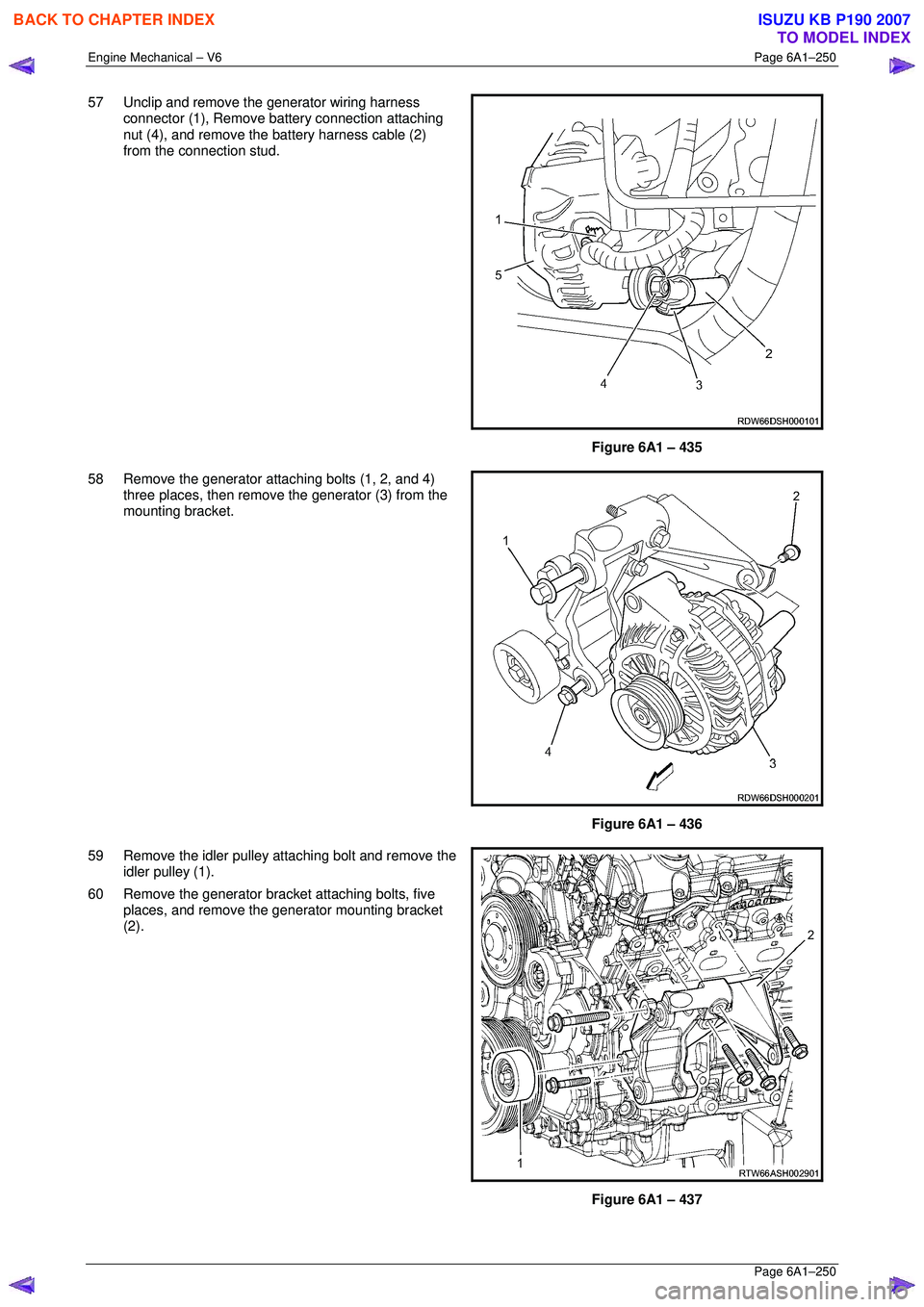
57 Unclip and remove the generator wiring harness
connector (1), Remove ba ttery connection attaching
nut (4), and remove the battery harness cable (2)
from the connection stud.
Figure 6A1 – 435
58 Remove the generator attaching bolts (1, 2, and 4) three places, then remove the generator (3) from the
mounting bracket.
Figure 6A1 – 436
59 Remove the idler pulley attaching bolt and remove the idler pulley (1).
60 Remove the generator bracket attaching bolts, five places, and remove the generator mounting bracket
(2).
Figure 6A1 – 437
BACK TO CHAPTER INDEX
TO MODEL INDEX
ISUZU KB P190 2007
Page 3029 of 6020

Engine Mechanical – V6 Page 6A1–252
Page 6A1–252
65 Remove the engine mount attaching nuts (1), (two
places) on the chassis si de of the left-hand and right-
hand engine mounts.
Figure 6A1 – 441
66 Slowly raise the engine using the engine hoist continue to lift and manoeuvre the engine assembly
clear of the engine compartment.
Figure 6A1 – 442
Disassemble
1 Remove the wiring harness connectors and ground connec tions from the engine and transmission assembly and
carefully set the wiring harness to one side, refer to Section 8A Electrical Body & Chassis.
2 Remove the engine control module (ECM) and mounting bracket, refer to Section 6C1-3 Engine Management – V6
– Service Operations .
3 Mount the engine assembly on a suitable engine stand.
5 Drain the engine oil into a suitable, clean container.
6 Remove the following components: a Oil filter adaptor, refer to 3.3 Oil Filter Adaptor.
b Engine coolant inlet pipe, refer to Section 6B1 Engine Cooling – V6.
c Heater pipe assembly, refer to Section 6B1 Engine Cooling – V6.
d Thermostat assembly, refer to Section 6B1 Engine Cooling – V6.
e Exhaust manifold a ssemblies, refer to 3.11 Exhaust Manifold Assembly .
f Engine coolant outlet pipe, refer to Section 6B1 Engine Cooling – V6.
g Crankshaft position sensor, refer to Section 6C1-3 Engine Management – V6 – Service Operations.
h Knock sensors, refer to Section 6C1-3 Engine Management – V6 – Service Operations.
i Engine mounts and brackets, refer to 3.23 Engine Mounts and Brackets.
j Flexplate assemblies, refer to 4.3 Flexplate Assembly.
BACK TO CHAPTER INDEX
TO MODEL INDEX
ISUZU KB P190 2007