key ISUZU KB P190 2007 Workshop Repair Manual
[x] Cancel search | Manufacturer: ISUZU, Model Year: 2007, Model line: KB P190, Model: ISUZU KB P190 2007Pages: 6020, PDF Size: 70.23 MB
Page 309 of 6020
3B-48 POWER-ASSISTED STEERING SYSTEM
430R300007
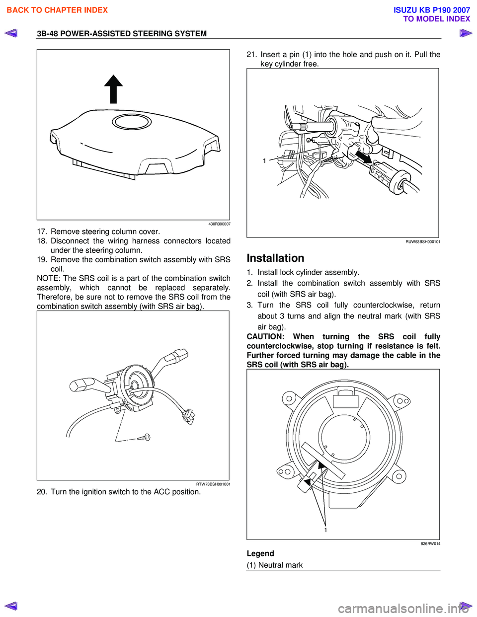
17. Remove steering column cover.
18. Disconnect the wiring harness connectors located under the steering column.
19. Remove the combination switch assembly with SRS coil.
NOTE: The SRS coil is a part of the combination switch
assembly, which cannot be replaced separately.
Therefore, be sure not to remove the SRS coil from the
combination switch assembly (with SRS air bag).
RTW 73BSH001001
20. Turn the ignition switch to the ACC position.
21. Insert a pin (1) into the hole and push on it. Pull the
key cylinder free.
RUW 53BSH000101
Installation
1. Install lock cylinder assembly.
2. Install the combination switch assembly with SRS coil (with SRS air bag).
3. Turn the SRS coil fully counterclockwise, return about 3 turns and align the neutral mark (with SRS
air bag).
CAUTION: When turning the SRS coil fully
counterclockwise, stop turning if resistance is felt.
Further forced turning may damage the cable in the
SRS coil (with SRS air bag).
826RW 014
Legend
(1) Neutral mark
BACK TO CHAPTER INDEX
TO MODEL INDEX
ISUZU KB P190 2007
Page 613 of 6020
5A-20 BRAKE CONTROL SYSTEM
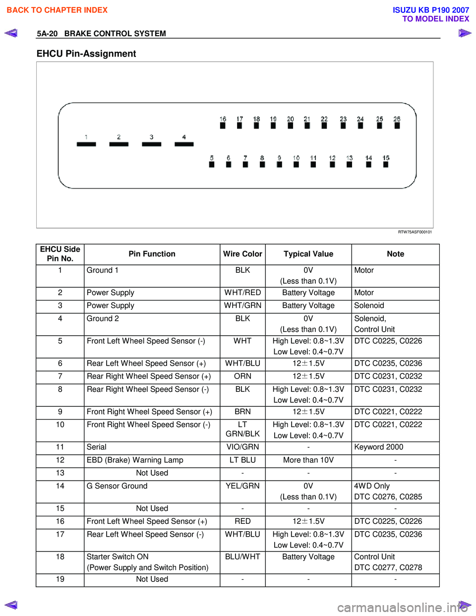
EHCU Pin-Assignment
RTW 75ASF000101
EHCU Side Pin No. Pin Function
Wire Color Typical Value Note
1 Ground 1 BLK 0V
(Less than 0.1V) Motor
2 Power Supply
W HT/RED Battery Voltage Motor
3 Power Supply W HT/GRN Battery Voltage Solenoid
4 Ground 2 BLK 0V
(Less than 0.1V) Solenoid,
Control Unit
5 Front Left W heel Speed Sensor (-) W HT High Level: 0.8~1.3V Low Level: 0.4~0.7V DTC C0225, C0226
6 Rear Left W heel Speed Sensor (+) W HT/BLU 12
±1.5V DTC C0235, C0236
7 Rear Right W heel Speed Sensor (+) ORN 12±1.5V DTC C0231, C0232
8 Rear Right W heel Speed Sensor (-) BLK High Level: 0.8~1.3V
Low Level: 0.4~0.7V DTC C0231, C0232
9 Front Right W heel Speed Sensor (+) BRN
12±1.5V DTC C0221, C0222
10 Front Right W heel Speed Sensor (-) LT
GRN/BLKHigh Level: 0.8~1.3V
Low Level: 0.4~0.7V DTC C0221, C0222
11 Serial
VIO/GRN- Keyword 2000
12 EBD (Brake) W arning Lamp LT BLU More than 10V -
13 Not Used - - -
14 G Sensor Ground YEL/GRN0V
(Less than 0.1V) 4W D Only
DTC C0276, C0285
15 Not Used - - -
16 Front Left W heel Speed Sensor (+) RED 12±1.5V DTC C0225, C0226
17 Rear Left W heel Speed Sensor (-) W HT/BLU High Level: 0.8~1.3V
Low Level: 0.4~0.7V DTC C0235, C0236
18 Starter Switch ON
(Power Supply and Switch Position) BLU/W HT Battery Voltage Control Unit
DTC C0277, C0278
19 Not Used - - -
BACK TO CHAPTER INDEX
TO MODEL INDEX
ISUZU KB P190 2007
Page 622 of 6020
BRAKE CONTROL SYSTEM 5A-29
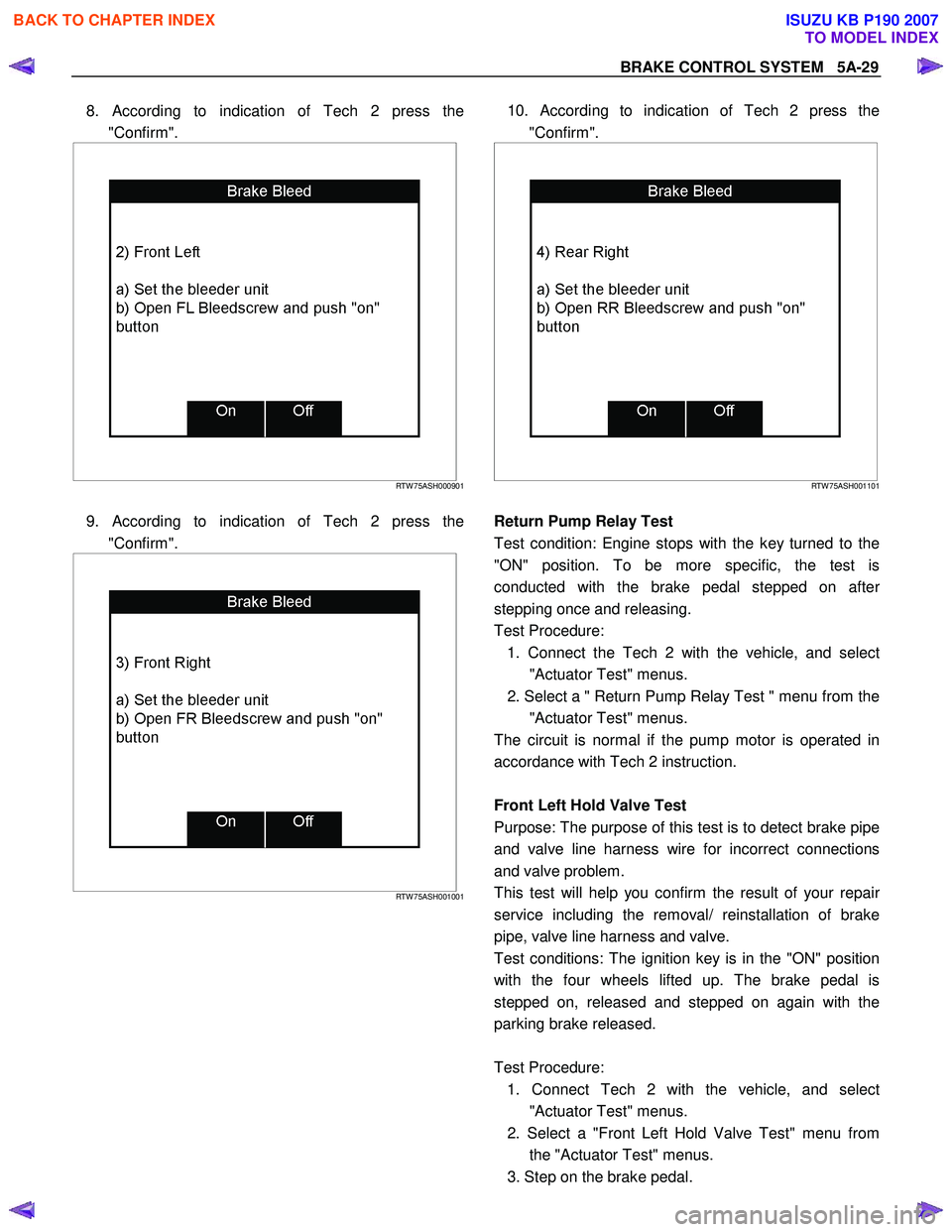
8. According to indication of Tech 2 press the
"Confirm".
RTW 75ASH000901
9. According to indication of Tech 2 press the
"Confirm".
RTW 75ASH001001
10. According to indication of Tech 2 press the
"Confirm".
RTW 75ASH001101
Return Pump Relay Test
Test condition: Engine stops with the key turned to the
"ON" position. To be more specific, the test is
conducted with the brake pedal stepped on afte
r
stepping once and releasing.
Test Procedure: 1. Connect the Tech 2 with the vehicle, and selec
t
"Actuator Test" menus.
2. Select a " Return Pump Relay Test " menu from the "Actuator Test" menus.
The circuit is normal if the pump motor is operated in
accordance with Tech 2 instruction.
Front Left Hold Valve Test
Purpose: The purpose of this test is to detect brake pipe
and valve line harness wire for incorrect connections
and valve problem.
This test will help you confirm the result of your repai
r
service including the removal/ reinstallation of brake
pipe, valve line harness and valve.
Test conditions: The ignition key is in the "ON" position
with the four wheels lifted up. The brake pedal is
stepped on, released and stepped on again with the
parking brake released.
Test Procedure: 1. Connect Tech 2 with the vehicle, and selec
t
"Actuator Test" menus.
2. Select a "Front Left Hold Valve Test" menu from the "Actuator Test" menus.
3. Step on the brake pedal.
BACK TO CHAPTER INDEX
TO MODEL INDEX
ISUZU KB P190 2007
Page 623 of 6020
5A-30 BRAKE CONTROL SYSTEM
4. Release the brake pedal.
5. Make sure that the front left hold solenoid valve "ON" aimed at by Tech 2 and the wheel locked
position are the same.
If different, check brake pipe, valve line harness wiring
and hydraulic unit. Repair is needed if abnormality is
found.
Front Left Release Valve Test
Purpose: The purpose of this test is to detect brake pipe
and valve line harness wire for incorrect connections and
valve problem.
This test will help you confirm the result of your repai
r
service including the removal/ reinstallation of brake
pipe, valve line harness and valve.
Test conditions: The ignition key is in the "ON" position
with the four wheels lifted up. The brake pedal is stepped
on, released and stepped on again with the parking
brake released.
Test Procedure: 1. Connect Tech 2 with the vehicle, and select "Actuator Test" menus.
2. Select a "Front Left Release Valve Test" menu from the "Actuator Test" menus.
3. Step on the brake pedal.
4. Make sure that the front left release solenoid valve "ON" aimed at by Tech 2 and the wheel released
position are the same.
If different, check brake pipe, valve line harness wiring
and hydraulic unit. Repair is needed if abnormality is
found.
Front Right Hold Valve Test
Purpose: The purpose of this test is to detect brake pipe
and valve line harness wire for incorrect connections and
valve problem.
This test will help you confirm the result of your repai
r
service including the removal/ reinstallation of brake
pipe, valve line harness and valve.
Test conditions: The ignition key is in the "ON" position
with the four wheels lifted up. The brake pedal is stepped
on, released and stepped on again with the parking
brake released.
Test Procedure: 1. Connect Tech 2 with the vehicle, and select "Actuator Test" menus.
2. Select a "Front Right Hold Valve Test" menu from the "Actuator Test" menus.
3. Step on the brake pedal.
4. Release the brake pedal.
5. Make sure that the front right hold solenoid valve "ON" aimed at by Tech 2 and the wheel locked
position are the same.
If different, check brake pipe, valve line harness wiring
and hydraulic unit. Repair is needed if abnormality is
found.
Front Right Release Valve Test
Purpose: The purpose of this test is to detect brake pipe
and valve line harness wire for incorrect connections
and valve problem.
This test will help you confirm the result of your repai
r
service including the removal/ reinstallation of brake
pipe, valve line harness and valve.
Test conditions: The ignition key is in the "ON" position
with the four wheels lifted up. The brake pedal is
stepped on, released and stepped on again with the
parking brake released.
Test Procedure: 1. Connect Tech 2 with the vehicle, and selec
t
"Actuator Test" menus.
2. Select a "Front Right Release Valve Test" menu from the "Actuator Test" menus.
3. Step on the brake pedal.
4. Make sure that the front right release solenoid valve "ON" aimed at by Tech 2 and the wheel released
position are the same.
If different, check brake pipe, valve line harness wiring
and hydraulic unit. Repair is needed if abnormality is
found.
Rear Hold Valve Test
Purpose: The purpose of this test is to detect brake pipe
and valve line harness wire for incorrect connections
and valve problem.
This test will help you confirm the result of your repai
r
service including the removal/ reinstallation of brake
pipe, valve line harness and valve.
Test conditions: The ignition key is in the "ON" position
with the four wheels lifted up. The brake pedal is
stepped on, released and stepped on again with the
parking brake released.
Test Procedure: 1. Connect Tech 2 with the vehicle, and selec
t
"Actuator Test" menus.
BACK TO CHAPTER INDEX
TO MODEL INDEX
ISUZU KB P190 2007
Page 624 of 6020
BRAKE CONTROL SYSTEM 5A-31
2. Select a "Rear Hold Valve Test" menu from the
"Actuator Test" menus.
3. Step on the brake pedal.
4. Release the brake pedal.
5. Make sure that the rear hold solenoid valve "ON" aimed at by Tech 2 and the wheel locked position
are the same.
If different, check brake pipe, valve line harness wiring
and hydraulic unit. Repair is needed if abnormality is
found.
Rear Release Valve Test
Purpose: The purpose of this test is to detect brake pipe
and valve line harness wire for incorrect connections and
valve problem.
This test will help you confirm the result of your repai
r
service including the removal/ reinstallation of brake
pipe, valve line harness and valve.
Test conditions: The ignition key is in the "ON" position
with the four wheels lifted up. The brake pedal is stepped
on, released and stepped on again with the parking
brake released.
Test Procedure: 1. Connect Tech 2 with the vehicle, and select "Actuator Test" menus.
2. Select a "Rear Release Valve Test" menu from the "Actuator Test" menus.
3. Step on the brake pedal.
4. Make sure that the rear release solenoid valve "ON" aimed at by Tech 2 and the wheel released position
are the same.
If different, check brake pipe, valve line harness wiring
and hydraulic unit. Repair is needed if abnormality is
found.
BACK TO CHAPTER INDEX
TO MODEL INDEX
ISUZU KB P190 2007
Page 628 of 6020
BRAKE CONTROL SYSTEM 5A-35
Diagnosis By “ABS” Warning Lamp
Illumination Pattern
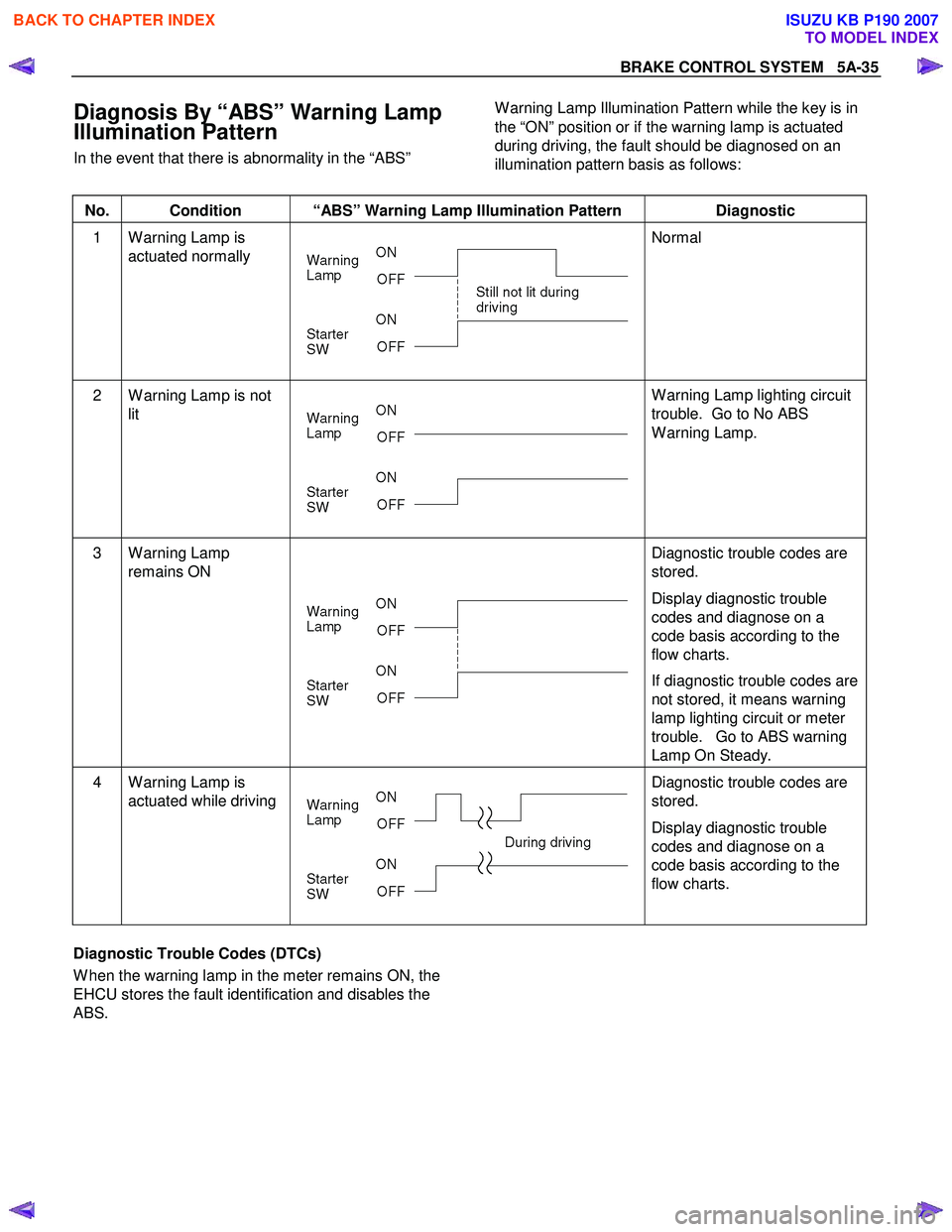
In the event that there is abnormality in the “ABS”
W arning Lamp Illumination Pattern while the key is in
the “ON” position or if the warning lamp is actuated
during driving, the fault should be diagnosed on an
illumination pattern basis as follows:
No. Condition “ABS” Warning Lamp Illumination Pattern Diagnostic
1 W arning Lamp is
actuated normally
Normal
2 W arning Lamp is not
lit
W arning Lamp lighting circuit
trouble. Go to No ABS
W arning Lamp.
3 W arning Lamp remains ON
Diagnostic trouble codes are
stored.
Display diagnostic trouble
codes and diagnose on a
code basis according to the
flow charts.
If diagnostic trouble codes are
not stored, it means warning
lamp lighting circuit or meter
trouble. Go to ABS warning
Lamp On Steady.
4 W arning Lamp is actuated while driving
Diagnostic trouble codes are
stored.
Display diagnostic trouble
codes and diagnose on a
code basis according to the
flow charts.
Diagnostic Trouble Codes (DTCs)
W hen the warning lamp in the meter remains ON, the
EHCU stores the fault identification and disables the
ABS.
BACK TO CHAPTER INDEX
TO MODEL INDEX
ISUZU KB P190 2007
Page 630 of 6020
BRAKE CONTROL SYSTEM 5A-37
4. Notes
• If the following should occur during Diagnostic Trouble Code (DTC) display, the display will be
discontinued. After initial check, the status that
is under the control of ABS will be returned :
– The vehicle starts (The wheels turn) or the
brake pedal is depressed.
• Up to 3 different codes can be stored.
• If the ABS should turn OFF due to an
intermittent defect, the system will be restored
at the next key cycle, if the initial check finds no
abnormality (when IGN is switched from OFF to
ON).
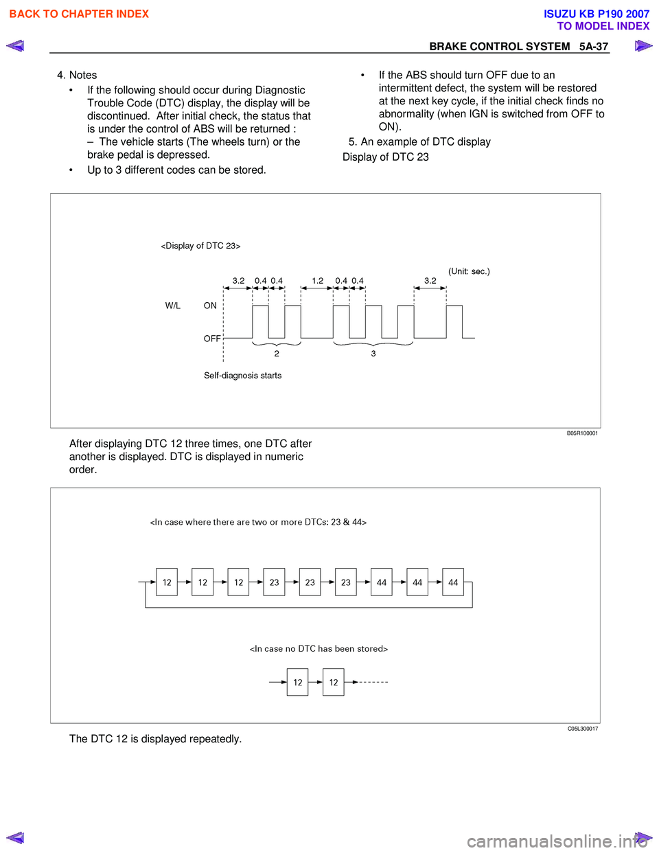
5. An example of DTC display
Display of DTC 23
B05R100001
After displaying DTC 12 three times, one DTC after
another is displayed. DTC is displayed in numeric
order.
C05L300017
The DTC 12 is displayed repeatedly.
BACK TO CHAPTER INDEX
TO MODEL INDEX
ISUZU KB P190 2007
Page 1035 of 6020
Engine Control System (4JH1) 6E-1
SECTION 6E
ENGINE CONTROL SYSTEM (4JH1)
TABLE OF CONTENTS
Specifications ..................................................... 6E-4
Schematic And Routing Diagrams ..................... 6E-5 Vacuum Hose Routing Diagram...................... 6E-5
Engine Controls Schematics ........................... 6E-7
Component Locator ............................................ 6E-18 Engine Controls Component Views ................ 6E-18
Engine Control Module (ECM) Connector
End Views ...................................................... 6E-22
Engine Control Connector End Views ............. 6E-25
Diagnostic Information And Prosedures............. 6E-30 Engine Control System Check Sheet .............. 6E-30
Diagnostic Starting Point - Engine Controls .... 6E-31
Breaker Box .................................................... 6E-32
Diagnostic System Check - Engine Controls .. 6E-33
Scan Tool Data List ......................................... 6E-36
Scan Tool Data Definitions.............................. 6E-37
Scan Tool Output Controls .............................. 6E-40
Scan Tool Does Not Power Up ....................... 6E-41
Scan Tool Does Not Communicate with Keyword
2000 Device ................................................... 6E-42
Lost Communication with The Engine Control
Module (ECM) ............................................... 6E-44
Engine Cranks but Does Not Run ................... 6E-47
Diagnostic Trouble Code (DTC) List ............... 6E-50
DTC P0100 (Symptom Code 7)
(Flash Code 65) ............................................. 6E-66
DTC P0100 (Symptom Code 9)
(Flash Code 65) ............................................ 6E-68
DTC P0100 (Symptom Code B)
(Flash Code 65) ............................................ 6E-70
DTC P0100 (Symptom Code C)
(Flash Code 65) ............................................ 6E-73
DTC P0105 (Symptom Code 1)
(Flash Code 34) ............................................ 6E-75
DTC P0105 (Symptom Code 2)
(Flash Code 34) ............................................ 6E-78
DTC P0105 (Symptom Code 7)
(Flash Code 34) ............................................ 6E-81
DTC P0105 (Symptom Code 9)
(Flash Code 34) ............................................ 6E-83
DTC P0110 (Symptom Code 1)
(Flash Code 23) ............................................ 6E-85
DTC P0110 (Symptom Code 2)
(Flash Code 23) ............................................ 6E-88
DTC P0115 (Symptom Code 1)
(Flash Code 14) ............................................ 6E-90
DTC P0115 (Symptom Code 2)
(Flash Code 14) ............................................ 6E-93
DTC P0180 (Symptom Code B)
(Flash Code 15) ............................................ 6E-95
DTC P0215 (Symptom Code A)
(Flash Code 52............................................... 6E-96
DTC P0215 (Symptom Code B)
(Flash Code 52) ............................................ 6E-98
DTC P0215 (Symptom Code C)
(Flash Code 52) ............................................ 6E-100
DTC P0215 (Symptom Code D)
(Flash Code 52) ............................................ 6E-102
DTC P0216 (Symptom Code A,B)
(Flash Code 54) ............................................ 6E-103
DTC P0243 (Symptom Code 3)
(Flash Code 64) ............................................ 6E-107
DTC P0243 (Symptom Code 4)
(Flash Code 64) ............................................ 6E-111
DTC P0243 (Symptom Code 5)
(Flash Code 64) ............................................. 6E-114
DTC P0243 (Symptom Code 6)
(Flash Code 64) ............................................. 6E-118
DTC P0243 (Symptom Code 8)
(Flash Code 65) ............................................. 6E-121
DTC P0251 (Symptom Code 6)
(Flash Code 53) ............................................ 6E-123
DTC P0251 (Symptom Code 7)
(Flash Code 53) ............................................ 6E-125
DTC P0251 (Symptom Code 9, A, B, C)
(Flash Code 53) ............................................ 6E-127
DTC P0251 (Symptom Code E)
(Flash Code 53) ............................................ 6E-129
DTC P0335 (Symptom Code B, D)
(Flash Code 43) ............................................ 6E-130
DTC P0335 (Symptom Code E)
(Flash Code 43) ............................................. 6E-134
DTC P0380 (Symptom Code 4)
(Flash Code 66) ............................................ 6E-136
BACK TO CHAPTER INDEX
TO MODEL INDEX
ISUZU KB P190 2007
Page 1056 of 6020
6E-22 Engine Control System (4JH1)
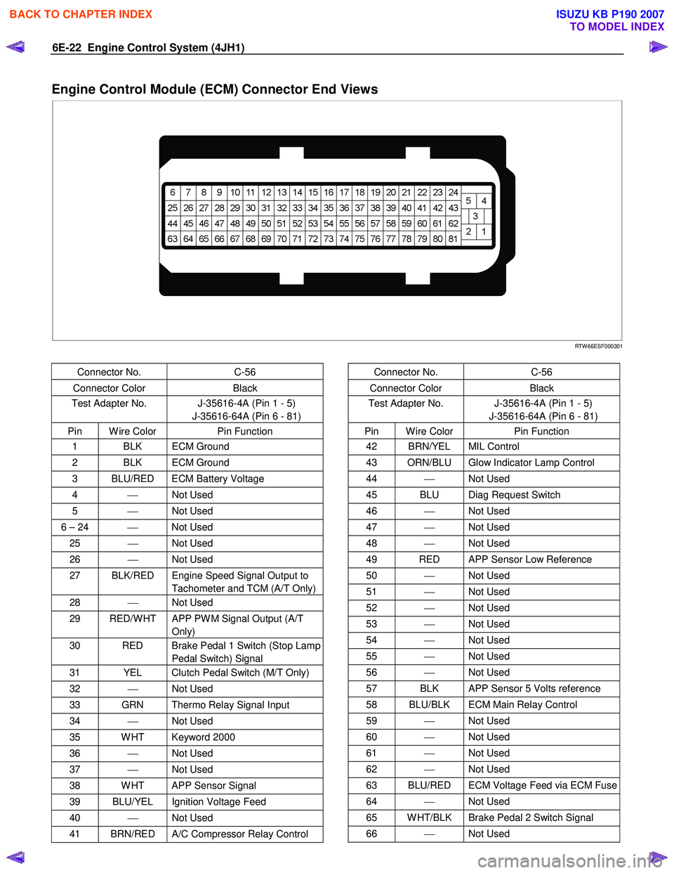
Engine Control Module (ECM) Connector End Views
RTW 66ESF000301
Connector No. C-56
Connector Color Black
Test Adapter No. J-35616-4A (Pin 1 - 5)
J-35616-64A (Pin 6 - 81)
Pin W ire Color Pin Function
1 BLK ECM Ground
2 BLK ECM Ground
3 BLU/RED ECM Battery Voltage
4 Not Used
5 Not Used
6 – 24 Not Used
25 Not Used
26 Not Used
27 BLK/RED Engine Speed Signal Output to
Tachometer and TCM (A/T Only)
28 Not Used
29 RED/W HT APP PW M Signal Output (A/T
Only)
30 RED Brake Pedal 1 Switch (Stop Lamp Pedal Switch) Signal
31 YEL Clutch Pedal Switch (M/T Only)
32 Not Used
33 GRN Thermo Relay Signal Input
34 Not Used
35 W HT Keyword 2000
36 Not Used
37 Not Used
38 W HT APP Sensor Signal
39 BLU/YEL Ignition Voltage Feed
40 Not Used
41 BRN/RED A/C Compressor Relay Control
Connector No. C-56
Connector Color Black
Test Adapter No. J-35616-4A (Pin 1 - 5)
J-35616-64A (Pin 6 - 81)
Pin W ire Color Pin Function
42 BRN/YEL MIL Control
43 ORN/BLU Glow Indicator Lamp Control
44 Not Used
45 BLU Diag Request Switch
46 Not Used
47 Not Used
48 Not Used
49 RED APP Sensor Low Reference
50 Not Used
51 Not Used
52 Not Used
53 Not Used
54 Not Used
55 Not Used
56 Not Used
57 BLK APP Sensor 5 Volts reference
58 BLU/BLK ECM Main Relay Control
59 Not Used
60 Not Used
61 Not Used
62 Not Used
63 BLU/RED ECM Voltage Feed via ECM Fuse
64 Not Used
65 W HT/BLK Brake Pedal 2 Switch Signal
66 Not Used
BACK TO CHAPTER INDEX
TO MODEL INDEX
ISUZU KB P190 2007
Page 1060 of 6020
6E-26 Engine Control System (4JH1)
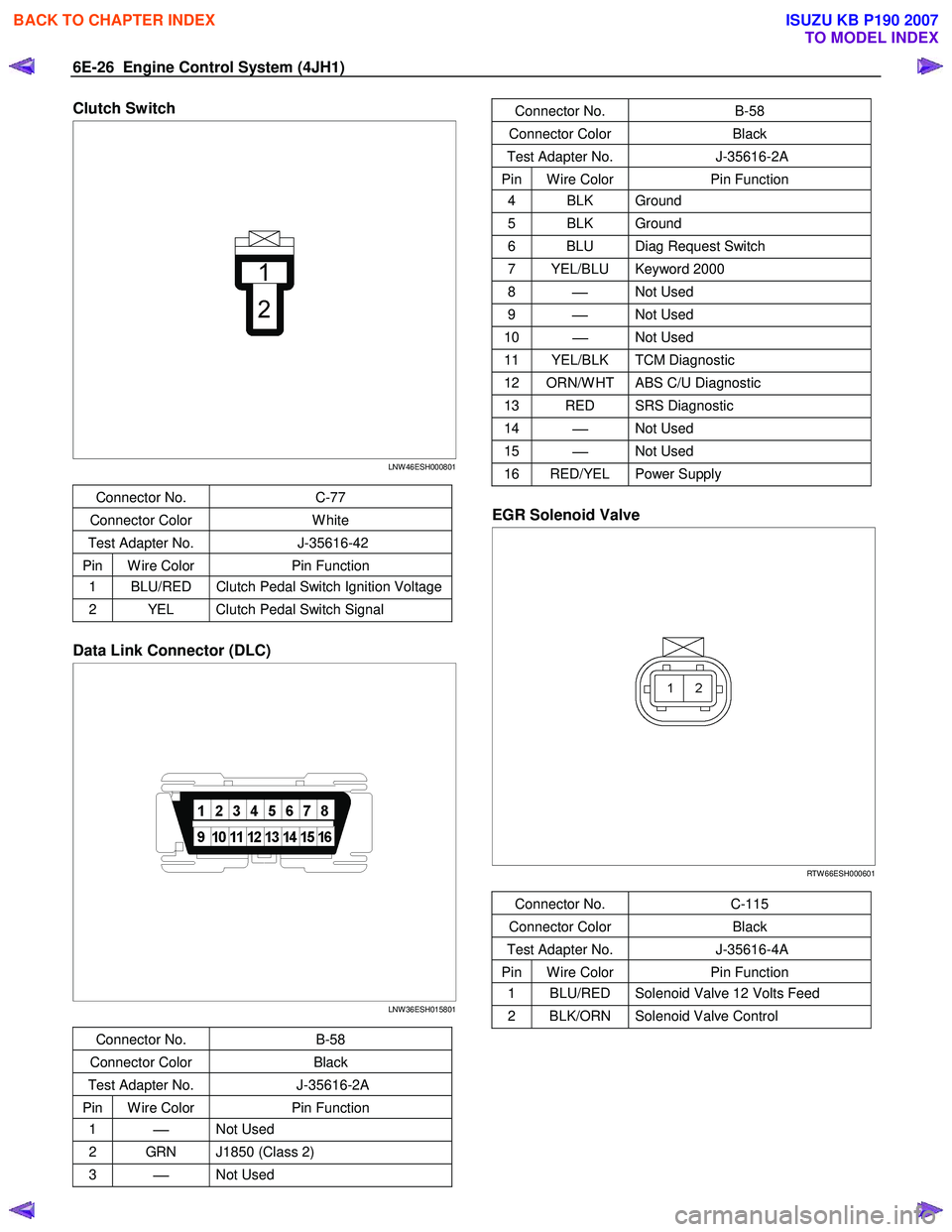
Clutch Switch
LNW 46ESH000801
Connector No. C-77
Connector Color W hite
Test Adapter No. J-35616-42
Pin W ire Color Pin Function
1 BLU/RED Clutch Pedal Switch Ignition Voltage
2 YEL Clutch Pedal Switch Signal
Data Link Connector (DLC)
LNW 36ESH015801
Connector No. B-58
Connector Color Black
Test Adapter No. J-35616-2A
Pin W ire Color Pin Function
1
Not Used
2 GRN J1850 (Class 2)
3
Not Used
Connector No. B-58
Connector Color Black
Test Adapter No. J-35616-2A
Pin W ire Color Pin Function
4 BLK Ground
5 BLK Ground
6 BLU Diag Request Switch
7 YEL/BLU Keyword 2000
8
Not Used
9
Not Used
10
Not Used
11 YEL/BLK TCM Diagnostic
12 ORN/W HT ABS C/U Diagnostic
13 RED SRS Diagnostic
14
Not Used
15
Not Used
16 RED/YEL Power Supply
EGR Solenoid Valve
RTW 66ESH000601
Connector No. C-115
Connector Color Black
Test Adapter No. J-35616-4A
Pin W ire Color Pin Function
1 BLU/RED Solenoid Valve 12 Volts Feed
2 BLK/ORN Solenoid Valve Control
BACK TO CHAPTER INDEX
TO MODEL INDEX
ISUZU KB P190 2007