bulb ISUZU TF SERIES 2004 Workshop Manual
[x] Cancel search | Manufacturer: ISUZU, Model Year: 2004, Model line: TF SERIES, Model: ISUZU TF SERIES 2004Pages: 4264, PDF Size: 72.63 MB
Page 30 of 4264

9A-10 SUPPLEMENTAL RESTRAINT SYSTEM
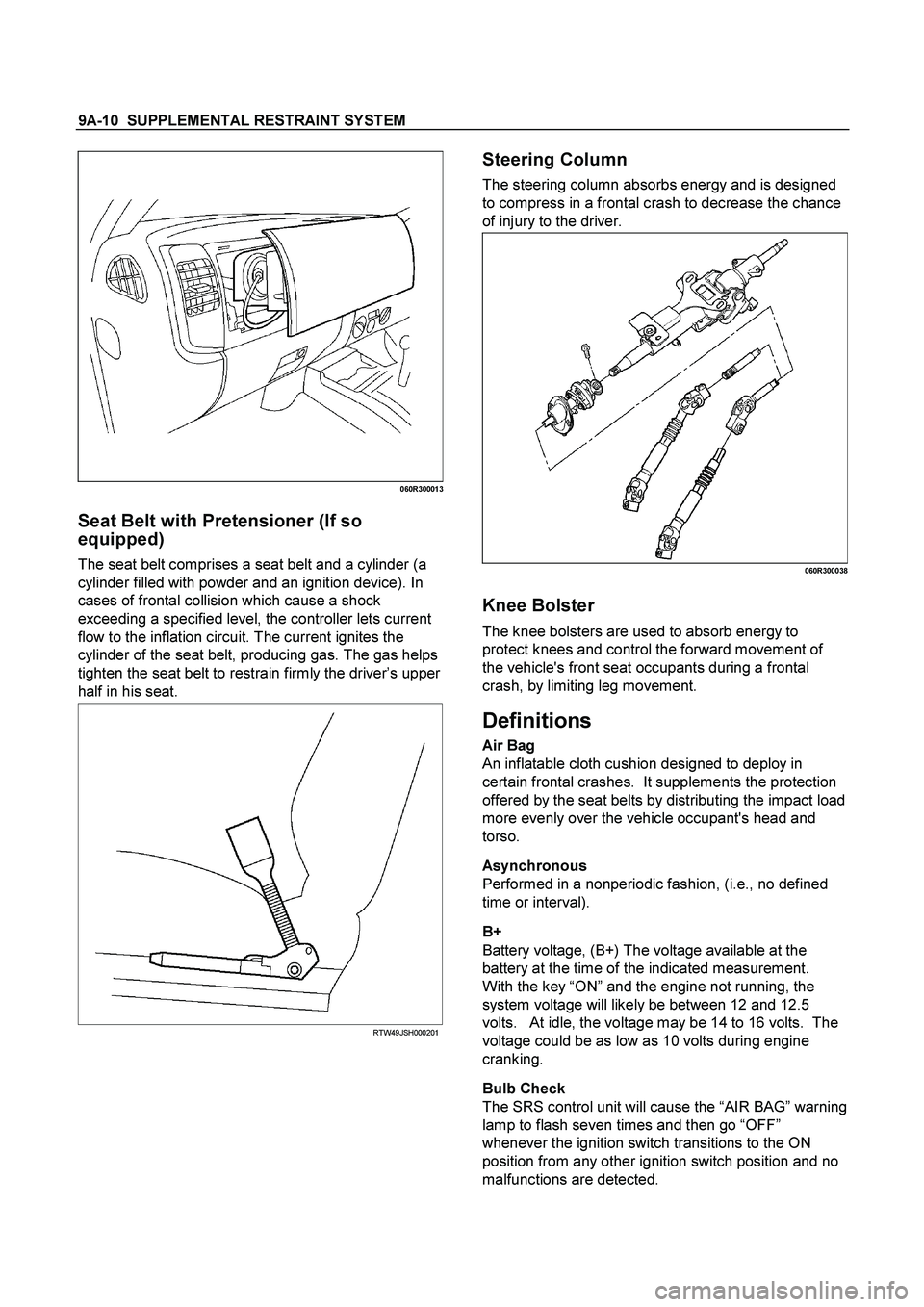
060R300013
Seat Belt with Pretensioner (If so
equipped)
The seat belt comprises a seat belt and a cylinder (a
cylinder filled with powder and an ignition device). In
cases of frontal collision which cause a shock
exceeding a specified level, the controller lets current
flow to the inflation circuit. The current ignites the
cylinder of the seat belt, producing gas. The gas helps
tighten the seat belt to restrain firmly the driver’s upper
half in his seat.
RTW49JSH000201
Steering Column
The steering column absorbs energy and is designed
to compress in a frontal crash to decrease the chance
of injury to the driver.
060R300038
Knee Bolster
The knee bolsters are used to absorb energy to
protect knees and control the forward movement of
the vehicle's front seat occupants during a frontal
crash, by limiting leg movement.
Definitions
Air Bag
An inflatable cloth cushion designed to deploy in
certain frontal crashes. It supplements the protection
offered by the seat belts by distributing the impact load
more evenly over the vehicle occupant's head and
torso.
Asynchronous
Performed in a nonperiodic fashion, (i.e., no defined
time or interval).
B+
Battery voltage, (B+) The voltage available at the
battery at the time of the indicated measurement.
With the key “ON” and the engine not running, the
system voltage will likely be between 12 and 12.5
volts. At idle, the voltage may be 14 to 16 volts. The
voltage could be as low as 10 volts during engine
cranking.
Bulb Check
The SRS control unit will cause the “AIR BAG” warning
lamp to flash seven times and then go “OFF”
whenever the ignition switch transitions to the ON
position from any other ignition switch position and no
malfunctions are detected.
Page 85 of 4264

RESTRAINT CONTROL 9A1-15
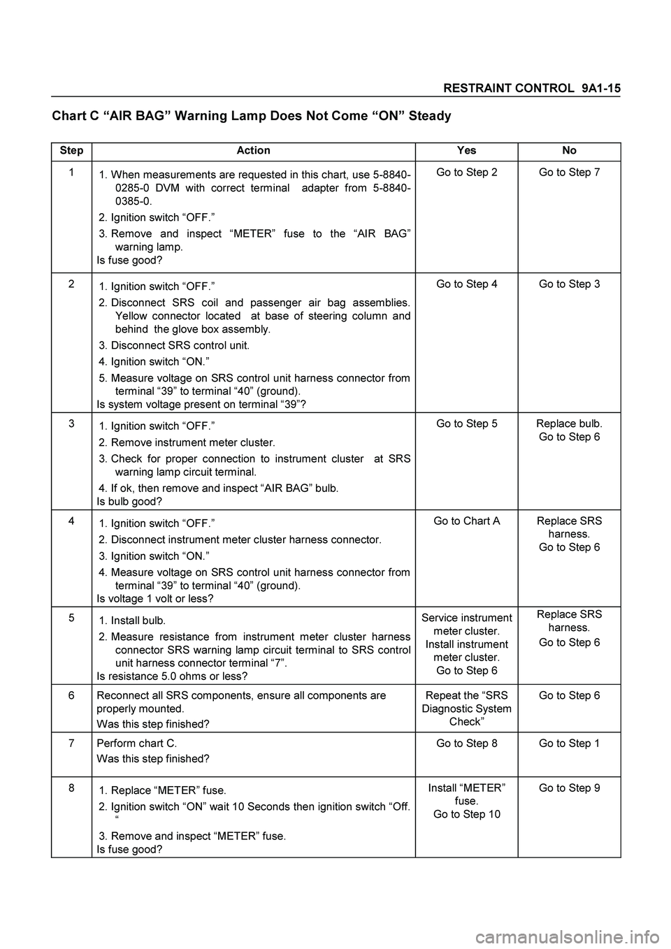
Chart C “AIR BAG” Warning Lamp Does Not Come “ON” Steady
Step Action Yes No
1
1. When measurements are requested in this chart, use 5-8840-
0285-0 DVM with correct terminal adapter from 5-8840-
0385-0.
2. Ignition switch “OFF.”
3. Remove and inspect “METER” fuse to the “AIR BAG”
warning lamp.
Is fuse good? Go to Step 2 Go to Step 7
2
1. Ignition switch “OFF.”
2. Disconnect SRS coil and passenger air bag assemblies.
Yellow connector located at base of steering column and
behind the glove box assembly.
3. Disconnect SRS control unit.
4. Ignition switch “ON.”
5. Measure voltage on SRS control unit harness connector from
terminal “39” to terminal “40” (ground).
Is system voltage present on terminal “39”? Go to Step 4 Go to Step 3
3
1. Ignition switch “OFF.”
2. Remove instrument meter cluster.
3. Check for proper connection to instrument cluster at SRS
warning lamp circuit terminal.
4. If ok, then remove and inspect “AIR BAG” bulb.
Is bulb good? Go to Step 5 Replace bulb.
Go to Step 6
4
1. Ignition switch “OFF.”
2. Disconnect instrument meter cluster harness connector.
3. Ignition switch “ON.”
4. Measure voltage on SRS control unit harness connector from
terminal “39” to terminal “40” (ground).
Is voltage 1 volt or less? Go to Chart A Replace SRS
harness.
Go to Step 6
5
1. Install bulb.
2. Measure resistance from instrument meter cluster harness
connector SRS warning lamp circuit terminal to SRS control
unit harness connector terminal “7”.
Is resistance 5.0 ohms or less? Service instrument
meter cluster.
Install instrument
meter cluster.
Go to Step 6 Replace SRS
harness.
Go to Step 6
6 Reconnect all SRS components, ensure all components are
properly mounted.
Was this step finished? Repeat the “SRS
Diagnostic System
Check” Go to Step 6
7 Perform chart C.
Was this step finished? Go to Step 8 Go to Step 1
8
1. Replace “METER” fuse.
2. Ignition switch “ON” wait 10 Seconds then ignition switch “Off.
“
3. Remove and inspect “METER” fuse.
Is fuse good? Install “METER”
fuse.
Go to Step 10 Go to Step 9
Page 88 of 4264

9A1-18 RESTRAINT CONTROL SYSTEM
DTC Will Clear When
The ignition switch is turned “OFF.”
DTC Chart Test Description
Number(s) below refer to step number(s) on the
diagnostic chart:
2.
This test determines whether the malfunction is in
the SRS control unit.
3.
This test verifies connection of the yellow connector.
4.
This test cheeks for proper operation of the shorting
clip in the yellow connector.
5.
The test checks for a malfunction passenger air bag
assembly.
6.
This test determines whether the malfunctioning is
due to shortening in the wiring.
Diagnostic Aids
An intermittent condition is likely to be caused by a short
between circuits “Passenger Bag High” and “Passenger
Bag Low” or a malfunctioning shorting clip on the
passenger air bag assembly which would require
replacement of the air bag assembly. The test for this
diagnostic trouble code is only run while “AIR BAG”
warning lamp is performing the bulb check. When a
scan tool “Clear Codes” command is issued and the
malfunction is still present, the DTC will not reappear
until the next ignition cycle.
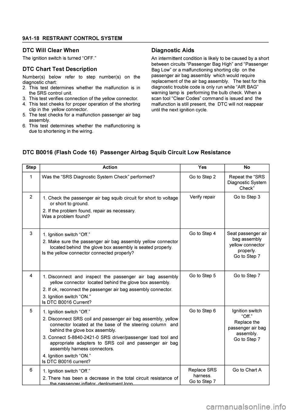
DTC B0016 (Flash Code 16) Passenger Airbag Squib Circuit Low Resistance
Step Action Yes No
1 Was the “SRS Diagnostic System Check” performed? Go to Step 2 Repeat the “SRS
Diagnostic System
Check”
2
1. Check the passenger air bag squib circuit for short to voltage
or short to ground.
2. If the problem found, repair as necessary.
Was a problem found? Verify repair Go to Step 3
3
1. Ignition switch “Off.”
2. Make sure the passenger air bag assembly yellow connector
located behind the glove box assembly is seated properly.
Is the yellow connector connected properly? Go to Step 4 Seat passenger air
bag assembly
yellow connector
properly.
Go to Step 7
4
1. Disconnect and inspect the passenger air bag assembly
yellow connector located behind the glove box assembly.
2. If ok, reconnect the passenger air bag assembly connector.
3. Ignition switch “ON.”
Is DTC B0016 Current? Go to Step 5 Go to Step 7
5
1. Ignition switch “Off.”
2. Disconnect SRS coil and passenger air bag assembly, yellow
connector located at the base of the steering column and
behind the glove box assembly.
3. Connect 5-8840-2421-0 SRS driver/passenger load tool and
appropriate adapters to SRS coil and passenger air bag
assembly harness connectors.
4. Ignition switch “ON.”
Is DTC B0016 current? Go to Step 6 Ignition switch
“Off.”
Replace the
passenger air bag
assembly.
Go to Step 7
6
1. Ignition switch “Off.”
2. There has been a decrease in the total circuit resistance of
the passenger inflator deployment loop
Replace SRS
harness.
Go to Step 7 Go to Chart A
Page 91 of 4264

RESTRAINT CONTROL 9A1-21
DTC Will Clear When
The ignition switch is turned “OFF.”
DTC Chart Test Description
Number(s) below refer to step number(s) on the
diagnostic chart:
2.
This test determines whether the malfunction is in
the SRS control unit.
3.
This test verifies proper connection of the yellow
connector.
4.
This test checks for proper contact and/or corrosion
of the yellow connector terminals.
5.
The test checks for a malfunctioning passenger ai
r
bag assembly.
6.
This test determines whether the malfunction is due
to high resistance in the wiring.
Diagnostic Aids
An intermittent condition is likely to be caused by a poor
connection at the passenger air bag assembly harness
connector terminals “1” and “2”, SRS control unit
terminal “48” and “47”, or a poor wire to terminal
connection in circuits “Passenger Bag High” and
“Passenger Bag Low”. This test for this diagnostic
trouble code is only run while the “AIR BAG” warning
lamp is performing the bulb check. When a scan tool
“Clear Codes” command is issued and the malfunction
is still present, the DTC will not reappear until the next
ignition cycle.
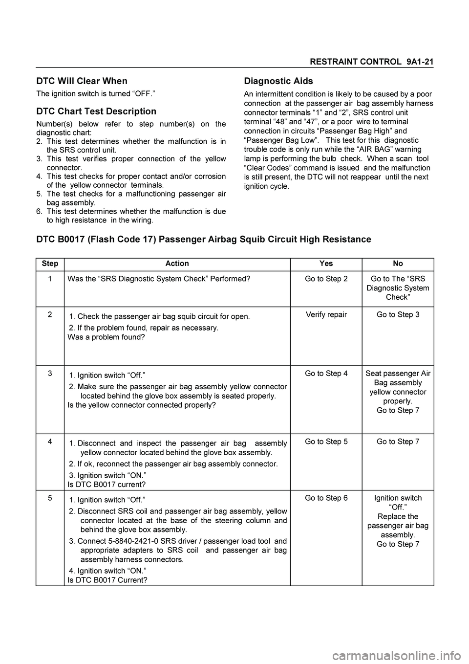
DTC B0017 (Flash Code 17) Passenger Airbag Squib Circuit High Resistance
Step Action Yes No
1 Was the “SRS Diagnostic System Check” Performed? Go to Step 2 Go to The “SRS
Diagnostic System
Check”
2
1. Check the passenger air bag squib circuit for open.
2. If the problem found, repair as necessary.
Was a problem found? Verify repair Go to Step 3
3
1. Ignition switch “Off.”
2. Make sure the passenger air bag assembly yellow connector
located behind the glove box assembly is seated properly.
Is the yellow connector connected properly? Go to Step 4 Seat passenger Air
Bag assembly
yellow connector
properly.
Go to Step 7
4
1. Disconnect and inspect the passenger air bag assembly
yellow connector located behind the glove box assembly.
2. If ok, reconnect the passenger air bag assembly connector.
3. Ignition switch “ON.”
Is DTC B0017 current? Go to Step 5 Go to Step 7
5
1. Ignition switch “Off.”
2. Disconnect SRS coil and passenger air bag assembly, yellow
connector located at the base of the steering column and
behind the glove box assembly.
3. Connect 5-8840-2421-0 SRS driver / passenger load tool and
appropriate adapters to SRS coil and passenger air bag
assembly harness connectors.
4. Ignition switch “ON.”
Is DTC B0017 Current? Go to Step 6 Ignition switch
“Off.”
Replace the
passenger air bag
assembly.
Go to Step 7
Page 97 of 4264

RESTRAINT CONTROL 9A1-27
DTC Will Set When
The combined resistance of the driver air bag
assembly, SRS Coil assembly, harness wiring circuits
“Driver Bag High” and “Driver Bag Low”, and connector
terminal contact is above a specified value. This test is
run once each ignition cycle during the “Resistance
Measurement Test” when:
1.
No “higher priority faults” are detected during “Turn–
ON”
2.
“Ignition 1” voltage is in the specified value.
Action Taken
SRS control unit turns “ON” the “AIR BAG” warning
lamp and sets DTC B0022.
DTC Will Clear When
The ignition switch is turned “OFF.”
DTC Chart Test Description
Number(s) below refer to circled number(s) on the
diagnostic chart:
2.
This test determines whether the malfunction is in
the SRS control unit.
3.
This test verifies proper connection of the yellow
connector at the base of the steering column.
4.
This test checks for proper operation of the shorting
clip in the yellow connector.
5.
This test isolate the malfunction to one side of the
SRS coil assembly yellow connector located at the
base of steering column.
6.
This test determines whether the malfunction is due
to shortening in the wiring.
7.
This test determines whether the malfunction is in
the SRS coil assembly or the driver air bag
assembly.
Diagnostic Aids
An intermittent condition is likely to be caused by a short
between circuit “Driver Bag High” or “Driver Bag Low”
or a malfunctioning shorting clip on the driver air bag
assembly or SRS coil assembly which would require
replacement of the component. The test for this
diagnostic trouble code is only run while the “AIR BAG”
warning lamp is performing the bulb check. When a
scan tool “Clear Codes” command is issued and the
malfunction is still present, the DTC will not reappear
until the next ignition cycle.
DTC B0022 (Flash Code 22) Driver Airbag Squib Circuit Low Resistance
Step Action Yes No
1 Perform the “SRS Diagnostic System Check.”
Was the “SRS Diagnostic System Check” performed? Go to Step 2 Go to the “SRS
Diagnostic System
Check”
2
1. Check the driver air bag squib circuit for short to voltage or
short to ground.
2. If the problem found, repair as necessary.
Was a problem found? Verify repair Go to Step 3
3
1. Ignition switch “OFF.”
2. Make sure the SRS coil assembly yellow connector located
at the base of steering column is seated properly.
Is the connector connected properly? Go to Step 4 Seat driver air bag
assembly
connector
properly.
Go to Step 8
4
1. Disconnect and inspect the SRS coil assembly yellow
connector located base of steering column.
2. If ok, reconnect the SRS coil assembly yellow connector.
3. Ignition switch “ON.”
Is DTC B0022 current? Go to Step 5 Go to Step 8
Page 103 of 4264

RESTRAINT CONTROL 9A1-33
DTC Will Set When
The combined resistance of the driver air bag
assembly, SRS Coil assembly, harness wiring circuits
“Driver Bag High” and “Driver Bag Low”, and connector
terminal contact is above a specified value. This test
run once each ignition cycle during the “Resistance
Measurement Test” when:
1.
No “higher priority faults” are detected during “Turn–
ON”
2.
“Ignition 1” voltage is in the specified value.
Action Taken
SRS control unit turns “ON” the “AIR BAG” warning
lamp and sets DTC B0026.
DTC Will Clear When
The ignition switch is turned “OFF”.
DTC Chart Test Description
Number(s) below refer to step number(s) on the
diagnostic chart:
2.
This test determines whether the malfunction is in
the SRS control unit.
3.
This test verifies proper connection of the yellow
connector at the base of the steering column.
4.
This test checks for proper contact and/or corrosion
of the connector terminals at the base of steering
column.
5.
This test isolate the malfunction to one side of the
SRS coil assembly yellow connector located at the
base of the steering column.
6.
This test determines whether the malfunction is due
to high resistance in the wiring.
7.
This test determines whether the malfunction is in
the SRS coil assembly or the driver air bag
assembly.
Diagnostic Aids
An intermittent condition is likely to be caused by a poor
connection at terminals “1” and “2” of the SRS coil
connector at the base of the steering column, terminal
“1” and “2” of the driver air bag assembly connector at
the top of the steering column, SRS control unit
terminals “45” and “46” or a poor wire to terminal
connection in circuit “Driver Bag High” or “Driver Bag
Low” The test for this diagnostic trouble code is onl
y
run while the “AIR BAG” warning lamp is performing
the bulb check. When a scan tool “Clear Codes”
command is issued and the malfunction is still present,
the DTC will not reappear until the next ignition cycle.
DTC B0026 (Flash Code 26) Driver Airbag Squib Circuit High Resistance
Step Action Yes No
1 Perform the “SRS Diagnostic System Check”.
Was the “SRS Diagnostic System Check” performed? Go to Step 2 Repeat the “SRS
Diagnostic System
Check”
2
1. Check the driver air bag squib circuit for open.
2. If the problem found, repair as necessary.
Was a problem found? Verify repair Go to Step 3
3
1. Ignition switch “OFF.”
2. Disconnect SRS coil assembly yellow connector located at
base of steering column is seated properly.
Is the connector connected properly? Go to Step 4 Seat SRS coil
assembly
connector
properly.
Go to Step 8
Page 112 of 4264

9A1-42 RESTRAINT CONTROL SYSTEM
DTC Will Set When
The combined resistance of the passenger pretensioner
assembly, harness wiring circuits “Passsenger
Pretensioner High” and “Passenger Pretensioner Low”,
and connector terminal contact is above a specified
value. This test is run once each ignition cycle during
the “Resistance Measurement Test” when:
1.
No “higher priority faults” are detected during “Turn–
ON”,
2.
“Ignition 1” voltage is in the specified value.
Action Taken
SRS control unit turns “ON” the “AIR BAG” warning
lamp and sets a diagnostic trouble code.
DTC Will Clear When
The ignition switch is turned “OFF.”
DTC Chart Test Description
Number(s) below refer to step number(s) on the
diagnostic chart:
2.
This test determines whether the malfunction is in
the SRS control unit.
3.
This test verifies connection of the yellow connector.
4.
This test cheeks for proper operation of the shorting
clip in the yellow connector.
5.
The test checks for a malfunction passenge
r
pretensioner assembly.
6.
This test determines whether the malfunctioning is
due to shortening in the wiring.
Diagnostic Aids
An intermittent condition is likely to be caused by a short
between circuits “Passenger Pretensioner High” and
“Passenger Pretensioner Low” or a malfunctioning
shorting clip on the passenger pretensioner assembly
which would require replacement of the pretensioner
assembly. The test for this diagnostic trouble code is
only run while “AIR BAG” warning lamp is performing
the bulb check. When a scan tool “Clear Codes”
command is issued and the malfunction is still present,
the DTC will not reappear until the next ignition cycle.
Page 115 of 4264

RESTRAINT CONTROL 9A1-45
DTC Will Set When
The combined resistance of the passenger air
pretensioner assembly, harness wiring circuits
“Passenger Pretensioner High” and “Passenger
Pretensioner Low”, and connector terminal contact is
above a specified value. This test is run once each
ignition cycle during the “Resistance Measurement
Test” when:
1.
No “higher priority faults” are detected during “Turn–
ON”,
2.
“Ignition 1” voltage is in the specified value.
Action Taken
SRS control unit turns “ON” the “AIR BAG” warning
lamp and sets a diagnostic trouble code.
DTC Will Clear When
The ignition switch is turned “OFF.”
DTC Chart Test Description
Number(s) below refer to step number(s) on the
diagnostic chart:
2.
This test determines whether the malfunction is in
the SRS control unit.
3.
This test verifies proper connection of the yellow
connector.
4.
This test checks for proper contact and/or corrosion
of the yellow connector terminals.
5.
The test checks for a malfunctioning passenge
r
pretensioner assembly.
6.
This test determines whether the malfunction is due
to high resistance in the wiring.
Diagnostic Aids
An intermittent condition is likely to be caused by a poor
connection at the passenger pretensioner assembly
harness connector terminals “1” and “2”, SRS control
unit terminal “44” and “43”, or a poor wire to terminal
connection in circuits “Passenger Pretensioner High”
and “Passenger Pretensioner Low”. This test for this
diagnostic trouble code is only run while the “AIR BAG”
warning lamp is performing the bulb check. When a
scan tool “Clear Codes” command is issued and the
malfunction is still present, the DTC will not reappear
until the next ignition cycle.
Page 121 of 4264

RESTRAINT CONTROL 9A1-51
DTC Will Set When
The combined resistance of the driver pretensioner
assembly, harness wiring circuits “Driver Pretensioner
High” and “Driver Pretensioner Low”, and connector
terminal contact is above a specified value. This test is
run once each ignition cycle during the “Resistance
Measurement Test” when:
1.
No “higher priority faults” are detected during “Turn–
ON”
2.
“Ignition 1” voltage is in the specified value.
Action Taken
SRS control unit turns “ON” the “AIR BAG” warning
lamp and sets DTC B0064.
DTC Will Clear When
The ignition switch is turned “OFF.”
DTC Chart Test Description
Number(s) below refer to circled number(s) on the
diagnostic chart:
2.
This test determines whether the malfunction is in
the SRS control unit.
3.
This test verifies proper connection of the yellow
connector at the base of the driver seat.
4.
This test checks for proper operation of the shorting
clip in the yellow connector.
5.
This test isolate the malfunction to one side of the
SRS coil assembly yellow connector located at the
base of the driver seat.
6.
This test determines whether the malfunction is due
to shortening in the wiring.
7.
This test determines whether the malfunction is in
the driver pretensionerassembly.
Diagnostic Aids
An intermittent condition is likely to be caused by a short
between circuit “Driver Pretensioner High” or “Driver
Pretensioner Low” or a malfunctioning shorting clip on
the driver pretensioner assembly which would require
replacement of the component. The test for this
diagnostic trouble code is only run while the “AIR BAG”
warning lamp is performing the bulb check. When a
scan tool “Clear Codes” command is issued and the
malfunction is still present, the DTC will not reappear
until the next ignition cycle.
DTC B0064 (Flash Code 64) Driver Pretensioner Squib Circuit Low Resistance
Step Action Yes No
1 Perform the “SRS Diagnostic System Check.”
Was the “SRS Diagnostic System Check” performed? Go to Step 2 Go to the “SRS
Diagnostic System
Check”
2
1. Check the driver pretensioner squib circuit for short to voltage
or short to ground.
2. If the problem found, repair as necessary.
Was a problem found? Verify repair Go to Step 3
3
1. Ignition switch “OFF.”
2. Make sure the pretensioner assembly yellow connector
located at the base of the driver seat connected properly.
Is the connector connected properly? Go to Step 4 Seat driver
pretensioner
assembly
connector
properly.
Go to Step 8
Page 124 of 4264

9A1-54 RESTRAINT CONTROL SYSTEM
DTC Will Clear When
The ignition switch is turned “OFF”.
DTC Will Set When
The combined resistance of the driver pretensioner
assembly, harness wiring circuits “Driver Pretensioner
High” and “Driver Pretensioner Low”, and connector
terminal contact is above a specified value. This test
run once each ignition cycle during the “Resistance
Measurement Test” when:
1.
No “higher priority faults” are detected during “Turn–
ON”
2.
“Ignition 1” voltage is in the specified value.
Action Taken
SRS control unit turns “ON” the “AIR BAG” warning
lamp and sets DTC B0065.
DTC Chart Test Description
Number(s) below refer to step number(s) on the
diagnostic chart:
2.
This test determines whether the malfunction is in
the SRS control unit.
3.
This test verifies proper connection of the yellow
connector at the base of the driver seat.
4.
This test checks for proper contact and/or corrosion
of the connector terminals at the base of the drive
r
seat.
5.
This test isolate the malfunction to one side of the
SRS coil assembly yellow connector located at the
base of the driver seat.
6.
This test determines whether the malfunction is due
to high resistance in the wiring.
7.
This test determines whether the malfunction is in
the driver pretensioner assembly.
Diagnostic Aids
An intermittent condition is likely to be caused by a poor
connection at the drive pretensioner harness connecto
r
terminals “1” and “2”, SRS control unit terminals “42”
and “41”, or a poor wire to terminal connection in circuit
“Driver Pretensioner High” or “Driver Pretensioner Low”
The test for this diagnostic trouble code is only run while
the “AIR BAG” warning lamp is performing the bulb
check. When a scan tool “Clear Codes” command is
issued and the malfunction is still present, the DTC will
not reappear until the next ignition cycle.
DTC B0065 (Flash Code 65) Driver Pretensioner Squib Circuit High Resistance
Step Action Yes No
1 Perform the “SRS Diagnostic System Check”.
Was the “SRS Diagnostic System Check” performed? Go to Step 2 Repeat the “SRS
Diagnostic System
Check”
2
1. Check the driver pretensioner squib circuit for open.
2. If the problem found repair as necessary.
Was a problem found? Verify repair Go to Step 3
3
1. Ignition switch “OFF.”
2. Disconnect SRS coil assembly yellow connector located at
base of the driver seat.
Is the connector connected properly? Go to Step 4 Seat pretensioner
assembly
connector
properly.
Go to Step 8