sensor ISUZU TROOPER 1998 Service Repair Manual
[x] Cancel search | Manufacturer: ISUZU, Model Year: 1998, Model line: TROOPER, Model: ISUZU TROOPER 1998Pages: 3573, PDF Size: 60.36 MB
Page 2323 of 3573

MANUAL TRANSMISSION7B±5
Manual Transmission Assembly
Transmission and Associated Parts
220RW108
Legend
(1) Gear Control Lever and Knob
(2) Transfer Control Lever and Knob
(3) Front Console Assembly
(4) Grommet Assembly
(5) Transfer Protector
(6) Rear Propeller Shaft
(7) Front Propeller Shaft
(8) Exhaust Pipe
(9) Backup Lamp, 4WD Indicator, and 1±2
Indicator Switch Harness Connector
(10) Speedometer Sensor and 2WD±4WD Actuator
Harness Connector(11) Slave Cylinder Heat Protector
(12) Harness Heat Protector
(13) Slave Cylinder
(14) Dust Cover
(15) Engine Rear Mount Nut
(16) Engine Rear Mount Bolt
(17) Engine Rear Mount
(18) Third Crossmember
(19) Flywheel Under Cover
(20) Transmission Retaining Bolt
(21) Transmission Assembly with Transfer Case
Page 2324 of 3573

7B±6MANUAL TRANSMISSION
Removal
NOTE: Before remove the transmission and transfer
assembly from the vehicle, change the transfer mode to
2WD using push button on dash panel.
1. Remove engine hood.
2. Disconnect battery ground cable.
3. Remove the gear control lever knob.
4. Remove the front console assembly.
5. Remove the grommet assembly.
6. Remove the transmission control lever and transfer
control lever.
235RW014
7. Raise and support the vehicle with suitable jack
stand.
8. Remove transfer protector.
9. Remove the rear propeller shaft.
NOTE: Apply alignment marks on the flange at the both
front and rear side.
(4JX1)
401RW060
10. Remove the front propeller shaft.
NOTE: Apply alignment marks on the flange at both the
front and rear sides.
401RS003
11. Disconnect two oxygen sensor connectors from the
transmission harness (6VE1).
12. Remove the front and 3 way exhaust pipe (6VE1).
Remove the exhaust pipe with catalytic converter
(4JX1).
(4JX1)
150RW041
Page 2325 of 3573

MANUAL TRANSMISSION7B±7
13. Disconnect the backup lamp switch, 4WD indicator
switch and 1±2 indicator switch harness connectors.
826RW023
14. Disconnect the speedometer sensor and 2WD-4WD
actuator harness connectors.
826RW024
Page 2333 of 3573

MANUAL TRANSMISSION7B±15
141RW024
18. Connect the speedometer sensor and 2WD±4WD
actuator harness connector.
826RW024
Page 2334 of 3573

7B±16MANUAL TRANSMISSION
19. Connect the backup lamp switch, 4WD indicator
switch, and 1-2 indicator switch harness connectors.
826RW023
20. Install the front and 3 way exhaust pipe (6VE1).
Install the exhaust pipe with catalytic converter
(4JX1).
Torque:
Exhaust pipe to exhaust manifold:
67 N´m (6.8 kg´m/49 Ib ft)
Exhaust pipe flange bolt:
43 N´m (4.4 kg´m/32 Ib ft)
(4JX1)
150RW041
21. Connect two oxygen sensor connectors to the
transmission harness (6VE1).
22. Install the front propeller shaft and tighten the fixing
bolts and nuts specified torque.
Torque: 63 N´m (6.4 kg´m/46 Ib ft)
23. Install the rear propeller shaft and tighten the fixing
bolts and nuts specified torque.
Torque: 63 N´m (6.4 kg´m/46 Ib ft)24. Install transfer protector and tighten the fixing bolts
specified torque.
Torque: 37 N´m (3.8 kg´m/27 Ib ft)
25. Install the transmission control lever and transfer
control lever.
235RW014
26. Install the grommet assembly.
27. Install the front console assembly.
28. Install the gear control lever knob.
29. Connect battery ground cable.
30. Install engine hood.
Page 2444 of 3573

MUA MODEL 7B1 – 53
Front Propeller Shaft
Remove the splined yoke flange bolt at the transfer case
side.
Do not allow the splined yoke to fall away from the front
propeller shaft.
If the splined yoke should fall away from the front
propeller shaft, align the setting marks
3on the splined
yoke 1and the propeller shaft 2to reassemble the two
parts.
The setting marks 3are punched circles approximately 3
mm (0.12 in) in diameter.
TDC Sensor (4JA1TC Model)
Disconnect the TDC sensor from the transmission
housing.
Harness Connector
Disconnect the 4WD switch connectors, back up light
switch connector and the speedometer sensor connector.
220R200001
Slave Cylinder
Remove the slave cylinder from the transmission case.
220LV019
Engine LIfting Hanger
1. Attach the engine lifting hanger to the front portion of
the engine.
2. Attach the lifting wire to both ends of the engine
lifting hange.
Page 2448 of 3573

MUA MODEL 7B1 – 57
Starter Motor
1. Install the starter motor to the engine rear plate.
Starter Motor Bolt Torque kg·m (lb·ft/N·m)
8.0 ± 1.6 (58 ± 12/78 ± 16)
Engine Rear Mounting and Mounting Member
1. Install the engine rear mounting to the transmission.
Rear Mounting Bolt Torque kg·m (lb·ft/N·m)
4.2 ± 0.5 (30 ± 3.6/41 ± 4.9)
2. Install the mounting member 1to the mounting
rubber 2.
Mounting Rubber Nut Torque kg·m (lb·ft/N·m)
5.1 ± 0.6 (37 ± 4.3/50 ± 6)
3. Install the mounting member to the sidemembers.
Mounting Member Bolt Torque kg·m (lb·ft/N·m)
5.1 ± 0.6 (37 ± 4.3/50 ± 6)
Slave Cylinder
Install the slave cylinder to the transmission case.
Slave Cylinder Bolt Torque kg·m (lb·ft/N·m)
4.1 ± 1.0 (30 ± 7.2/40 ± 10)
Harness Connector
Disconnect the 4WD switch connectors back up light
switch connector and speedometer sensor connector.
220LV019
TDC Sensor (4JA1TC Model)
Connect the TDC sensor from the transmission housing.
220R200001
Page 2618 of 3573

WIRING SYSTEM 8DÐ25
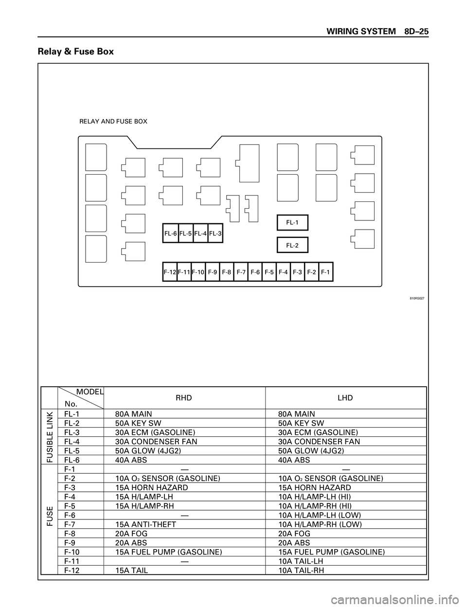
Relay & Fuse Box
FL-1
FL-2 FL-6 FL-5 FL-4 FL-3
F-12 F-11 F-10 F-9 F-8 F-7 F-6 F-5 F-4 F-3 F-2 F-1 RELAY AND FUSE BOX
RHD
FUSIBLE LINK FUSE
MODEL
No.
FL-1
FL-2
FL-3
FL-4
FL-5
FL-6
F-1
F-2
F-3
F-4
F-5
F-6
F-7
F-8
F-9
F-10
F-11
F-12LHD
80A MAIN
50A KEY SW
30A ECM (GASOLINE)
30A CONDENSER FAN
50A GLOW (4JG2)
40A ABS
10A O
2 SENSOR (GASOLINE)
15A HORN HAZARD
15A H/LAMP-LH
15A H/LAMP-RH
15A ANTI-THEFT
20A FOG
20A ABS
15A FUEL PUMP (GASOLINE)
15A TAIL80A MAIN
50A KEY SW
30A ECM (GASOLINE)
30A CONDENSER FAN
50A GLOW (4JG2)
40A ABS
10A O2 SENSOR (GASOLINE)
15A HORN HAZARD
10A H/LAMP-LH (HI)
10A H/LAMP-RH (HI)
10A H/LAMP-LH (LOW)
10A H/LAMP-RH (LOW)
20A FOG
20A ABS
15A FUEL PUMP (GASOLINE)
10A TAIL-LH
10A TAIL-RH —
—
——
810RS027
Page 2624 of 3573

WIRING SYSTEM 8DÐ31
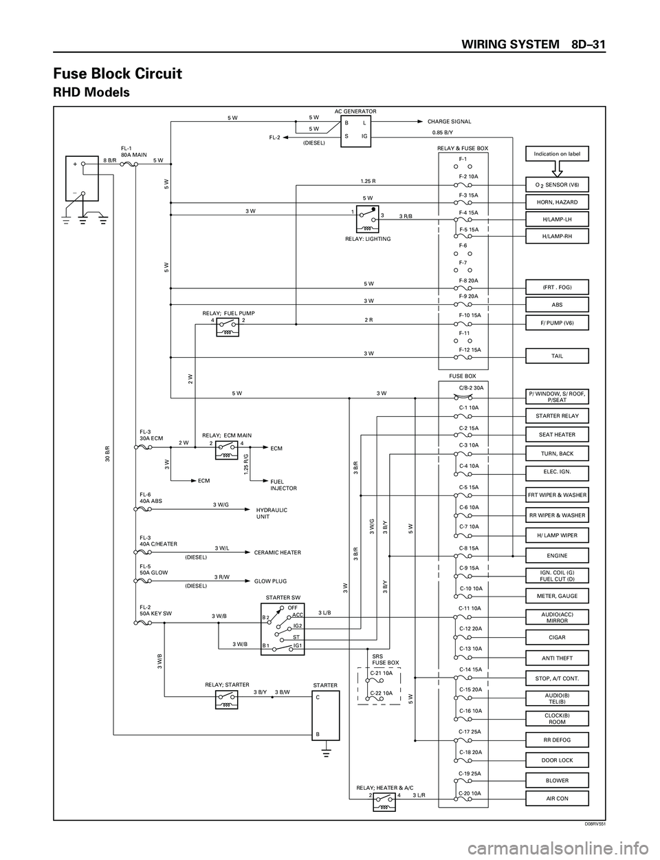
Fuse Block Circuit
RHD Models
Indication on label
BOFF
STIG2 ACC
STARTER SW
+
_
O SENSOR (V6)
HORN, HAZARD
H/LAMP-LH
H/LAMP-RH
(FRT . FOG)
ABS
F/ PUMP (V6)
P/ WINDOW, S/ ROOF,
P/SEAT
STARTER RELAY
TURN, BACK
ELEC. IGN.
FRT WIPER & WASHER
RR WIPER & WASHER
H/ LAMP WIPER
ENGINE
IGN. COIL (G)
FUEL CUT (D)
METER, GAUGE
AUDIO(ACC)
MIRROR
CIGAR
STOP, A/T CONT.
AUDIO(B)
TEL(B)
CLOCK(B)
ROOM
RR DEFOG
DOOR LOCK
IG1B
STARTER
C
B
AC GENERATOR
BL
IG
F-1
F-2 10A
F-3 15A
F-4 15A
F-5 15A
F-8 20A
F-9 20A
F-10 15A
C/B-2 30A
C-1 10A
C-3 10A
C-4 10A
C-5 15A
C-6 10A
C-7 10A
C-8 15A
C-9 15A
C-10 10A
C-11 10A
C-12 20A
C-14 15A
C-15 20A
C-16 10A
C-17 25A
C-18 20A RELAY; STARTERCHARGE SIGNAL
FUSE BOX
RELAY; ECM MAIN
FUEL
INJECTOR ECM
HYDRAULIC
UNIT FL-3
30A ECM
FL-6
40A ABS
FL-2
50A KEY SW FL-1
80A MAIN2
2
1
5 W
5 W
8 B/R 5 W
F-6
F-7
F-11
RELAY & FUSE BOX
C-2 15A
BLOWERC-19 25A
C-20 10A
5 W 5 W
5 W
1.25 R
5 W
5 W
3 W
2 R
3 W
3 B/R
3 W
3 W/G
3 B/Y 3 B/Y
5 W 5 W
3 B/W
3 W/B
3 W/B 3 W/B3 W/G 2 W
30 B/R
0.85 B/Y
3 L/B
3 W
1.25 R/G
SFL-2
(DIESEL)
SEAT HEATER
FL-3
40A C/HEATER
FL-5
50A GLOW
CERAMIC HEATER
(DIESEL)
GLOW PLUG
(DIESEL)
31
3 R/B3 W
24
3 W/L
3 R/W
ANTI THEFTC-13 10A
3 B/Y
RELAY: LIGHTING
3 B/R
RELAY; FUEL PUMP
42
TAIL
5 W
2 W
AIR CON
RELAY; HEATER & A/C
24
3 W
3 L/R
C-21 10ASRS
FUSE BOX
C-22 10A
F-12 15A
ECM
D08RV551
Page 2625 of 3573

8DÐ32 WIRING SYSTEM
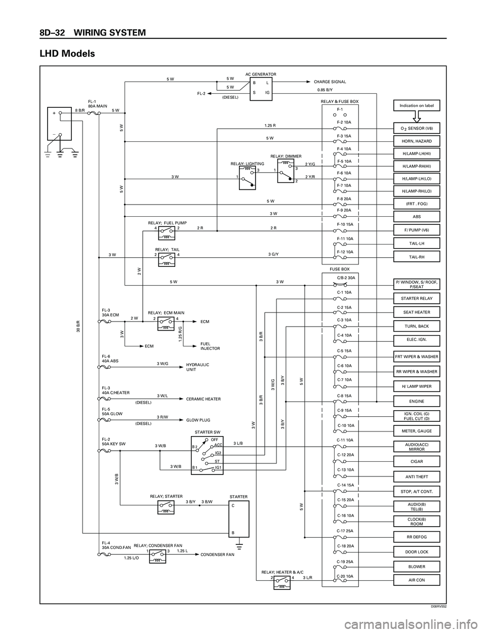
LHD Models
FL-4
30A COND.FAN
Indication on label
BOFF
STIG2 ACC
STARTER SW
+
_
O SENSOR (V6)
HORN, HAZARD
H/LAMP-LH(HI)
H/LAMP-RH(HI)
(FRT . FOG)
ABS
F/ PUMP (V6)
P/ WINDOW, S/ ROOF,
P/SEAT
STARTER RELAY
TURN, BACK
ELEC. IGN.
FRT WIPER & WASHER
RR WIPER & WASHER
H/ LAMP WIPER
ENGINE
IGN. COIL (G)
FUEL CUT (D)
METER, GAUGE
AUDIO(ACC)
MIRROR
CIGAR
STOP, A/T CONT.
AUDIO(B)
TEL(B)
CLOCK(B)
ROOM
RR DEFOG
DOOR LOCK
IG1B
STARTER
C
B
AC GENERATOR
BL
IG
F-1
F-2 10A
F-3 15A
F-4 10A
F-5 10A
F-8 20A
F-9 20A
F-10 15A
C/B-2 30A
C-1 10A
C-3 10A
C-4 10A
C-5 15A
C-6 10A
C-7 10A
C-8 15A
C-9 15A
C-10 10A
C-11 10A
C-12 20A
C-14 15A
C-15 20A
C-16 10A
C-17 25A
C-18 20A RELAY; STARTERCHARGE SIGNAL
FUSE BOX
RELAY; ECM MAIN
FUEL
INJECTOR ECM
HYDRAULIC
UNIT FL-3
30A ECM
FL-6
40A ABS
FL-2
50A KEY SW FL-1
80A MAIN2
2
1
ECM
5 W
5 W
8 B/R 5 W
F-6 10A
F-7 10A
F-11 10A RELAY & FUSE BOX
C-2 15A
BLOWERC-19 25A
C-20 10A
5 W 5 W
5 W
1.25 R
5 W
5 W
2 R 2 R3 W
3 B/R
3 W
3 W/G
3 B/Y 3 B/Y
5 W 5 W
3 B/W
3 W/B
3 W/B 3 W/B3 W/G 2 W
30 B/R
0.85 B/Y
3 L/B
3 W
1.25 R/G
SFL-2
(DIESEL)
SEAT HEATER
FL-3
40A C/HEATER
FL-5
50A GLOW
CERAMIC HEATER
(DIESEL)
GLOW PLUG
(DIESEL)
3 W
3 W
24
3 W/L
3 R/W
ANTI THEFTC-13 10A
3 B/Y
3 B/R
RELAY; FUEL PUMP
42
TAIL-RH
3 G/Y
5 W
2 W
AIR CON
RELAY; HEATER & A/C
24
3 W
3 L/R
F-12 10ARELAY; TAIL
24H/LAMP-LH(LO)
H/LAMP-RH(LO)
3
1
2 Y/R RELAY: DIMMER2 Y/G
2
3
1RELAY: LIGHTING
TAIL-LH
RELAY; CONDENSER FAN
131.25 L
1.25 L/O
CONDENSER FAN
D08RV552