Oil JAGUAR X308 1998 2.G Workshop Manual
[x] Cancel search | Manufacturer: JAGUAR, Model Year: 1998, Model line: X308, Model: JAGUAR X308 1998 2.GPages: 2490, PDF Size: 69.81 MB
Page 879 of 2490

Engine - Variable Camshaft Timing Oil Control Unit LH
In-vehicle Repair
Removal
Special Tool(s)
Camshaft setting
303-530
Timing chain tensioning
303-532
Wedges, primary chain
303-533
Crankshaft setting
303-531
1. Open the engine compartment and fit paintwork protection
sheets.
2. Set the engine compartment cover to the service access
position.
3. Disconnect the batt ery ground cable.
пЃ¬Remove the battery cover.
4. Remove the Timing Co ver. Refer to Operation 12.65.01 in this
Section.
5. Remove the Variable Valve Ti ming Bush Carrier Assembly.
Refer to Operation 12.65.52 in this Section
6. Raise the vehicle on a ramp.
7. Remove the crankshaft position sensor.
Page 885 of 2490

Engine - Variable Camshaft Timing Oil Control Unit RH
In-vehicle Repair
Removal
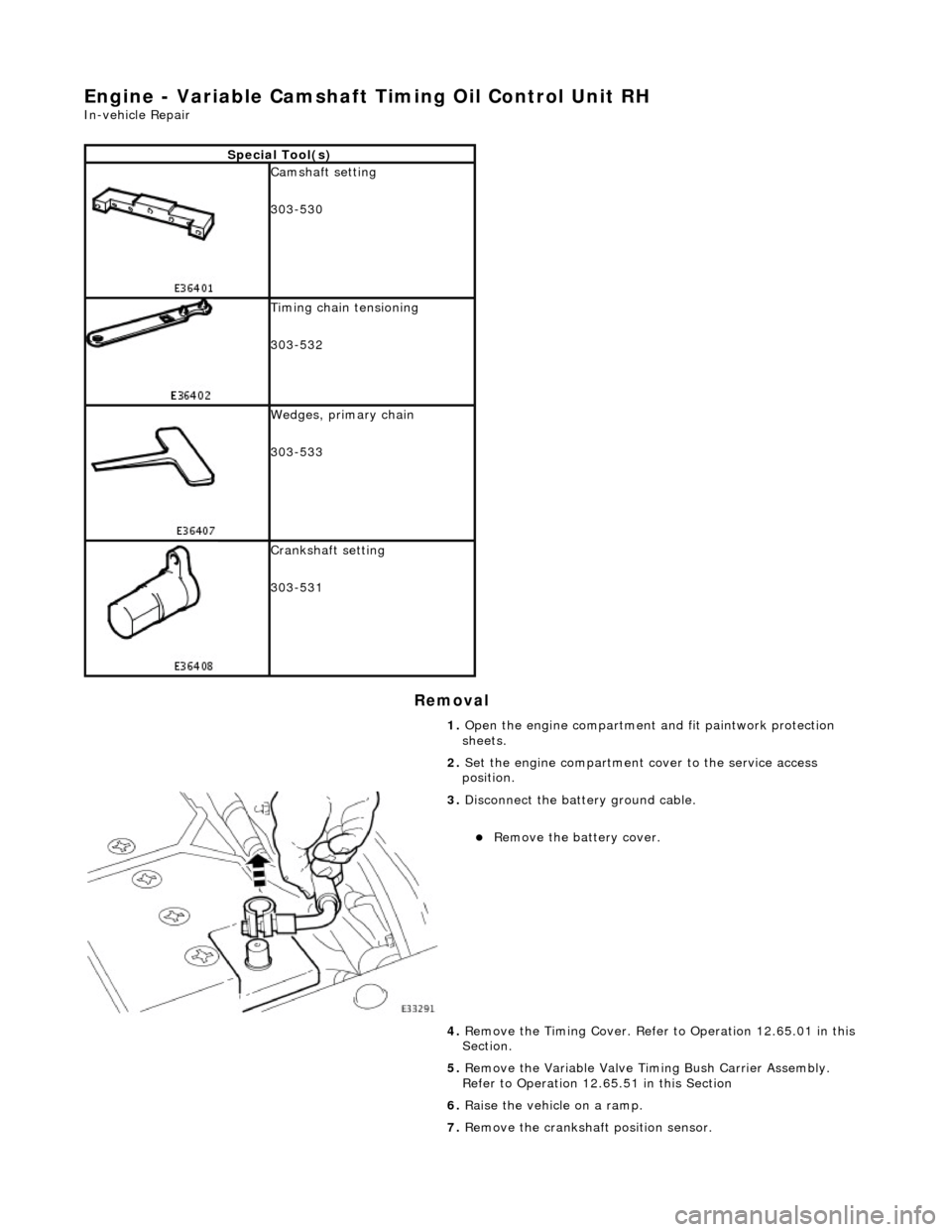
Special Tool(s)
Camshaft setting
303-530
Timing chain tensioning
303-532
Wedges, primary chain
303-533
Crankshaft setting
303-531
1. Open the engine compartment and fit paintwork protection
sheets.
2. Set the engine compartment cover to the service access
position.
3. Disconnect the batt ery ground cable.
пЃ¬Remove the battery cover.
4. Remove the Timing Co ver. Refer to Operation 12.65.01 in this
Section.
5. Remove the Variable Valve Ti ming Bush Carrier Assembly.
Refer to Operation 12.65.51 in this Section
6. Raise the vehicle on a ramp.
7. Remove the crankshaft position sensor.
Page 891 of 2490

Engine - Variable Camshaft Timing Oil Control Unit Housing LH
In-vehicle Repair
Removal
Installation
1. Open the engine compartment and fit paintwork protection
sheets.
2. Set the engine compartment cover to the service access
position.
3. Disconnect the batt ery ground cable.
пЃ¬Remove the battery cover.
4. Remove the Timing Co ver. Refer to Operation 12.65.01 in this
Section.
5. Remove the VVT bush carrier.
1. Remove the two bolts and one nut which secure the carrier to the cylinder block.
2. Release the carrier from the two ring dowels and
remove it.
6. Remove the seals from the bush carrier.
1. Remove the sealing ring (scarf jointed) from the
carrier bush groove.
2. Remove the O-ring from the carrier oil-way recess.
7. Clean and inspect all relevant components.
1. Fit new seals to the bush carrier.
1. Fit the new sealing ring (scarf jointed) to the carrier bush groove.
2. Fit a new O-ring to the carrier oil-way.
Page 893 of 2490

V
ariable Camshaft Timing Oil Control Unit Housing RH
12.65.51
Removal
1. Open the engine compartment and fit paintwork protection sheets.
2. Set the engine compartment cover to the service access position.
3
. Disconnect the battery ground cable.
п‚·пЂ Remove the battery cover.
4. Remove the Timing Cover. Refer to Operation <<12.65.01>>
in this Section.
5
. Remove the VVT bush carrier.
1. Remove the three bolts which secure the carrier to the cylinder block.
Page 894 of 2490

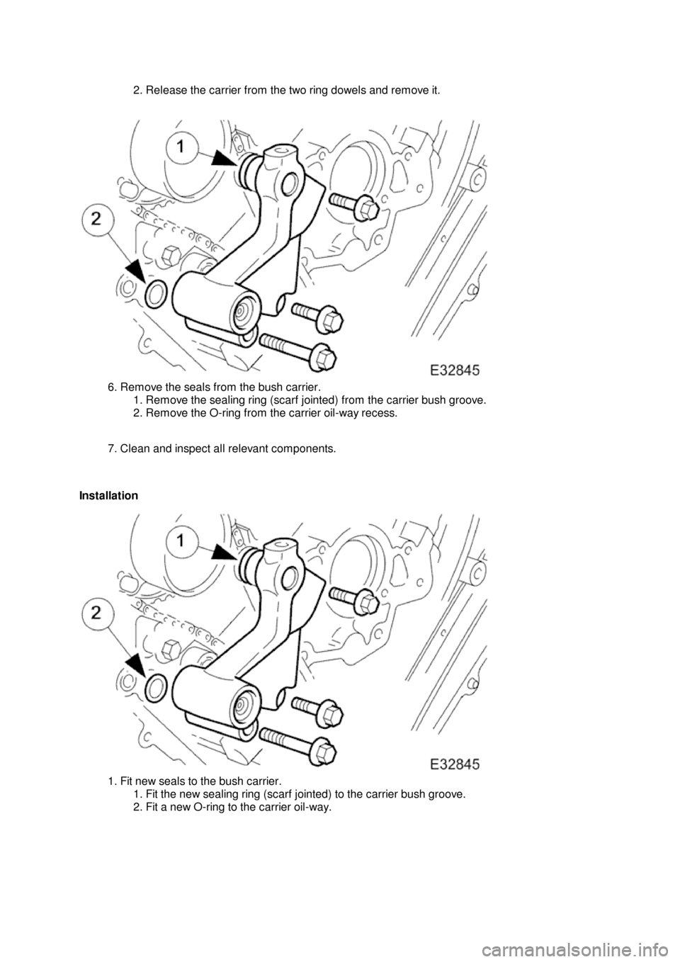
2.
Release the carrier from the two ring dowels and remove it.
6.
Remove the seals from the bush carrier.
1. Remove the sealing ring (scarf jointed) from the carrier bush groove.
2. Remove the O-ring from the carrier oil-way recess.
7. Clean and inspect all relevant components.
Installation
1.
Fit new seals to the bush carrier.
1. Fit the new sealing ring (scarf jointed) to the carrier bush groove.
2. Fit a new O-ring to the carrier oil-way.
Page 901 of 2490

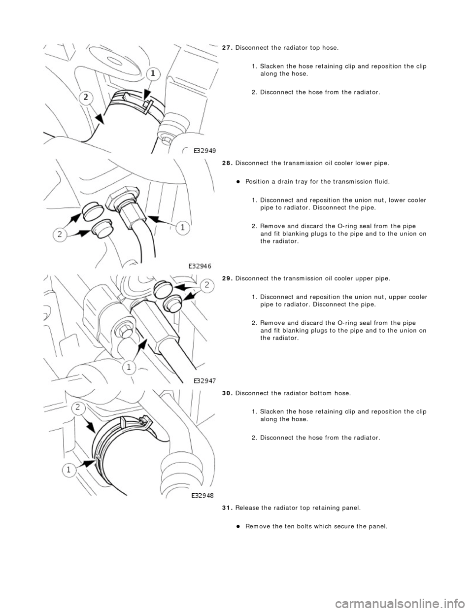
27. Disconnect the radiator top hose.
1. Slacken the hose retaining clip and reposition the clip
along the hose.
2. Disconnect the hose from the radiator.
28. Disconnect the transmission oil cooler lower pipe.
пЃ¬Position a drain tray for the transmission fluid.
1. Disconnect and reposition the union nut, lower cooler pipe to radiator. Di sconnect the pipe.
2. Remove and discard the O- ring seal from the pipe
and fit blanking plugs to the pipe and to the union on
the radiator.
29. Disconnect the transmission oil cooler upper pipe.
1. Disconnect and reposition the union nut, upper cooler pipe to radiator. Di sconnect the pipe.
2. Remove and discard the O- ring seal from the pipe
and fit blanking plugs to the pipe and to the union on
the radiator.
30. Disconnect the radiator bottom hose.
1. Slacken the hose retaining clip and reposition the clip
along the hose.
2. Disconnect the hose from the radiator.
31. Release the radiator top retaining panel.
пЃ¬Remove the ten bolts which secure the panel.
Page 904 of 2490

41. Raise the vehicle on the ramp.
42. Drain the engine oil.
1. Position the waste oil bowser.
2. Remove the sump drain pl ug and drain the engine oil.
пЃ¬Wipe the drain plug and refit it to the sump to prevent oil
dripping.
пЃ¬Move the oil bowser away from the vehicle.
43. Move the front muffler forwar d to allow the intermediate
mufflers to be displaced.
пЃ¬Slacken the clamps (left-hand and right-hand sides),
catalytic converter to front muffler.
44. Slacken the clamps (left-han d and right-hand sides),
intermediate mufflers to front muffler.
45. Remove the front muffler.
пЃ¬Disconnect the front muffler from the intermediate
mufflers and then from the downpipe catalytic converters.
46. Remove the downpipe catalytic converters.
Page 905 of 2490

пЃ¬Remove the bolts which secure the downpipe to the lower
mounting bracket.
пЃ¬Remove the downpipe assembly.
пЃ¬Repeat the above operations for the other downpipe
catalytic converter.
47. Remove the two bolts which secure each mounting bracket to
the bell housing and remove the brackets.
48. Disconnect the driveshaft (propshaft) flange from the
transmission output flange.
пЃ¬Remove the three bolts which secure the flange. Rotate
the shaft for access to each bolt.
пЃ¬Disconnect the shaft and reposition it to the side.
49. Remove the securing bolt and disconnect the ground lead
from the transmission casing.
50. Disconnect the oil cooler pi pes (where fitted) from the
engine.
1. Remove the bolt which secures the pipe clamping
plate. Remove the clamping plate.
2. Place a drain tray beneat h the pipes and disconnect
Page 906 of 2490

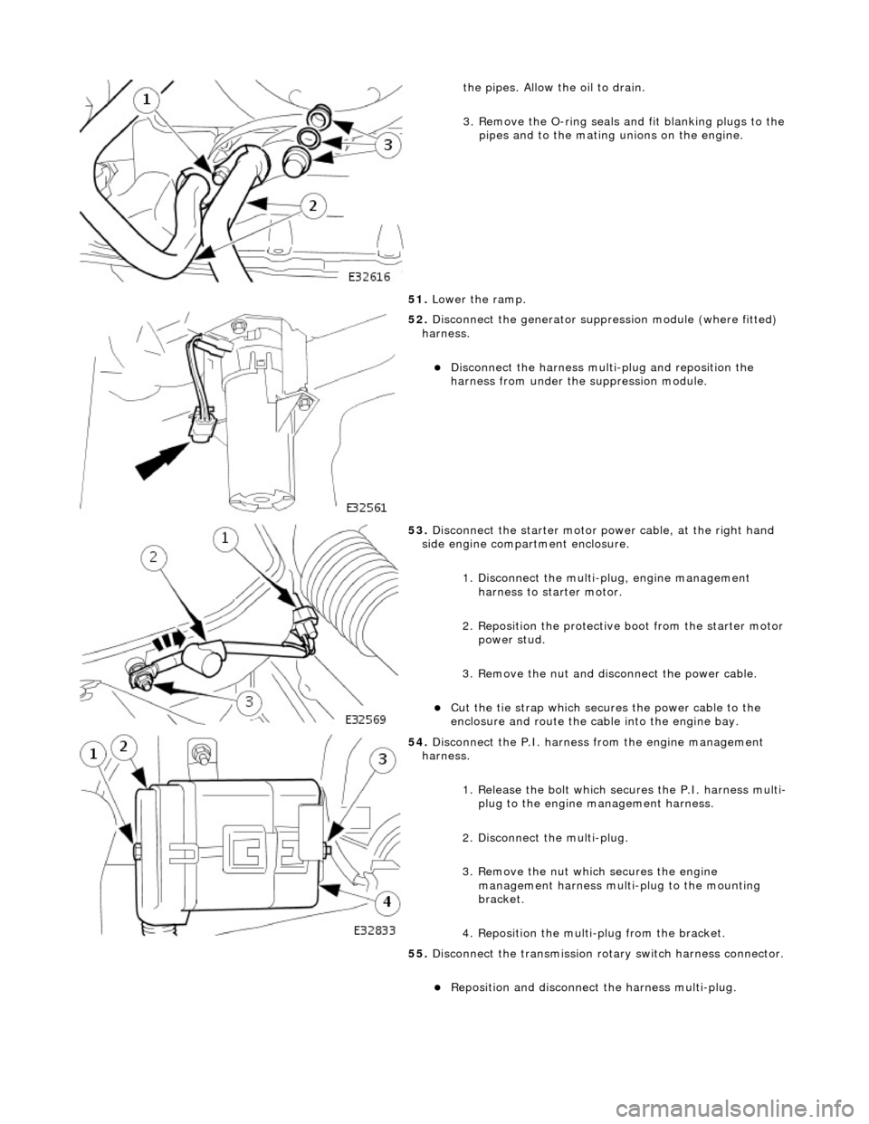
the pipes. Allow the oil to drain.
3. Remove the O-ring seals and fit blanking plugs to the
pipes and to the mating unions on the engine.
51. Lower the ramp.
52. Disconnect the generator suppres sion module (where fitted)
harness.
пЃ¬Disconnect the harness multi-plug and reposition the
harness from under the suppression module.
53. Disconnect the starter motor power cable, at the right hand
side engine compartment enclosure.
1. Disconnect the multi-plug, engine management harness to starter motor.
2. Reposition the protective boot from the starter motor
power stud.
3. Remove the nut and disc onnect the power cable.
пЃ¬Cut the tie strap which secures the power cable to the
enclosure and route the cable into the engine bay.
54. Disconnect the P.I. harness from the engine management
harness.
1. Release the bolt which secures the P.I. harness multi-plug to the engine management harness.
2. Disconnect the multi-plug.
3. Remove the nut which secures the engine management harness multi-plug to the mounting
bracket.
4. Reposition the multi-plug from the bracket.
55. Disconnect the transmission rota ry switch harness connector.
пЃ¬Reposition and disconnect the harness multi-plug.
Page 915 of 2490

пЃ¬Connect
the front muffler to
the intermediate muffler,
noting the alignment of the indicator rings.
пЃ¬W
ith the front muffler positioned correctly, tighten the
clamps (left-hand and right-hand sides) to the catalytic
converter.
21
.
Tighten the clamps (left-hand and right-hand sides),
intermediate mufflers to front muffler.
22
.
Tighten the downpipe bracket se curing bolts to the correct
torque
23
.
Connect the oil cooler pipes (w here fitted) to the engine.
1. Remove the blanking plugs from the pipes and from the mating unions on the engine.
2. Fit new O-ring seals to the pipes and lubricate with new engine oil.
3. Connect the pipes to the engine and fit the clamping
plate and bolt.
24. Lower the vehicle on the ramp.
25. Connect the heater and brake servo hoses.
1. Connect the heat er return hose.
2. Connect the heater feed hose and secure the locking
lever.