Oil JAGUAR X308 1998 2.G Workshop Manual
[x] Cancel search | Manufacturer: JAGUAR, Model Year: 1998, Model line: X308, Model: JAGUAR X308 1998 2.GPages: 2490, PDF Size: 69.81 MB
Page 1342 of 2490
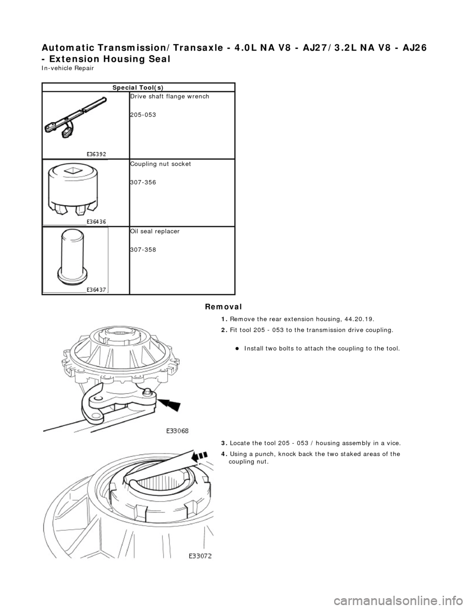
Automatic Transmission/Transaxle - 4.0L NA V8 - AJ27/3.2L NA V8 - AJ26
- Extension Housing Seal
In-vehicle Repair
Removal
Special Tool(s)
Drive shaft flange wrench
205-053
Coupling nut socket
307-356
Oil seal replacer
307-358
1. Remove the rear extension housing, 44.20.19.
2. Fit tool 205 - 053 to the transmission drive coupling.
пЃ¬Install two bolts to attach the coupling to the tool.
3. Locate the tool 205 - 053 / housing assembly in a vice.
4. Using a punch, knock back the two staked areas of the
coupling nut.
Page 1343 of 2490
Installation
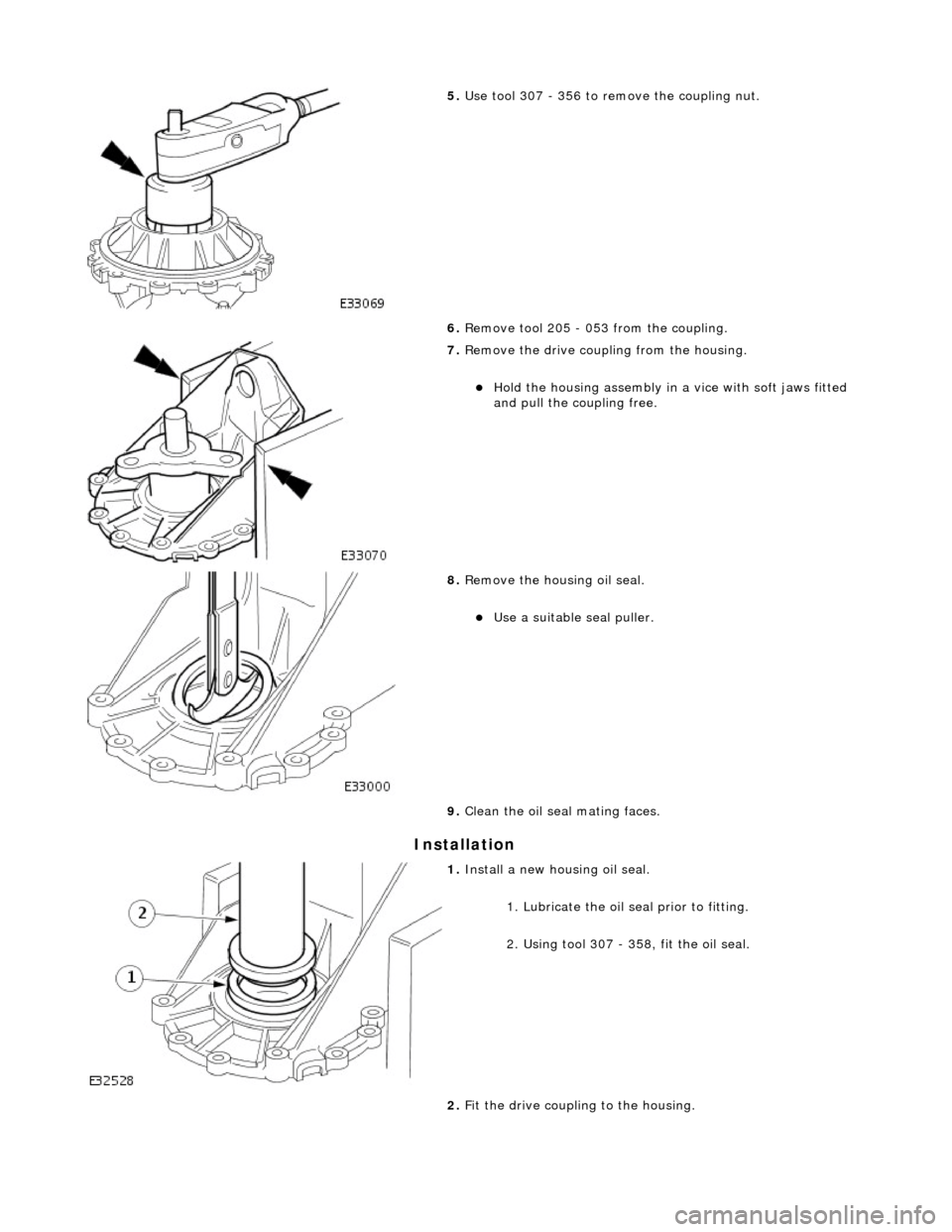
5. Use tool 307 - 356 to remove the coupling nut.
6. Remove tool 205 - 053 from the coupling.
7. Remove the drive coupling from the housing.
пЃ¬Hold the housing assembly in a vice with soft jaws fitted
and pull the co upling free.
8. Remove the housing oil seal.
пЃ¬Use a suitable seal puller.
9. Clean the oil seal mating faces.
1. Install a new housing oil seal.
1. Lubricate the oil se al prior to fitting.
2. Using tool 307 - 358, fit the oil seal.
2. Fit the drive coupling to the housing.
Page 1381 of 2490

Automatic Transmission/Transaxle - 4.0L NA V8 - AJ27/3.2L NA V8 - AJ26
- Input Shaft Seal
Disassembly and Assembly of Subassemblies
Special Tool(s)
Oil seal replacer
307-357
1. Remove the transmission unit, 44.20.01.
2. Remove the torque converter from the transmission unit,
44.17.07.
3. Remove the front pump seal.
пЃ¬Remove and discard the seal retaining snap-ring.
пЃ¬Using a 'Snap-on' oil seal puller, remove and discard the
seal.
4. Clean the seal housing.
5. Installation is th e reverse of the re moval procedure.
6. Use tool 307 - 357 to install the seal.
пЃ¬Lubricate the seal pr ior to fitting.
Page 1382 of 2490

Automatic Transmission/Transaxle - 4.0L NA V8 - AJ27/3.2L NA V8 - AJ26
- Torque Converter
Disassembly and Assembly of Subassemblies
Special Tool(s)
Lifting handle
307-139
1. Remove the transmission unit from the vehicle; 44.20.01.
2. Remove the torque converter from the transmission unit.
пЃ¬Install lifting handles 307 - 139.
3. Remove lifting handles 307 - 139 from the torque converter.
4. Clean the torque conver ter and mating faces.
5. CAUTIONS:
Use extreme care NOT to damage the oil seal with the
converter spigot.
Ensure that the conver ter is fully located.
Install the torque converter.
1. Install lifting handles 307 - 139.
2. Lubricate the front pump seal.
пЃ¬To facilitate location, rotate the converter as it is being
fitted and note the engagement of splines and oil pump
drive.
6. Check that the three conver ter fixing boss faces are
approximately 8,0 mm proud of the transmission mounting
face.
7. Remove lifting handles 307 - 139 from the torque converter.
8. Install the transmission unit; refer to Operation 44.20.01,
noting especially the alignment instructions.
Page 1391 of 2490
In the event of a system fault, the TCM will adopt 'limp home' mode.
Electrical control
Refer to Section 307-01B.
Transmission Control Components
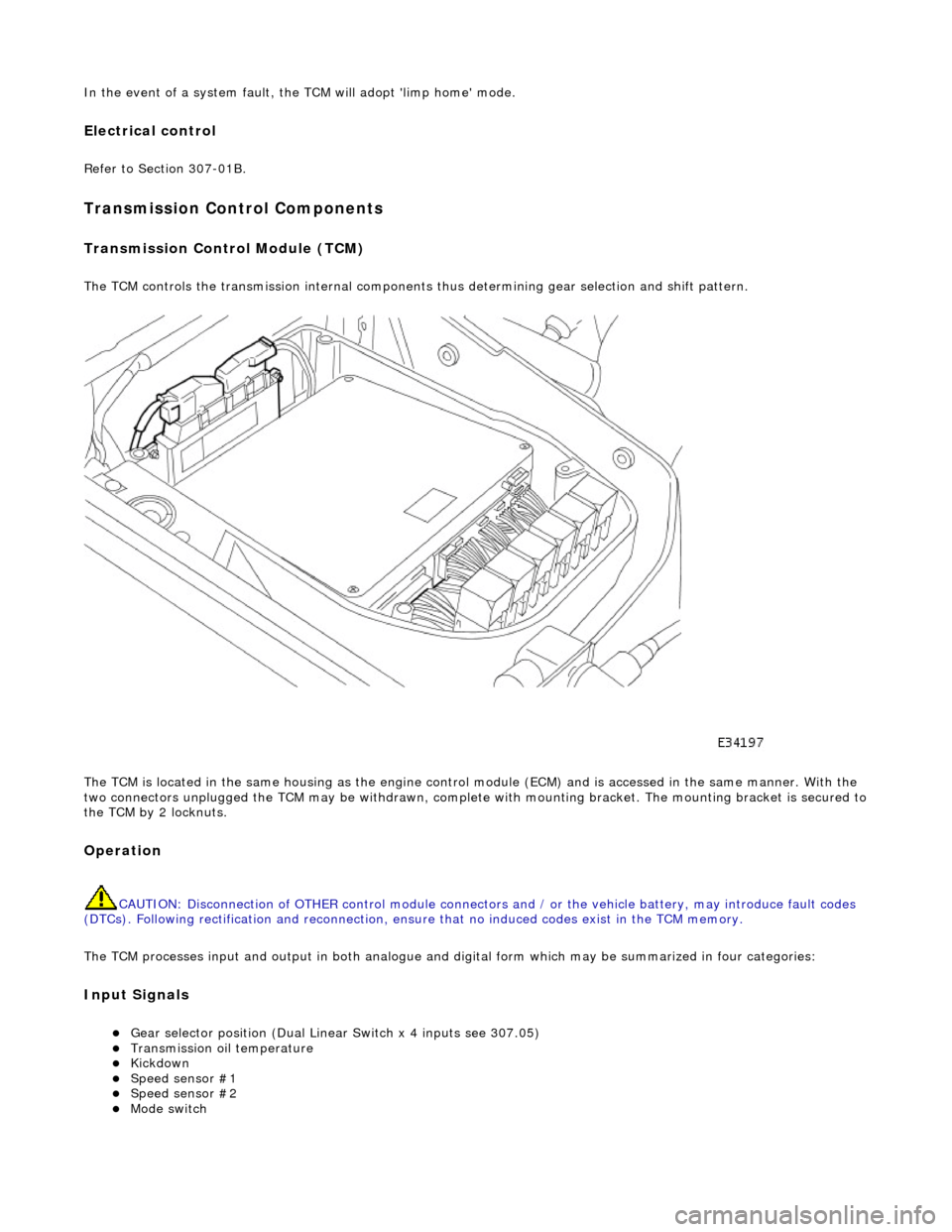
Transmission Control Module (TCM)
The TCM controls the transmission internal components thus determining gear selection and shift pattern.
The TCM is located in the same housing as the engine control module (ECM) and is accessed in the same manner. With the
two connectors unplugged the TCM may be withdrawn, complete with mounting bracket. The mounting bracket is secured to
the TCM by 2 locknuts.
Operation
CAUTION: Disconnection of OTHER contro l module connectors and / or the vehicle battery, may introduce fault codes
(DTCs). Following rectification and reconnection, ensu re that no induced codes exist in the TCM memory.
The TCM processes input and output in both analogue and di gital form which may be summarized in four categories:
Input Signals
пЃ¬Gear selector position (Dual Linear Switch x 4 inputs see 307.05) пЃ¬Transmission oil temperature пЃ¬Kickdown пЃ¬Speed sensor #1 пЃ¬Speed sensor #2 пЃ¬Mode switch
Page 1392 of 2490
CAN Input Signals
пЃ¬Traction status пЃ¬ABS malfunction пЃ¬ABS status пЃ¬Engine torque status пЃ¬Throttle position пЃ¬Accelerator pedal position пЃ¬Engine torque reduction confirmation пЃ¬Engine speed пЃ¬Engine coolant temperature пЃ¬Cruise status пЃ¬OBDII fault code clear request пЃ¬Throttle malfunction warning RED or AMBER пЃ¬All road wheel speeds пЃ¬Token for network status ECM пЃ¬Token for network status INST пЃ¬Token for network status ABS пЃ¬Diagnostic data in from external device (PDU)
Output Signals
пЃ¬Solenoid valve 1 <-> 2 and 4 <-> 5 shift пЃ¬Solenoid valve 2 <-> 3 shift пЃ¬Solenoid valve 3 <-> 4 shift пЃ¬Solenoid valve converter lock-up clutch пЃ¬Control valve - modulating pressure пЃ¬Control valve - shift pressure
CAN Output Signals
пЃ¬Engine torque reduction request пЃ¬MIL status (whether present DTC should operate MIL) пЃ¬Transmission input speed пЃ¬Transmission output speed пЃ¬Converter slip пЃ¬Kickdown status пЃ¬Gear position (actual) пЃ¬Gear position (selected) пЃ¬Gear selection fault пЃ¬Converter lock-up status пЃ¬Current selected shift map пЃ¬Transmission oil temperature пЃ¬Transmission malfunction пЃ¬Pecus flag (state of current TCM program) пЃ¬Target for next gear position пЃ¬Gear shift torque transfer progress at shift пЃ¬MIL status (response to activate the MIL relevant to a DTC) пЃ¬OBDII fault code clear acknowledgement пЃ¬Transmission DTCs (P codes) пЃ¬Token for network status TCM пЃ¬Diagnostic data out to external device (PDU)
Emergency Running (elect ronic limp-home mode)
The TCM constantly monitors the transmissi on for faults. In the event of a problem the TCM will adopt the limp-home mode, in which the gear currently held remains engaged, until P is selected. The modulati ng and shift pressures will increase to
maximum and converter lock-up will be inhibited.
Following the selection of P , the only ratios available will be 2 (irrespective of forward ratio manual selection) and R .
With the vehicle at rest, the procedure to manually select is as follows:
1. 1. Select P .
Page 1395 of 2490
and/or increased performance as appropriate.
Serial Communications Interfaces
Controller Area Network (CAN)
The TCM is an integral part of the CAN system which facilita tes the interchange of real-time data between control modules
and sensors; refer to 303-14 fo r a full description of CAN.
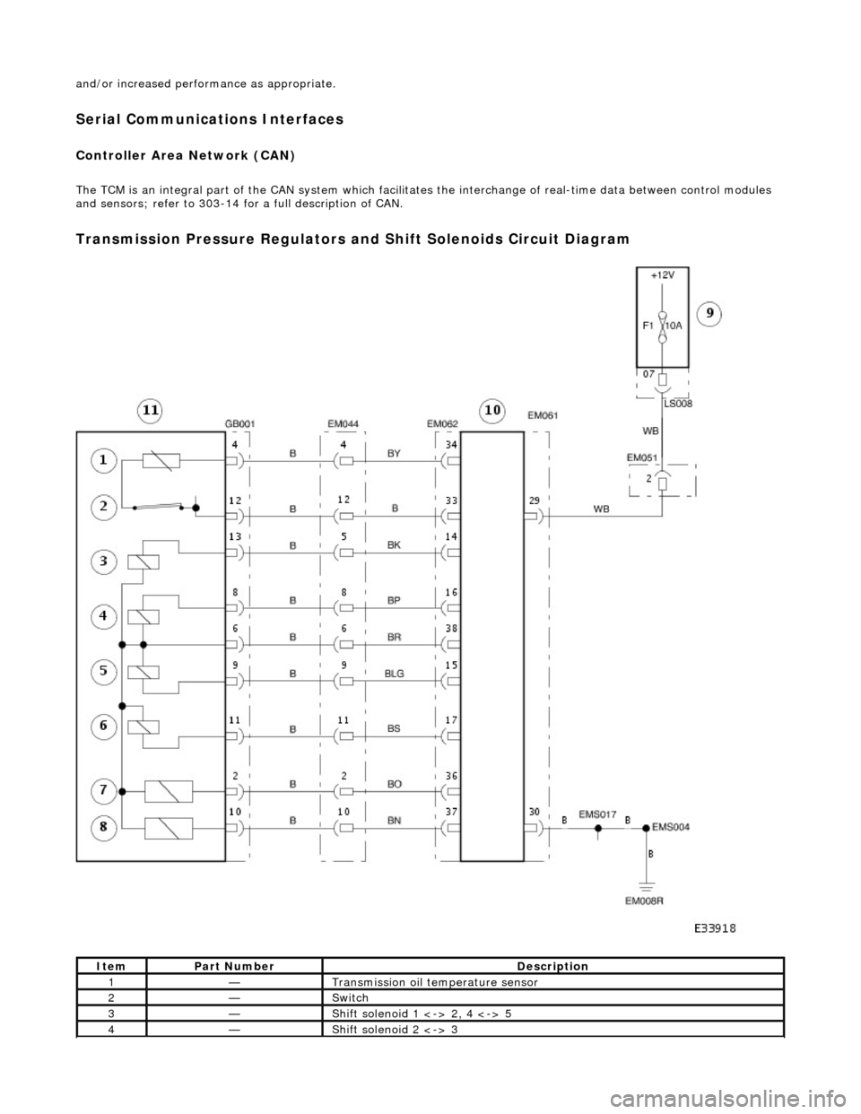
Transmission Pressure Regulators and Shift Solenoids Circuit Diagram
ItemPart NumberDescription
1—Transmission oil temperature sensor
2—Switch
3—Shift solenoid 1 <-> 2, 4 <-> 5
4—Shift solenoid 2 <-> 3
Page 1401 of 2490

Pinpoint test A: P0740
DTC P0730 Incorrect gear ratioEngaged gear implausible / transmission
slipping Oil level low
Valve body assembly faulty
Transmission faulty
*
*
*
*GO to Pinpoint Test H *
DTC P0780 Shift malfunctionValve body assembly faulty
Transmission faulty
*
*GO to Pinpoint Test H *
PINPOINT TEST A : P0740
TEST CONDITIONSDETAILS/RESULTS/ACTIONS
A1: RETRIEVE DTCS
• NOTE: Battery and or ECM disconnection prior to scanning wi
ll erase all data, ensure that the correct DTC is present.
Connect the scan tool 1
Have the DTC(s) and freeze frame data been recorded?
Yes GO to A2
A2: CHECK TORQUE CONVERTER CLUTCH SOLENOID RESISTANCE
With, EM062 disconnected, measure the resistance between 1
Page 1433 of 2490

Automatic Transmission/Transaxle - 4.0L SC V8 - AJ26 - Extension
Housing Seal
In-vehicle Repair
Removal
Special Tool(s)
Oil seal replacer
307-378
Driveshaft wrench
205-053
1. Disconnect the battery ground lead.
2. Select N and choc the road wheels.
3. Remove the front muffler, re fer to Operation 30.10.18.
4. Remove the engine rear mounting bracket.
1. Support the transmission.
2. Remove the bolt, engine rear mounting to transmission.
3. Remove the four bolts which secure the mounting
cross member to the body.
5. Detach the driveshaft from th e transmission drive flange.
1. If the transmission is to be refitted, mark the position of the coupling relative to the drive flange.
5. CAUTION: Under no circ umstances remove the
driveshaft to flexible coupling fixings.
2. Remove the three bolts, tr ansmission drive flange to
flexible coupling.
6. Secure the driveshaft wrench 205 - 053 to the output shaft
flange.
Page 1434 of 2490
Installation
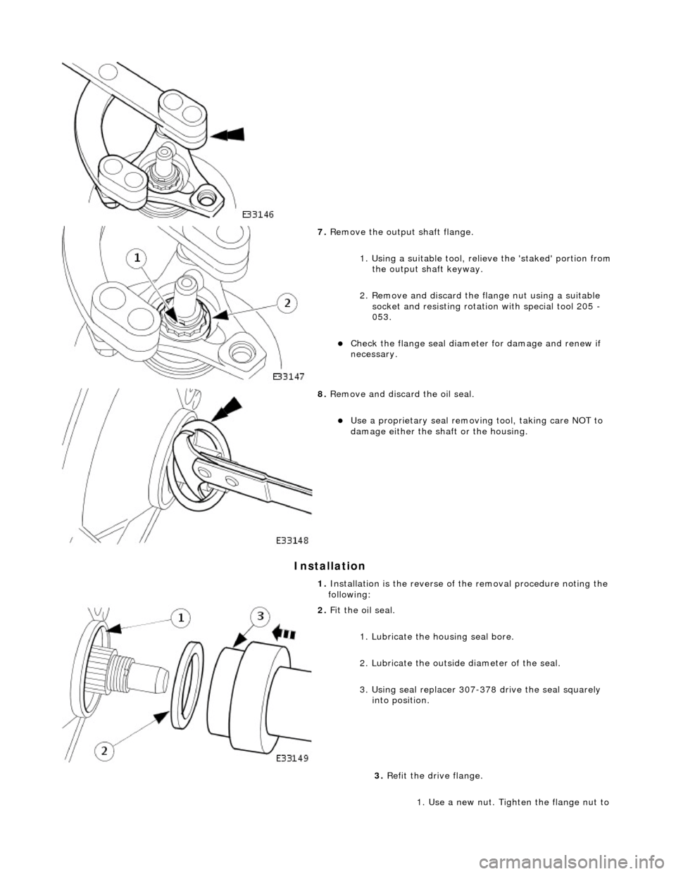
7. Remove the output shaft flange.
1. Using a suitable tool, reli eve the 'staked' portion from
the output shaft keyway.
2. Remove and discard the fl ange nut using a suitable
socket and resisting rotation with special tool 205 -
053.
пЃ¬Check the flange se al diameter for damage and renew if
necessary.
8. Remove and discard the oil seal.
пЃ¬Use a proprietary seal removing tool, taking care NOT to
damage either the shaft or the housing.
1. Installation is the re verse of the removal procedure noting the
following:
2. Fit the oil seal.
1. Lubricate the housing seal bore.
2. Lubricate the outside diameter of the seal.
3. Using seal replacer 307-378 drive the seal squarely into position.
3. Refit the drive flange.
1. Use a new nut. Tighten the flange nut to