check engine light JAGUAR XFR 2010 1.G Workshop Manual
[x] Cancel search | Manufacturer: JAGUAR, Model Year: 2010, Model line: XFR, Model: JAGUAR XFR 2010 1.GPages: 3039, PDF Size: 58.49 MB
Page 103 of 3039
General Information - Road/Roller Testing
Description and Operation Published: 11-May-2011
Road or roller testing may be carried out for various reasons and a procedure detailing pre-test checks, through engine starting
and stopping, pre-driving checks, on-test checks to final checks on completion of the test is given in this section.
Unless complete vehicle performance is being checked, the full road test procedure need not be carried out. Instead, those
items particularly relevant to the system/s being checked can be extracted.
Pre - Test Checks
WARNING: If the brake system hydraulic fluid level is low, pedal travel is excessive or a hydraulic leak is found, do not
attempt to road test the vehicle until the reason for the low fluid level, excessive pedal travel or hydraulic leak is found and
rectified.
It is suggested that pre-test checks, and functional tests of those systems/circuits which affect the safe and legal operations
of the vehicle, such as brakes, lights and steering, should always be carried out before the road or roller test.
Engine oil level
Engine coolant level
Tires, for correct pressure, compatible types and tread patterns, and wear within limits
There is sufficient fuel in the tank to complete the test
All around the engine, transmission and under the vehicle for oil, coolant, hydraulic and fuel leaks. Make a note of any
apparent leaks and wipe off the surrounding areas to make it easier to identify the extent of the leak on completion of
the test
Starting the Engine
CAUTION: On initial drive away from cold and within the first 1.5 km (1 mile), do not depress accelerator pedal beyond
half travel until the vehicle has attained a minimum speed of 25 km/h (15 miles/h). Never operate at high engine speed or
with the accelerator pedal at full travel whilst the engine is cold.
With the ignition switched off, check:
The parking brake is applied
The transmission selector lever is in Park
All instrument gauges (except fuel gauge) read zero
With the ignition switched on, check:
Ignition controlled warning lamps come on
Engine coolant temperature gauge registers a reading compatible with the engine coolant temperature
Fuel gauge registers a reading appropriate to the fuel level in the tank
The operation of the parking brake and brake fluid level warning lamps
On Road or Roller Test Check:
CAUTION: If road testing, check the brake operation while still travelling at low speed before continuing with the test. If
the brakes pull to one side, or appear to be otherwise faulty, do not continue with the road test until the fault has been found
and rectified.
Initial gear engagement is smooth
Parking brake control operates smoothly and the parking brake releases quickly and completely
Transmission takes up the drive smoothly, without judder
The engine power output is satisfactory, full power is achieved, acceleration is smooth and pedal operation not stiff or
heavy, and engine speed returns to idle correctly
There is no excessive or abnormally colored smoke from the engine under normal driving, heavy load or overrun
conditions
Steering operation, including power steering, is smooth, accurate, not excessively heavy or with excessive free play or
vibration. Does not pull to one side and self centres smoothly after cornering
Speedometer, oil pressure warning lamp, coolant temperature gauge and tachometer register the correct readings or
operate correctly
Switches and controls operate smoothly and positively, warning lamps operate correctly and the direction indicator
control self cancels when the steering is returned to the straight ahead position
Heating and ventilation systems work correctly and effectively
Brake operation and efficiency
Brake Testing
WARNING: When brake testing, avoid breathing the smoke or fumes from hot brakes, this may contain asbestos dust
which is hazardous to health, see Health and Safety Precautions.
Page 301 of 3039

it may turn out to be the most important.
2. Do not touch anything until a road test and a thorough visual inspection of the vehicle have been carried out. Leave the
tire pressures and vehicle load just where they were when the condition was first observed. Adjusting tire pressures,
vehicle load or making other adjustments may reduce the conditions intensity to a point where it cannot be identified
clearly. It may also inject something new into the system, preventing correct diagnosis.
3. Make a visual inspection as part of the preliminary diagnosis routine, writing down anything that does not look right.
Note tire pressures, but do not adjust them yet. Note leaking fluids, loose nuts and bolts, or bright spots where
components may be rubbing against each other. Check the luggage compartment for unusual loads.
4. Road test the vehicle and define the condition by reproducing it several times during the road test.
5. Carry out the Road Test Quick Checks as soon as the condition is reproduced. This will identify the correct diagnostic
procedure. Carry out the Road Test Quick Checks more than once to verify they are providing a valid result. Remember,
the Road Test Quick Checks may not tell where the concern is, but they will tell where it is not.
Road Test Quick Checks
1. 24-80 km/h (15-50 miles/h): With light acceleration, a moaning noise is heard and possibly a vibration is felt in the
front floor pan. It is usually worse at a particular engine speed and at a particular throttle setting during acceleration at
that speed. It may also produce a moaning sound, depending on what component is causing it. Refer to Tip-In Moan in
the Symptom Chart.
2. Acceleration/deceleration: With slow acceleration and deceleration, a shake is sometimes noticed in the steering
wheel/column, seats, front floor pan, front door trim panel or front end sheet metal. It is a low frequency vibration
(around 9-15 cycles per second). It may or may not be increased by applying brakes lightly. Refer to Idle Boom/Shake
/Vibration in the Symptom Chart.
3. High speed: A vibration is felt in the front floor pan or seats with no visible shake, but with an accompanying sound or
rumble, buzz, hum, drone or booming noise. Coast with the clutch pedal depressed or shift control selector lever in
neutral and engine idling. If vibration is still evident, it may be related to wheels, tires, front brake discs, wheel hubs
or front wheel bearings. Refer to High Speed Shake in the Symptom Chart.
4. Engine rpm sensitive: A vibration is felt whenever the engine reaches a particular rpm. It will disappear in neutral
coasts. The vibration can be duplicated by operating the engine at the problem rpm while the vehicle is stationary. It
can be caused by any component, from the accessory drive belt to the torque converter which turns at engine speed
when the vehicle is stopped. Refer to High Speed Shake in the Symptom Chart.
5. Noise/vibration while turning: Clicking, popping, or grinding noises may be due to a worn, damaged, or incorrectly
installed front wheel bearing, rear drive half shaft or CV joint.
6. Noise/vibration that is road speed relative: This noise/vibration can be diagnosed independent of engine speed or gear
selected (engine speed varies but torque and road speed remain constant). The cause may be a rear drive
axle/differential whine.
Road Conditions
An experienced technician will always establish a route that will be used for all NVH diagnosis road tests. The road selected
should be reasonably smooth, level and free of undulations (unless a particular condition needs to be identified). A smooth
asphalt road that allows driving over a range of speeds is best. Gravel or bumpy roads are unsuitable because of the additional
road noise produced. Once the route is established and consistently used, the road noise variable is eliminated from the test
results.
NOTE: Some concerns may be apparent only on smooth asphalt roads.
If a customer complains of a noise or vibration on a particular road and only on a particular road, the source of the concern
may be the road surface. If possible, try to test the vehicle on the same type of road.
Vehicle Preparation
Carry out a thorough visual inspection of the vehicle before carrying out the road test. Note anything which is unusual. Do not
repair or adjust any condition until the road test is carried out, unless the vehicle is inoperative or the condition could pose a
hazard to the technician.
After verifying the condition has been corrected, make sure all components removed have been installed.
Lift Test
After a road test, it is sometimes useful to do a similar test on a lift.
When carrying out the high-speed shake diagnosis or engine accessory vibration diagnosis on a lift, observe the following
precautions:
WARNING: If only one drive wheel is allowed to rotate, speed must be limited to 55 km/h (35 miles/h) indicated on the
speedometer since actual wheel speed will be twice that indicated on the speedometer. Speed exceeding 55 km/h (35 miles/h)
or allowing the drive wheel to hang unsupported could result in tire disintegration, differential failure, constant velocity joint
Page 439 of 3039
Wheels and Tires - Wheels and Tires - Overview
Description and Operation
OVERVIEW Published: 25-May-2012
A number of alloy wheel designs are available ranging from 17 to 20 inch in diameter. A Tire Pressure Monitoring System
(TPMS) is used to monitor the air pressure in each tire and inform the driver if the pressure falls below predetermined
thresholds.
All wheels are of cast construction in aluminum alloy with the choice of wheel design dependant on the vehicle trim level and
engine derivative.
On normally aspirated petrol models and all diesel models a 4J X 18 inch temporary spare wheel is supplied as standard,
supercharged petrol models are supplied with a 4Jx19 inch temporary spare wheel. In some major European markets an Instant
Mobility System is offered as an alternative to the spare wheel. The Instant Mobility System is capable of providing a
temporary repair and tire inflation to a puncture of up to 6mm in diameter in the tread area of the tire. A puncture in the tire
wall cannot be repaired using the system.
The vehicle jack and accessories are stored in the spare wheel-well in the luggage compartment.
Tire Changing
WARNINGS:
Tires must be inflated to the recommended pressures when the tires are cold (ambient temperature) only. Refer to label
on the 'B' pillar for recommended tire pressures. If the tires have been subjected to use or exposed to direct sunlight, move
the vehicle into a shaded position and allow the tires to cool before checking or adjusting the pressures.
Valve stem seal, washer nut, valve core and cap should be replaced at every tire change. Valve stem seal, washer and
nut must be replaced if the valve retention nut is loosened. Sensor units and nuts must be fitted using correct torque figures
and associated profile. Damage to the vehicle and consequently injury to the vehicle's occupants may result if these
instructions are not adhered to.
NOTE: The TPMS valve should be serviced using the suitable service kit, each time the tyre is dismounted, to ensure an
air tight seal. Attention should be made to the detail of fitting this kit.
Vehicles fitted with TPMS can be visually identified by an external metal locknut and valve of the tire pressure sensor on the
road wheels. Vehicles without TPMS will have rubber tire valve.
www.JagDocs.com
Page 501 of 3039
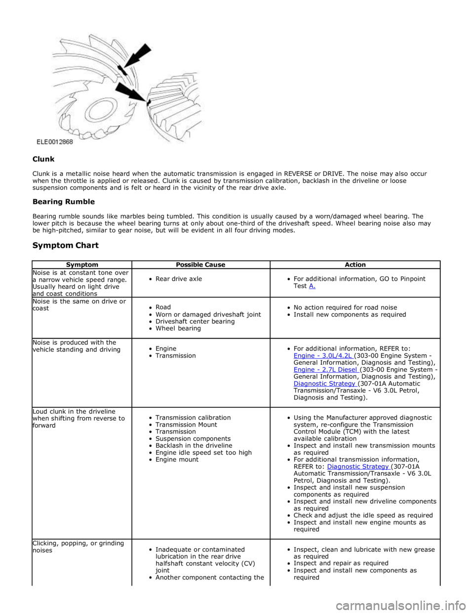
Clunk
Clunk is a metallic noise heard when the automatic transmission is engaged in REVERSE or DRIVE. The noise may also occur
when the throttle is applied or released. Clunk is caused by transmission calibration, backlash in the driveline or loose
suspension components and is felt or heard in the vicinity of the rear drive axle.
Bearing Rumble
Bearing rumble sounds like marbles being tumbled. This condition is usually caused by a worn/damaged wheel bearing. The
lower pitch is because the wheel bearing turns at only about one-third of the driveshaft speed. Wheel bearing noise also may
be high-pitched, similar to gear noise, but will be evident in all four driving modes.
Symptom Chart
Symptom Possible Cause Action Noise is at constant tone over
a narrow vehicle speed range.
Usually heard on light drive
and coast conditions
Rear drive axle
For additional information, GO to Pinpoint
Test A. Noise is the same on drive or
coast
Road
Worn or damaged driveshaft joint
Driveshaft center bearing
Wheel bearing
No action required for road noise
Install new components as required Noise is produced with the
vehicle standing and driving
Engine
Transmission
For additional information, REFER to:
Engine - 3.0L/4.2L (303-00 Engine System - General Information, Diagnosis and Testing),
Engine - 2.7L Diesel (303-00 Engine System - General Information, Diagnosis and Testing),
Diagnostic Strategy (307-01A Automatic Transmission/Transaxle - V6 3.0L Petrol,
Diagnosis and Testing). Loud clunk in the driveline
when shifting from reverse to
forward
Transmission calibration
Transmission Mount
Transmission
Suspension components
Backlash in the driveline
Engine idle speed set too high
Engine mount
Using the Manufacturer approved diagnostic
system, re-configure the Transmission
Control Module (TCM) with the latest
available calibration
Inspect and install new transmission mounts
as required
For additional transmission information,
REFER to: Diagnostic Strategy (307-01A Automatic Transmission/Transaxle - V6 3.0L
Petrol, Diagnosis and Testing).
Inspect and install new suspension
components as required
Inspect and install new driveline components
as required
Check and adjust the idle speed as required
Inspect and install new engine mounts as
required Clicking, popping, or grinding
noises
Inadequate or contaminated
lubrication in the rear drive
halfshaft constant velocity (CV)
joint
Another component contacting the
Inspect, clean and lubricate with new grease
as required
Inspect and repair as required
Inspect and install new components as
required
Page 586 of 3039
TEST
CONDITIONS DETAILS/RESULTS/ACTIONS D1: CHECK FOR SPONGY PEDAL (ENGINE OFF) 1 Check for a firm brake pedal. Is the brake pedal effort and brake pedal travel normal? Yes
No action is required, vehicle is OK.
No
GO to D2. D2: CHECK BRAKE PEDAL RESERVE (ENGINE OFF) 1 Pump the brake pedal 10 times and hold on the final application. Does the brake pedal feel firm on final application? Yes
GO to D3. No
Bleed the brake system.
REFER to: Brake System Bleeding (206-00 Brake System - General Information, General Procedures). D3: CHECK BRAKE PEDAL RESERVE (ENGINE ON) 1 With engine running at idle speed. 2 Apply the brake pedal lightly three or four times. 3 Wait 15 seconds for the vacuum to recover. 4 Push down on the brake pedal until it stops moving downward or an increased resistance to the brake pedal travel occurs. 5 Hold the brake pedal in the applied position while increasing the engine speed to 2000 revs/min. 6 Release the accelerator pedal. Does the brake pedal move downward as the engine speed returns to idle? Yes
GO to D4. No
Check the vacuum to brake booster. D4: CHECK BRAKE FLUID LEVEL 1 Check the brake master cylinder reservoir fluid level. Is the fluid level OK? Yes
Bleed the brake system.
REFER to: Brake System Bleeding (206-00 Brake System - General Information, General Procedures). Re-test the system for normal operation.
No
Check for leaking brake system and rectify as required. Add fluid and bleed the brake system.
REFER to: Brake System Bleeding (206-00 Brake System - General Information, General Procedures). Re-test the system for normal operation.
PINPOINT TEST E : THE PEDAL GOES DOWN FAST TEST
CONDITIONS DETAILS/RESULTS/ACTIONS E1: ROAD TEST VEHICLE 1 Road test the vehicle and apply the brake pedal. Is the brake pedal effort and brake pedal travel normal? Yes
No action required, vehicle is OK.
No
GO to E2. E2: CHECK BRAKE PEDAL TRAVEL-PRESSURIZE SYSTEM 1 Pump the brake pedal rapidly (five times). Does the brake pedal travel build up and then hold? Yes
Bleed the brake system.
REFER to: Brake System Bleeding (206-00 Brake System - General Information, General Procedures). Re-test the system for normal operation.
No
GO to E3. E3: CHECK FOR BRAKE SYSTEM LEAKS Is the alignment within specification?
Yes
No action is required, vehicle is OK.
No
Adjust the alignment as required. REFER to:
Front Subframe - 2.7L Diesel (502-00, Removal and Installation),
Front Subframe - V6 3.0L Petrol (502-00 Uni-Body, Subframe and Mounting System, Removal and Installation),
Front Subframe - 4.2L (502-00, Removal and Installation).
Page 588 of 3039

Inspect the brake booster, rubber grommet, and all vacuum plumbing for cracks, holes, damaged connections, or missing clamps. 4 Pump the brake pedal several times to exhaust the vacuum. Push down on the brake pedal and hold. Does the brake pedal move down when the engine is started?
Yes
Vacuum system is OK.
No
GO to G4. G4: CHECK POWER BRAKE BOOSTER VALVE 1 Check the brake booster valve. For additional information, refer to Brake Booster component test in this section. Is the power brake booster valve OK?
Yes
Check the brake booster. For additional information, refer to Brake Booster component test in this
section. Install a new brake booster as required. REFER to:
Brake Booster (206-07 Power Brake Actuation, Removal and Installation), Brake Booster - RHD (206-07, Removal and Installation).
Re-test the system for normal operation.
No
Install a new brake booster valve. Re-test the system for normal operation.
PINPOINT TEST H : BRAKE LOCKUP DURING LIGHT BRAKE PEDAL FORCE TEST
CONDITIONS DETAILS/RESULTS/ACTIONS H1: TEST BRAKE LOCKUP 1 Road test the vehicle and apply the brake pedal lightly. Do the brakes lockup?
Yes
GO to H2. No
No action required, vehicle is OK. H2: INSPECT BRAKE PADS 1 Inspect brake pads for contamination, correct installation, damage and type. Has a concern been identified?
Yes
Correctly install or install new brake pads as required. REFER to:
Brake Pads - Vehicles With: Standard Brakes (206-03A Front Disc Brake - V6 3.0L Petrol, Removal and Installation),
Brake Pads - Vehicles With: High Performance Brakes (206-03A Front Disc Brake - V6 3.0L Petrol, Removal and Installation),
Brake Pads (206-04A Rear Disc Brake - V6 3.0L Petrol, Removal and Installation), Brake Pads - Vehicles With: High Performance Brakes (206-04, Removal and Installation).
Re-test the system for normal operation.
No
GO to H3. H3: INSPECT BRAKE CALIPERS 1 Inspect brake calipers for binding, leaking or sticking. Has a concern been identified?
Yes
Correctly install or install new brake calipers as required. REFER to:
Brake Caliper - Vehicles With: Standard Brakes (206-03A Front Disc Brake - V6 3.0L Petrol, Removal and Installation),
Brake Caliper - Vehicles With: High Performance Brakes (206-03A Front Disc Brake - V6 3.0L Petrol, Removal and Installation),
Brake Caliper (206-04A Rear Disc Brake - V6 3.0L Petrol, Removal and Installation), Brake Caliper - Vehicles With: High Performance Brakes (206-04, Removal and Installation).
Re-test the system for normal operation.
No
No action required, vehicle is OK.
PINPOINT TEST I : BRAKES DRAG TEST
CONDITIONS DETAILS/RESULTS/ACTIONS I1: ROAD TEST VEHICLE 1 Road test the vehicle and apply the brakes. Are the brakes functioning correctly? Yes
No action required, vehicle is OK.
No
GO to I2. I2: CHECK BRAKE CALIPERS 1 Check the front and rear calipers pistons and pins for binding, leaking or sticking.
Page 589 of 3039
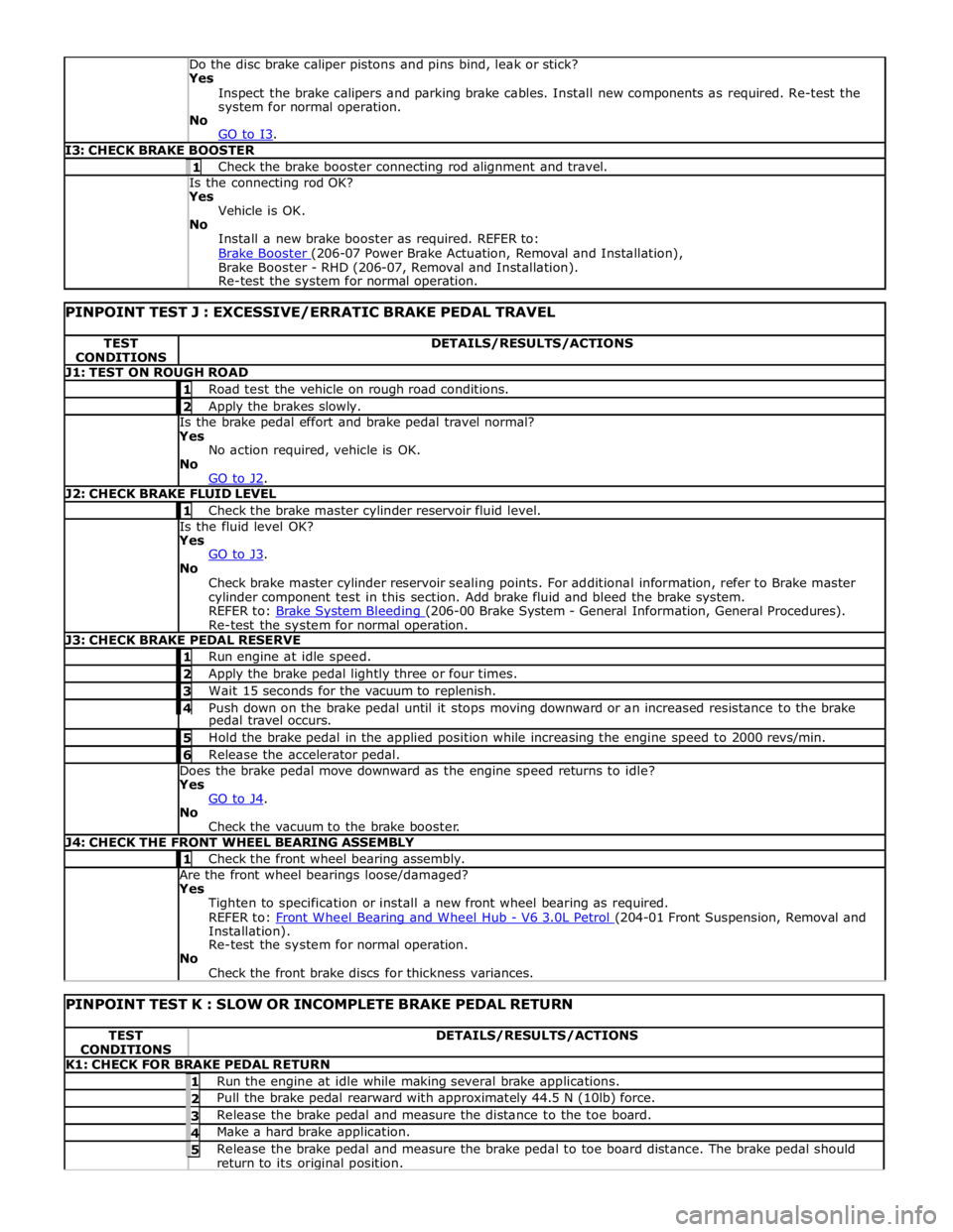
Yes
Inspect the brake calipers and parking brake cables. Install new components as required. Re-test the
system for normal operation.
No
GO to I3. I3: CHECK BRAKE BOOSTER 1 Check the brake booster connecting rod alignment and travel. Is the connecting rod OK? Yes
Vehicle is OK.
No
Install a new brake booster as required. REFER to:
Brake Booster (206-07 Power Brake Actuation, Removal and Installation), Brake Booster - RHD (206-07, Removal and Installation).
Re-test the system for normal operation.
PINPOINT TEST J : EXCESSIVE/ERRATIC BRAKE PEDAL TRAVEL TEST
CONDITIONS DETAILS/RESULTS/ACTIONS J1: TEST ON ROUGH ROAD 1 Road test the vehicle on rough road conditions. 2 Apply the brakes slowly. Is the brake pedal effort and brake pedal travel normal?
Yes
No action required, vehicle is OK.
No
GO to J2. J2: CHECK BRAKE FLUID LEVEL 1 Check the brake master cylinder reservoir fluid level. Is the fluid level OK?
Yes
GO to J3. No
Check brake master cylinder reservoir sealing points. For additional information, refer to Brake master
cylinder component test in this section. Add brake fluid and bleed the brake system.
REFER to: Brake System Bleeding (206-00 Brake System - General Information, General Procedures). Re-test the system for normal operation. J3: CHECK BRAKE PEDAL RESERVE 1 Run engine at idle speed. 2 Apply the brake pedal lightly three or four times. 3 Wait 15 seconds for the vacuum to replenish. 4 Push down on the brake pedal until it stops moving downward or an increased resistance to the brake pedal travel occurs. 5 Hold the brake pedal in the applied position while increasing the engine speed to 2000 revs/min. 6 Release the accelerator pedal. Does the brake pedal move downward as the engine speed returns to idle?
Yes
GO to J4. No
Check the vacuum to the brake booster. J4: CHECK THE FRONT WHEEL BEARING ASSEMBLY 1 Check the front wheel bearing assembly. Are the front wheel bearings loose/damaged?
Yes
Tighten to specification or install a new front wheel bearing as required.
REFER to: Front Wheel Bearing and Wheel Hub - V6 3.0L Petrol (204-01 Front Suspension, Removal and Installation).
Re-test the system for normal operation.
No
Check the front brake discs for thickness variances.
PINPOINT TEST K : SLOW OR INCOMPLETE BRAKE PEDAL RETURN TEST
CONDITIONS DETAILS/RESULTS/ACTIONS K1: CHECK FOR BRAKE PEDAL RETURN 1 Run the engine at idle while making several brake applications. 2 Pull the brake pedal rearward with approximately 44.5 N (10lb) force. 3 Release the brake pedal and measure the distance to the toe board. 4 Make a hard brake application. 5 Release the brake pedal and measure the brake pedal to toe board distance. The brake pedal should return to its original position.
Page 590 of 3039

Does the brake pedal return to its original position? Yes
No action required, vehicle is OK.
No
GO to K2. K2: CHECK FOR BRAKE PEDAL BINDING 1 Disconnect the brake booster from the brake pedal. Check the brake pedal to ensure free operation. Is the brake pedal operating freely? Yes
Install a new brake booster as required. REFER to:
Brake Booster (206-07 Power Brake Actuation, Removal and Installation), Brake Booster - RHD (206-07, Removal and Installation).
Re-test the system for normal operation.
No
Repair or install new brake pedal. Re-test the system for normal operation. Component Tests
Brake Booster
1. Check all hoses and connections. All unused vacuum connectors should be capped. Hoses and their connections should
be correctly secured and in good condition with no holes and no collapsed areas. Inspect the valve on the brake booster
for damage.
2. Check the hydraulic brake system for leaks or low fluid.
3. With the automatic transmission in PARK, stop the engine and apply the parking brake. Pump the brake pedal several
times to exhaust all vacuum in the system. With the engine switched off and all vacuum in the system exhausted,
apply the brake pedal and hold it down. Start the engine. If the vacuum system is operating, the brake pedal will tend
to move downward under constant foot pressure. If no motion is felt, the vacuum booster system is not functioning.
4. Remove the vacuum hose from the brake booster. Manifold vacuum should be available at the brake booster end of the
hose with the engine at idle speed and the automatic transmission in PARK. Make sure that all unused vacuum outlets
are correctly capped, hose connectors are correctly secured and vacuum hoses are in good condition. When it is
established that manifold vacuum is available to the brake booster, connect the vacuum hose to the brake booster and
repeat Step 3. If no downward movement of the brake pedal is felt, install a new brake booster.
5. Operate the engine for a minimum of 10 seconds at a fast idle. Stop the engine and allow the vehicle to stand for 10
minutes. Then, apply the brake pedal with approximately 89 N (20lb) of force. The pedal feel (brake application) should
be the same as that noted with the engine running. If the brake pedal feels hard (no power assist), install a new valve
and then repeat the test. If the brake pedal still feels hard, install a new brake booster. If the brake pedal movement
feels spongy, bleed the brake system.
REFER to: Brake System Bleeding (206-00 Brake System - General Information, General Procedures). Brake Master Cylinder
Usually, the first and strongest indicator of anything wrong in the brake system is a feeling through the brake pedal. In
diagnosing the condition of the brake master cylinder, check pedal feel as evidence of a brake concern. Check for brake warning
lamp illumination and the brake fluid level in the brake master cylinder reservoir.
Normal Conditions
The following conditions are considered normal and are not indications that the brake master cylinder is in need of repair.
Modern brake systems are designed to produce a pedal effort that is not as hard as in the past. Complaints of light
pedal efforts should be compared to the pedal efforts of another vehicle of the same model and year.
The fluid level will fall with brake pad wear.
Abnormal Conditions
Changes in the brake pedal feel or brake pedal travel are indicators that something could be wrong in the brake system. The
diagnostic procedure and techniques use brake pedal feel, warning indicator illumination and low brake fluid level as indicators
to diagnosing brake system concerns. The following conditions are considered abnormal and indicate that the brake master
cylinder is in need of repair:
NOTE: Prior to carrying out any diagnosis, make sure the brake system warning indicator is functional.
Brake pedal goes down fast. This could be caused by an external or internal leak.
Brake pedal goes down slowly. This could be caused by an internal or external leak.
Brake pedal is low or feels spongy. This condition may be caused by no fluid in the brake master cylinder, reservoir cap
vent holes clogged or air in the hydraulic system.
Brake pedal effort is excessive. This may be caused by a bind or obstruction in the pedal/linkage, a faulty non-return
valve, booster or insufficient booster vacuum.
Rear brakes lock up during light pedal force. This may be caused by damaged brake pads, a partially applied parking
brake, a damaged ABS sensor or bearing failure.
Brake pedal effort erratic. This condition could be caused by the brake booster or incorrectly installed brake pads.
Brake warning indicator is on. This may be caused by low fluid level or float assembly damaged. www.JagDocs.com
Page 725 of 3039

With the control valve (7) OPEN and the engine idling, the following system pressures may be checked:
During turning when static (dry parking pressure).
When the steering is held on full lock (maximum system pressure or pressure relief).
With the steering at rest (idle pressure or back pressure).
CAUTIONS:
To avoid excessive heating of the power steering pump when checking the pressure, do not close the valve for more than
5 seconds maximum.
When checking the pump pressure DO NOT drive the vehicle with the test equipment installed.
With the control valve (7) CLOSED the power steering pump maximum output pressure can be checked.
Removing Test Equipment
To remove the test equipment:
Install a hose clamp on the reservoir to power steering pump hose.
Removing the test equipment is a reversal of the installation instructions.
Install a new 'O' ring seal (9) to the power steering pump high pressure outlet to hose connection.
Install the original hose to the power steering pump.
Remove the clamp from the reservoir to the power steering pump hose.
Top-up the reservoir fluid.
Bleed the power steering system.
REFER to: Power Steering System Bleeding (211-00 Steering System - General Information, General Procedures).
Description of Terms General Steering System Noises
Boom
Rhythmic sound like a drum roll or distant thunder. May cause pressure on the ear drum.
Buzz
Low-pitched sound, like a bee. Usually associated with vibrations.
Chatter
Rapidly repeating metallic sound.
Chuckle
Rapid noise that sounds like a stick against the spokes of a spinning bicycle wheel.
Chirp
High pitched rapidly repeating sound, like chirping birds.
Click
Light sound, like a ball point pen being clicked.
Click/Thump
Heavy metal-to-metal sound, like a hammer striking steel.
Grind
Abrasive sound, like a grinding wheel or sandpaper rubbing against wood.
Groan/Moan
Continuous, low-pitched humming sound.
Groan/Howl
Low, guttural sound, like an angry dog.
Hiss
Continuous sound like air escaping from a tire valve.
Page 1372 of 3039
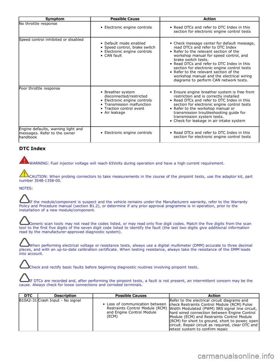
Symptom Possible Cause Action No throttle response
Electronic engine controls
Read DTCs and refer to DTC Index in this
section for electronic engine control tests Speed control inhibited or disabled
Default mode enabled
Speed control, brake switch
Electronic engine controls
CAN fault
Check message center for default message,
read DTCs and refer to DTC Index
Refer to the relevant section of the
workshop manual for speed control, and
brake switch tests.
Read DTCs and refer to DTC Index in this
section for electronic engine control tests
Refer to the relevant section of the
workshop manual and the electrical wiring
diagrams to perform CAN network tests. Poor throttle response
Breather system
disconnected/restricted
Electronic engine controls
Transmission malfunction
Traction control event
Air leakage
Ensure engine breather system is free from
restriction and is correctly installed
Read DTCs and refer to DTC Index in this
section for electronic engine control tests
Refer to the workshop manual or
transmission troubleshooting guide for
transmission system tests.
Check for leakage in air intake system Engine defaults, warning light and
messages. Refer to the owner
handbook
Electronic engine controls
Read DTCs and refer to DTC Index in this
section for electronic engine control tests DTC Index
WARNING: Fuel injector voltage will reach 65Volts during operation and have a high current requirement.
CAUTION: When probing connectors to take measurements in the course of the pinpoint tests, use the adaptor kit, part
number 3548-1358-00.
NOTES:
If the module/component is suspect and the vehicle remains under the Manufacturers warranty, refer to the Warranty
Policy and Procedure manual (section B1.2), or determine if any prior approval programme is in operation, prior to the
installation of a new module/component.
Generic scan tools may not read the codes listed, or may read only five digit codes. Match the five digits from the scan
tool to the first five digits of the seven digit code listed to identify the fault (the last two digits give additional information
read by the manufacturer-approved diagnostic system).
When performing electrical voltage or resistance tests, always use a digital multimeter (DMM) accurate to three decimal
places, and with an up-to-date calibration certificate. When testing resistance, always take the resistance of the DMM leads
into account.
Check and rectify basic faults before beginning diagnostic routines involving pinpoint tests.
If DTCs are recorded and, after performing the pinpoint tests, a fault is not present, an intermittent concern may be the
cause. Always check for loose connections and corroded terminals.
DTC Description Possible Causes Action B10A2-31 Crash Input - No signal
Loss of communication between
Restraints Control Module (RCM)
and Engine Control Module
(ECM) Refer to the electrical circuit diagrams and
check Restraints Control Module (RCM) Pulse
Width Modulated (PWM) SRS signal line circuit,
hard wired connection between Engine Control
Module (ECM) and Restraints Control Module
(RCM) for short to ground, short to power, open
circuit. Repair circuit as required, clear DTC and
retest system to confirm repair.