relay JAGUAR XJ6 1994 2.G Owner's Manual
[x] Cancel search | Manufacturer: JAGUAR, Model Year: 1994, Model line: XJ6, Model: JAGUAR XJ6 1994 2.GPages: 521, PDF Size: 17.35 MB
Page 401 of 521
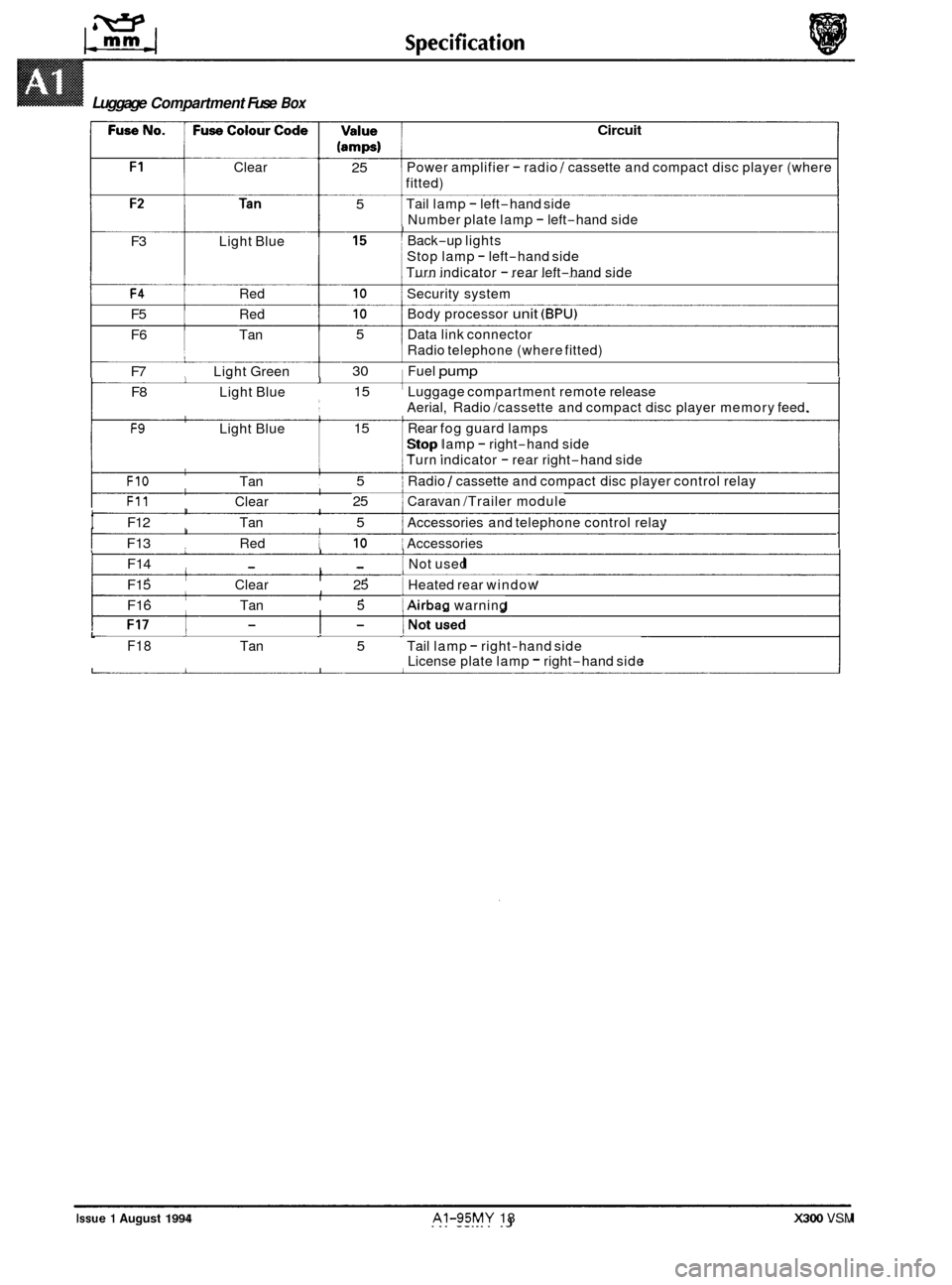
Clear
(amps) 1
Circuit
I
25 5 Power amplifier - radio / cassette and compact disc player (where
fitted)
Tail lamp
- left-hand side
Number plate lamp
- left-hand side I Back-up lights
Stop lamp
- left-hand side
Turn indicator
- rear left-hand side
F3 Light Blue
F4 Red 10 Security system
F5 Red 10 Body processor unit (BPU)
F6 Tan 5 Data link connector
F7 Light Green 30 Fuel pump
F8 Light Blue 15 Luggage compartment remote release
F9 Light Blue 15 i Rear fog guard lamps
Radio
telephone (where fitted)
1
Aerial, Radio /cassette and compact disc player memory feed.
Stop lamp
- right-hand side
1 Turn indicator - rear right-hand side I.
I FIO Tan 5 i Radio / cassette and compact disc player control relay
F11 Clear 25 1 Caravan /Trailer module I
t F12 Tan 5 ~ Accessories
and telephone control relay I I
I I I F13 Red 10 ~ Accessories 1 1 I I F14 - - I Not used 1 I I F15 Clear 25 1 Heated
rear window I I I F16 Tan 5 1 Airbag warning
Luggage Compartment Fuse Box
Issue 1 August 1994 AI-95MY 18 X300 VSM
L F18 Tan 5 Tail lamp - right-hand side
License plate lamp - right-hand side
Page 477 of 521
page e
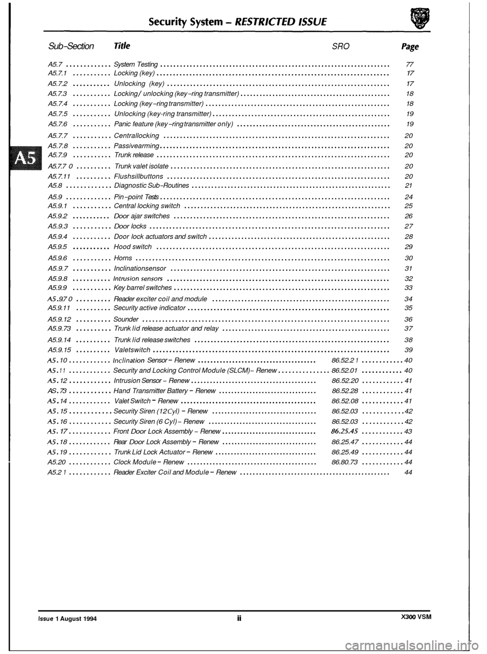
Sub-Section Title SRO
A5.7 ............. System Testing ...................................................................... 77
A5.7.1
........... Locking (key) ....................................................................... \
17
A5.7.2 ........... Unlocking (key) .................................................................... 17
A5.7.3 ........... Locking / unlocking (key-ring transmitter) ............................................... 18
A5.7.4
........... Locking (key-ring transmitter) ......................................................... 18
A5.7.5
........... Unlocking (key-ring transmitter) ....................................................... 19
A5.7.6
........... Panic feature (key-ring transmitter only) ................................................ 19
A5.7.7
........... Centrallocking ..................................................................... 20
A5.7.8
........... Passivearming ...................................................................... 20
A5.7.9
........... Trunk release ....................................................................... \
20
A5.7.7
0 .......... Trunk valet isolate ................................................................... 20
A5.7.11
.......... Flushsillbuttons .................................................................... 20
A5.9
............. Pin-point Tests ...................................................................... 24
A5.8
............. Diagnostic
Sub-Routines ............................................................. 21
A5.9.1
........... Central locking switch ............................................................... 25
A5.9.2
........... Door ajar switches .................................................................. 26
A5.9.3
........... Door locks ........................................................................\
. 27
A5.9.4
........... Door lock actuators and switch ........................................................ 28
A5.9.5
........... Hood switch ....................................................................... \
29 e
A5.9.6 ........... Horns ........................................................................\
..... 30
A5.9.7
........... Inclinationsensor ................................................................... 31
A5.9.8
........... Intrusionsensors .................................................................... 32
A5 . 9.7 0 .......... Reader exciter coil and module ....................................................... 34
A5.9.12
.......... Sounder ........................................................................\
... 36
A5.9.14
.......... Trunk lid release switches ............................................................ 38
A5.9.15
.......... Valetswitch ........................................................................\
39
A5 . 10 ............ Inclination Sensor - Renew ...................................... 86.52.2 1 ............ 40
A5 . 12 ............ Intrusion Sensor - Renew ........................................ 86.52.20 ............ 41
A5 . 14 ............ Valet Switch - Renew ........................................... 86.52.08 ............ 41
A5.9.9
........... Key
barrel switches .................................................................. 33
A5.9.11
.......... Security active indicator .............................................................. 35
A5.9.73
.......... Trunk lid release actuator and relay .................................................... 37
A5 . 11 ............ Security and Locking Control Module (SLCM) - Renew ............... 86.52.01 ............ 40
AS
. 73 ............ Hand Transmitter Battery - Renew ................................ 86.52.28 ............ 41
A5 . 15 ............ Security Siren (12 Cyl) - Renew .................................. 86.52.03 ............ 42
A5 . 16 ............ Security Siren (6 Cyl) - Renew ................................... 86.52.03 ............ 42
A5 . 17 ............ Front Door Lock Assembly - Renew ............................... 86.25.45 ............ 43
A5 . 18 ............ Rear Door Lock Assembly - Renew ............................... 86.25.47 ............ 44
Trunk Lid Lock Actuator - Renew ................................. 86.25.49 ............ 44
Clock Module - Renew ......................................... 86.80.73 ............ 44
Reader Exciter Coil and Module - Renew ............................................... 44
e
A5 . 19 ............
A5.20 ............
A5.2 1 ............
e
X300 VSM Issue 1 August 1994 ii
Page 480 of 521
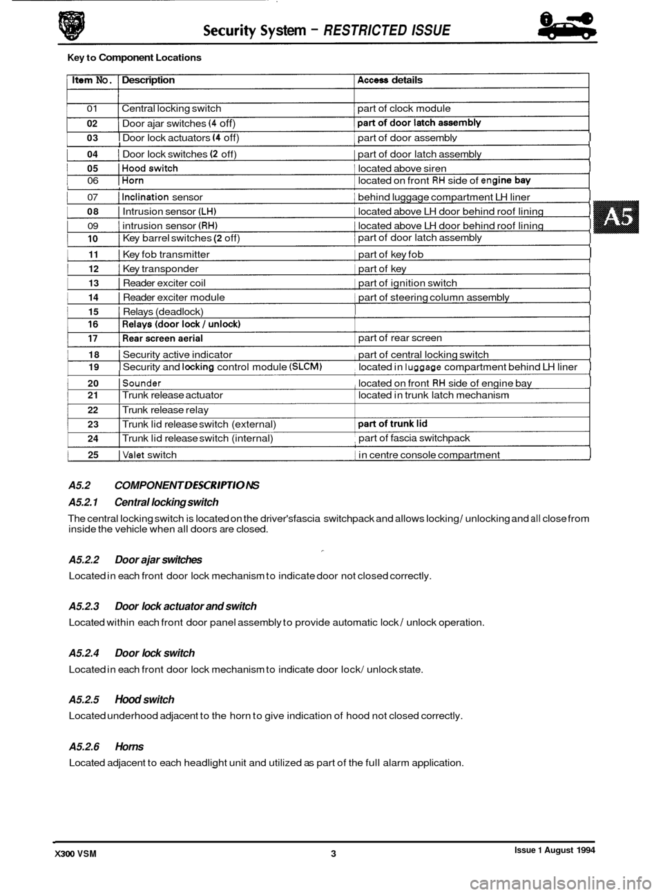
I 03 I Door lock actuators (4 off) 1 part of door assemblv I I
Issue 1 August 1994 X300 VSM 3 I
1 04 I Door lock switches (2 off) I part of door latch assembly I I
1 05 IHoodswitch 1 located above siren I I
1 06 IHorn 1 located on front RH side of en(
1 07 I Inclination sensor I behind luggage compartment LH liner I I
I 08 I Intrusion sensor (LH) I located above LH door behind roof lining I
I 09 I intrusion sensor (RH) 1 located above LH door behind roof lining I
I
1 1 part of door latch assembly I 10 I Key barrel switches (2 off)
1 11 I Key fob transmitter 1 part of key fob I I
I 12 I Key transponder 1 part of key I I
I 13 I Reader exciter coil 1 part of ignition switch I I
I 14 I Reader exciter module 1 part of steering column assembly I I
1 15 I Relays (deadlock) I I I
1 18 I Security active indicator part of central locking switch I I
I 19 I Securitv and lockina control module (SLCM) located in luaaaae compartment behind LH liner I I
1 20 ISounder , located on front RH side of engine bay I I
1 25 IValet switch 1 in centre console compartment I I
A5.2 COMPONENT DESCR/PT/O NS I
stem - RESTRICTED ISSUE
Key to Component Locations
Item No. Description Access details
01 Central locking switch part of clock module
02
1 I
Door ajar switches (4 off)
I I
part of rear screen
I 21 I Trunk release actuator located in trunk latch mechanism
22 I Trunk release relay
23
24 I Trunk lid release switch (external)
I Trunk lid release switch (internal) part of
fascia switchpack ,
A5.2.1 Central locking switch
A5.2.2 Door ajar switches
Located in each front door lock mechanism to indicate door not closed correctly.
-
The central locking switch is located on the driver'sfascia switchpack and allows locking / unlocking and all close from
inside the vehicle when all doors are closed.
A5.2.3
Located within each front door panel assembly to provide automatic lock / unlock operation.
Door lock actuator and switch
A5.2.4 Door lock switch
Located in each front door lock mechanism to indicate door lock/ unlock state.
A5.2.5 Hood switch
Located underhood adjacent to the horn to give indication of hood not closed correctly.
A5.2.6 Horns
Located adjacent to each headlight unit and utilized as part of the full alarm application.
Page 482 of 521
Security System
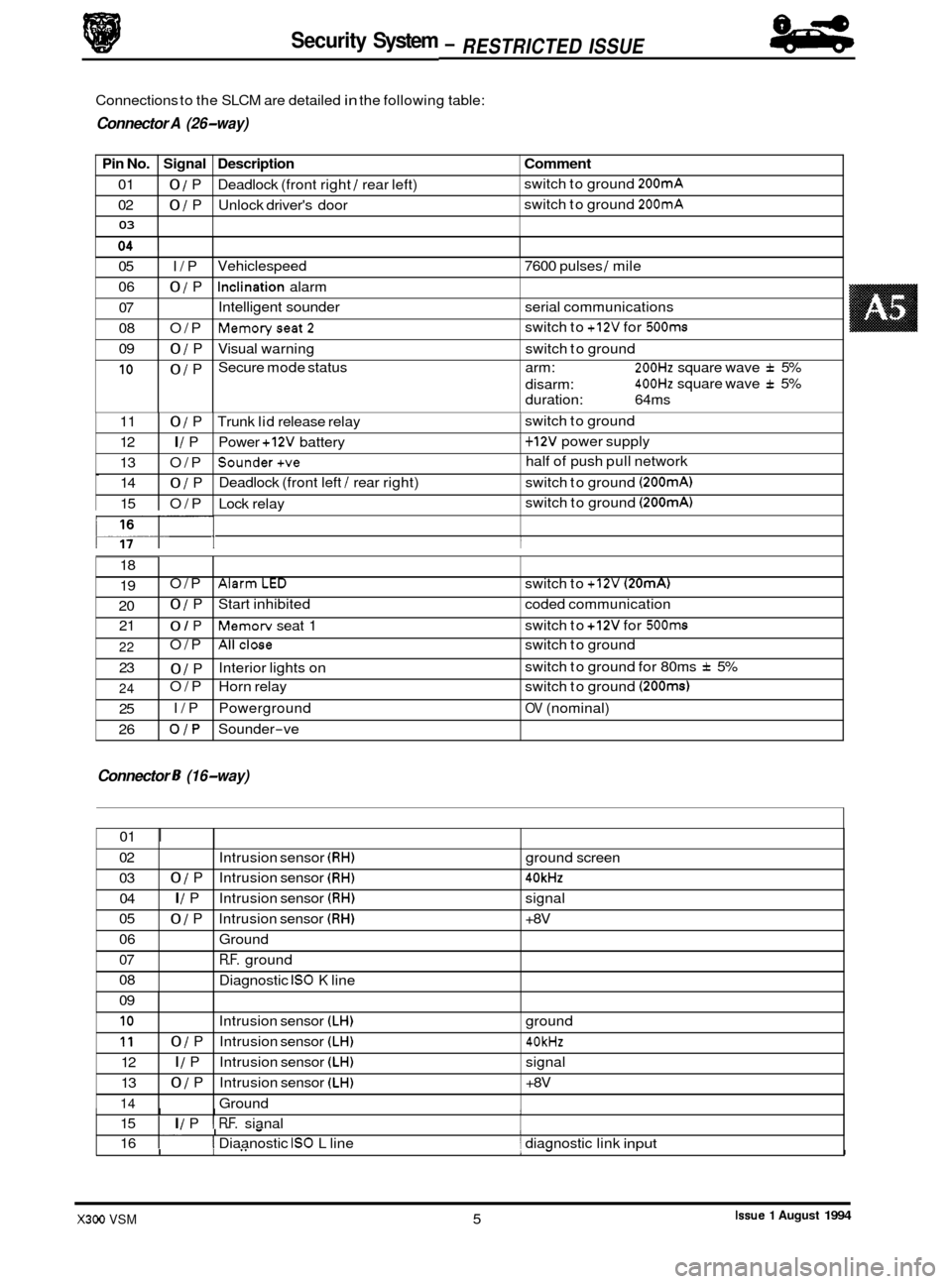
Pin No. Signal Description
01 0 / P Deadlock (front right / rear left)
02
0 / P Unlock driver's door
03
Connections to the SLCM are detailed in the following table:
9 Connector A (26-way)
Comment
switch to ground 200mA
switch to ground 200mA
05 I/P
06
0 / P
07
08 O/P
09
0 / P
10 0 / P Vehiclespeed
7600 pulses
/ mile
Inclination alarm
Intelligent sounder serial communications
Memoryseat2
Visual warning switch to ground
Secure mode status arm:
200Hz square wave f 5%
400Hz square wave f 5%
switch
to
+12V for 500ms
disarm:
duration: 64ms
0
117- I I
11 0 / P Trunk lid release relay 1 switch to ground
12
I / P Power +12V battery 1 + 12V power supply
13 O/P
Sounder+ve half of push pull network
14
0 / P Deadlock
(front left / rear right) switch to ground (200mA)
15 O/P Lock relay switch
to ground (200mA)
18
19
20 21 O/P
AlarmLED switch
to +12V (20mA)
0 / P Start inhibited coded communication
0 / P Memorv seat 1 switch
to +12V for 500ms
Connector 8 (16-way)
22
23
24
25
26 O/P
Allclose switch
to ground
0 / P
O/P Horn relay switch to ground
(200ms)
I/P Powerground OV (nominal)
OJP Sounder-ve
Interior lights
on switch
to ground for 80ms
f 5%
01
I
02
03 04
05
06
07
08
09
I I I I 15 I I / P I R.F. sianal
Intrusion
sensor
(RH) ground screen
0 / P Intrusion sensor (RH) 40kHz
I / P Intrusion sensor (RH) signal
0 / P Intrusion sensor (RH) +8V
Ground
R.F. ground
Diagnostic
IS0 K line
I. I - I 16 I I Diaanostic IS0 L line 1 diagnostic link input
10
11
12
13
14
.I
I I" 1- I
Intrusion sensor (LH) ground
0 / P Intrusion sensor (LH) 40kHz
I / P Intrusion sensor (LH) signal
0 / P Intrusion sensor (LH) +8V
Ground
Issue 1 August 1994 X300 VSM 5
84
- RESTRICTED ISSUE -
Page 498 of 521
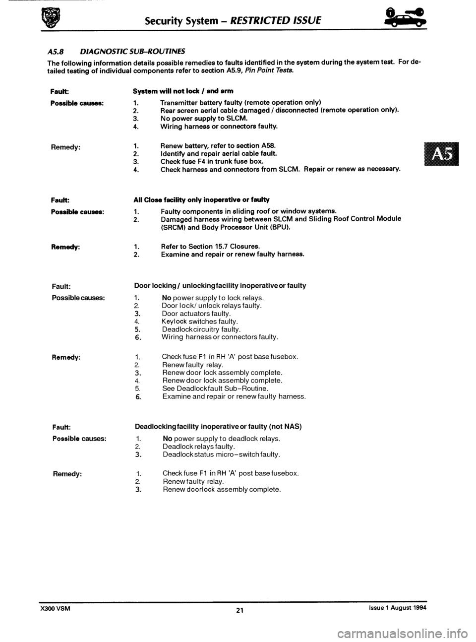
Remedy: Fault:
Possible causes:
1. No power supply to lock relays.
Door lock/ unlock relays faulty.
Door locking / unlocking facility inoperative or faulty
2.
3. Door actuators faulty.
4. Keylock switches faulty.
5. Deadlock circuitry faulty.
6. Wiring harness or connectors faulty.
Remedy: 1.
2. Renew faulty relay.
3.
4.
5. See Deadlock fault Sub-Routine.
6.
Check fuse F1 in RH 'A' post base fusebox.
Renew door lock assembly complete.
Renew door lock assembly complete.
Examine and repair or renew faulty harness.
Fault Deadlocking facility inoperative or faulty (not NAS)
Possible causes: 1. No power supply to deadlock relays.
2. Deadlock relays faulty.
3. Deadlock status micro-switch faulty.
Remedy: 1.
2. Renew faulty relay.
3. Renew doorlock assembly complete.
Check
fuse
F1 in RH 'A' post base fusebox.
Page 499 of 521

Security System - RESTRICTED lSSUE
Fault:
Possible causes:
Remedy: Fault:
Fault:
Possible causes:
Remedy:
Fault:
Possible causes:
Remedy: Intrusion
sensing inoperative
1. Faulty sensor.
2. Harness wiring or connectors faulty.
1. Renew sensor.
2. Examine and repair or renew faulty harness.
Inclination sensing inoperative
1. Faulty sensor.
2. Harness wiring or connectors faulty.
1. Renew sensor.
2. Examine and repair or renew faulty harness.
1.
2.
3.
4.
1.
2.
3.
4.
Fuel filler cap locking / unlocking faulty
No power to actuator relay.
Wiring harness or connectors faulty
Relay faulty
Actuator faulty.
Check fuse
F1 in RH 'A' post fuse box.
Examine and repair or renew faulty harness.
Renew relay.
Renew actuator.
Pan.; feature inoperative
1. Transmitter battery inoperative.
2. Rear screen aerial cable damaged / disconnected.
1. Renew battery.
2. Identify and repair aerial fault.
Fault: Central locking switch inoperative
Possible causes:
1. Harness wiring or connectors faulty.
2. Switch faulty.
Remedy: 1.
2. Renew switch.
Examine
and repair
or renew damaged harness.
X3OO VSM Issue 1 August 1994 22
Page 501 of 521
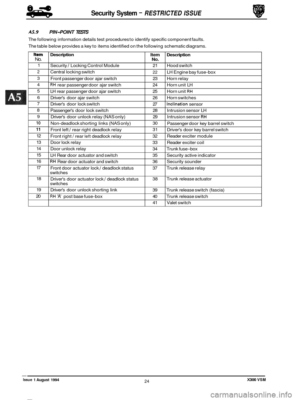
Security System - RESTRICTED ISSUE 84
eb
Description
Security / Locking Control Module
Central locking switch
Front passenger door ajar switch
RH rear passenger door ajar switch
LH rear passenger door ajar switch
Driver's door ajar switch
Driver's door lock switch
Passenger's door lock switch
Driver's door unlock relay (NAS only)
Non
-deadlock shorting links (NAS only)
Front left
/ rear right deadlock relay
Front right
/ rear left deadlock relay
Door lock relay
Door unlock relay
LH Rear door actuator and switch
RH Rear door actuator and switch
Front door actuator lock
/ deadlock status
switches
Driver's door actuator lock
/ deadlock status
switches
Driver's door unlock shorting link
RH 'A' post base fuse-box
A5.9 PIN-POINT TESTS
The following information details test procedures to identify specific component faults.
The table below provides a key to items identified on the following schematic diagrams.
Item Description No.
21 Hood switch
22 LH Engine bay fuse-box
23 Horn relay
24 Horn unit LH
25 Horn unit
RH
26 Horn switches
27
Inclination sensor
28 Intrusion sensor LH
29 Intrusion sensor
RH
30
31
32 Reader exciter module
33 Reader exciter coil
34 Trunk fuse
-box
35 Security active indicator
36 Security sounder
37 Trunk release relay
38 Trunk release actuator
39 Trunk release switch (fascia)
40 Trunk release switch
41 Valet switch
Passenger
door key barrel switch
Driver's door key barrel switch
Item No.
1
2
3
4
5
6
7
8
9
10
11
12
13
14
15
16
17
18
19
20
X300 VSM 24 Issue 1 August 1994
Page 505 of 521

Security System - RESTRICTED ISSUE 84
4b
A5.9.4 Door lock actuators and switch
1.
2.
3.
Examine fuse F1 in right hand 'A' post base fusebox, if blown determine reason for rupture and
renew.
Check continuity of harness wiring as shown on Fig.
1 below. Ensure secure ground connection
from lock/ unlock and deadlock (not N.A.S.) relay pins
4 and 9.
Remove the left hand rear seat hell board, gaining access to lock/ unlock and deadlock (not
N.A.S.) relays. Operate lock/ unlock and deadlock checking for audible relay operation. renew
suspect relays.
Release door lock and measure resistance between actuator unit pins
2 and 3, a value of
approximately
8Q should be recorded. Operate door lock and check that circuit between pins 2
and 3 is opened. Resistance across pins 1 and 3 should now be approximately 88.
4.
SI
+
SR SI I I sa VI II
I 1
J8S-1909
Fig. 1 Door Lock Actuator Circuit
*I N.A.S. only
*2 Not N.A.S.
X300 VSM Issue 1 August 1994 28
Page 507 of 521
Security System - RESTRICTED ISSUE
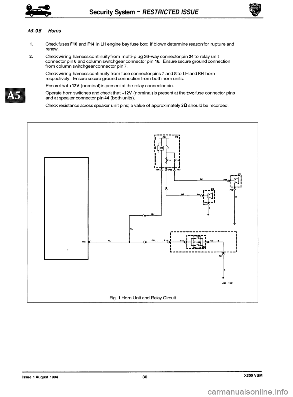
AS. 9.6 Horns
1.
2.
Check fuses FIO and F14 in LH engine bay fuse box; if blown determine reason for rupture and
renew.
Check wiring harness continuity from multi
-plug 26-way connector pin 24 to relay unit
connector pin
6 and column switchgear connector pin 16. Ensure secure ground connection
from column switchgear connector pin
7.
Check wiring harness continuity from fuse connector pins 7 and 8 to LH and RH horn
respectively. Ensure secure ground connection from both horn units.
Ensure that
+12V (nominal) is present at the relay connector pin.
Operate horn switches and check that
+12V (nominal) is present at the two fuse connector pins
and
at speaker connector pin 44 (both units).
Check resistance across speaker unit pins;
a value of approximately 2Q should be recorded.
P21.
1
r- I
$ I
I
I
I I I,, Fu
0
J86- 1911
Fig. 1 Horn Unit and Relay Circuit
X300 VSM Issue 1 August 1994 30
Page 514 of 521

1.
2.
3.
4.
5.
6.
7.
Check fuse F8 in trunk fusebox; if blown determine reason for rupture and renew.
Check harness wiring continuity between trunk fuse box connector pin
7 and relay pins 1 and 5.
Check harness wiring continuity to ground from relay connector pin 4 and actuator connector
pin
1.
Check harness wiring from multi-plug 26-way connector pin 11 to relay connector pin 2.
Check harness wiring continuity from relay connector pin 3 to actuator connector pin 2.
Measure resistance across relay connections 1 and 2; a value of 85Q should be recorded.
Measure resistance across actuator pins;
a value in the region of 20-30Q should be recorded.
PllP
1
I Ne 1
JB6 - 1918
Fig. 1 Trunk Lid Actuator and Relay Circuit
37 Issue 1 August 1994 I X300 VSM