transmission JEEP CHEROKEE 2023 Owners Manual
[x] Cancel search | Manufacturer: JEEP, Model Year: 2023, Model line: CHEROKEE, Model: JEEP CHEROKEE 2023Pages: 276, PDF Size: 12.55 MB
Page 5 of 276
3
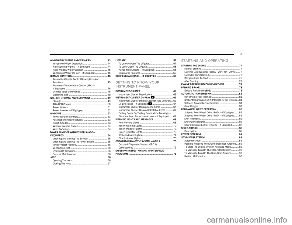
WINDSHIELD WIPERS AND WASHERS ........................... 43Windshield Wiper Operation....................................... 44
Rain Sensing Wipers — If Equipped .......................... 44
Rear Window Wiper/Washer ..................................... 45
Windshield Wiper De-Icer — If Equipped ................... 45
CLIMATE CONTROLS ..........................................................45 Automatic Climate Control Descriptions And
Functions ..................................................................... 45
Automatic Temperature Control (ATC) —
If Equipped ................................................................. 48
Climate Voice Commands .......................................... 48
Operating Tips ............................................................ 48
INTERIOR STORAGE AND EQUIPMENT ............................49 Storage ........................................................................ 49
AUX/USB Control ........................................................ 50
Power Outlets .............................................................. 51
Power Inverter — If Equipped .................................... 52
WINDOWS ...........................................................................53 Power Window Controls .............................................. 53
Automatic Window Features ..................................... 53
Reset Auto-Up.............................................................. 53
Window Lockout Switch.............................................. 54
Wind Buffeting ............................................................ 54
POWER SUNROOF WITH POWER SHADE —
IF EQUIPPED ....................................................................... 54 Opening And Closing The Sunroof ............................. 55
Opening And Closing The Power Shade .................... 55
Pinch Protect Feature ................................................. 56
Venting Sunroof .......................................................... 56
Ignition Off Operation.................................................. 56
Sunroof Maintenance ................................................. 56
HOOD ...................................................................................56 Opening The Hood ...................................................... 56
Closing The Hood ........................................................ 57 LIFTGATE .............................................................................. 57
To Unlock/Open The Liftgate ......................................57
To Lock/Close The Liftgate ......................................... 58
Hands-Free Liftgate — If Equipped ............................ 58
Cargo Area Features ................................................... 59
ROOF LUGGAGE RACK — IF EQUIPPED .......................... 60
GETTING TO KNOW YOUR
INSTRUMENT PANEL
INSTRUMENT CLUSTER ..................................................... 61 Instrument Cluster Descriptions ................................. 63
INSTRUMENT CLUSTER DISPLAY
S
.............................. 63
Instrument Cluster Display Location And Controls.... 63
Oil Life Reset — If Equipped
S
................................. 64
Instrument Cluster Display Menu Items ................... 64
Instrument Cluster Display Selectable Items ............ 67
Battery Saver On/Battery Saver Mode Message —
Electrical Load Reduction Actions — If Equipped .....67
WARNING LIGHTS AND MESSAGES ................................ 68 Red Warning Lights ..................................................... 68
Yellow Warning Lights ................................................. 70
Yellow Indicator Lights ................................................ 73
Green Indicator Lights ................................................. 73
White Indicator Lights.................................................. 74
Blue Indicator Lights.................................................... 75
ONBOARD DIAGNOSTIC SYSTEM — OBD II ..................... 75 Onboard Diagnostic System (OBD II)
Cybersecurity ...............................................................75
EMISSIONS INSPECTION AND MAINTENANCE
PROGRAMS ........................................................................ 75
STARTING AND OPERATING
STARTING THE ENGINE ..................................................... 77 Normal Starting ........................................................... 77
Extreme Cold Weather (Below –20°F Or −29°C) .... 77
Extended Park Starting ............................................... 77
If Engine Fails To Start ............................................... 78
After Starting................................................................ 78
ENGINE BREAK-IN RECOMMENDATIONS........................ 78
PARKING BRAKE ................................................................ 78 Electric Park Brake (EPB) ........................................... 78
AUTOMATIC TRANSMISSION ............................................ 81 Key Ignition Park Interlock.......................................... 81
Brake/Transmission Shift Interlock (BTSI) System ... 81
9-Speed Automatic Transmission ............................. 81
Gear Ranges ................................................................ 82
FOUR-WHEEL DRIVE OPERATION .................................... 85 1-Speed Four-Wheel Drive (4WD) — If Equipped....... 85
2-Speed Four-Wheel Drive (4WD) — If Equipped....... 85
Shift Positions.............................................................. 86
Shifting Procedures ..................................................... 86
Rear Electronic Locker System — If Equipped........... 87
SELEC-TERRAIN .................................................................. 88 Description................................................................... 88
POWER STEERING ............................................................. 88
STOP/START SYSTEM........................................................ 89 Autostop Mode ............................................................ 89
Possible Reasons The Engine Does Not Autostop .... 89
To Start The Engine While In Autostop Mode ............ 89
To Manually Turn Off The Stop/Start System............ 90
To Manually Turn On The Stop/Start System ............ 90
System Malfunction .................................................... 90
23_KL_OM_EN_USC_t.book Page 3
Page 7 of 276
5
IN CASE OF EMERGENCY
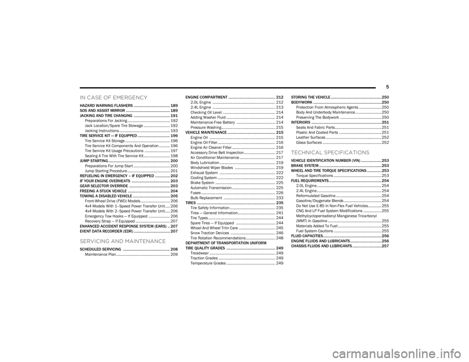
HAZARD WARNING FLASHERS ..................................... 189
SOS AND ASSIST MIRROR ............................................. 189
JACKING AND TIRE CHANGING ..................................... 191 Preparations For Jacking .......................................... 192
Jack Location/Spare Tire Stowage .......................... 192Jacking Instructions .................................................. 193
TIRE SERVICE KIT — IF EQUIPPED ................................. 196 Tire Service Kit Storage ............................................ 196
Tire Service Kit Components And Operation ........... 196Tire Service Kit Usage Precautions ......................... 197Sealing A Tire With Tire Service Kit .......................... 198
JUMP STARTING ............................................................... 200 Preparations For Jump Start .................................... 200
Jump Starting Procedure .......................................... 201
REFUELING IN EMERGENCY – IF EQUIPPED ............... 202
IF YOUR ENGINE OVERHEATS ....................................... 203
GEAR SELECTOR OVERRIDE .......................................... 203
FREEING A STUCK VEHICLE ........................................... 204
TOWING A DISABLED VEHICLE ...................................... 205 Front-Wheel Drive (FWD) Models ............................. 206
4x4 Models With 1–Speed Power Transfer Unit..... 2064x4 Models With 2–Speed Power Transfer Unit..... 206Emergency Tow Hooks — If Equipped ..................... 206
Recovery Strap — If Equipped .................................. 207
ENHANCED ACCIDENT RESPONSE SYSTEM (EARS) .. 207
EVENT DATA RECORDER (EDR) ..................................... 207
SERVICING AND MAINTENANCE
SCHEDULED SERVICING ................................................ 208 Maintenance Plan ..................................................... 209 ENGINE COMPARTMENT ................................................ 212
2.0L Engine .............................................................. 212
2.4L Engine .............................................................. 213
Checking Oil Level .................................................... 214
Adding Washer Fluid ................................................ 214
Maintenance-Free Battery ...................................... 214
Pressure Washing ..................................................... 215
VEHICLE MAINTENANCE ................................................. 215 Engine Oil ................................................................. 215Engine Oil Filter ......................................................... 216Engine Air Cleaner Filter ........................................... 216Accessory Drive Belt Inspection............................... 217
Air Conditioner Maintenance ................................... 217Body Lubrication ....................................................... 219
Windshield Wiper Blades ........................................ 219
Exhaust System ....................................................... 222
Cooling System ......................................................... 222Brake System ........................................................... 225
Automatic Transmission........................................... 225Fuses ......................................................................... 226
Bulb Replacement ................................................... 233
TIRES ................................................................................ 235 Tire Safety Information ............................................. 235
Tires — General Information..................................... 241
Tire Types .................................................................. 244
Spare Tires — If Equipped ....................................... 244
Wheel And Wheel Trim Care .................................... 245Snow Traction Devices ............................................ 246
Tire Rotation Recommendations ............................. 248
DEPARTMENT OF TRANSPORTATION UNIFORM
TIRE QUALITY GRADES .................................................. 249 Treadwear ................................................................. 249Traction Grades ........................................................ 249Temperature Grades ................................................ 249 STORING THE VEHICLE ....................................................250
BODYWORK ......................................................................250
Protection From Atmospheric Agents ...................... 250
Body And Underbody Maintenance.......................... 250
Preserving The Bodywork ......................................... 250
INTERIORS ........................................................................ 251 Seats And Fabric Parts.............................................. 251Plastic And Coated Parts .......................................... 251
Leather Surfaces ....................................................... 252
Glass Surfaces .......................................................... 252
TECHNICAL SPECIFICATIONS
VEHICLE IDENTIFICATION NUMBER (VIN) ..................... 253
BRAKE SYSTEM ................................................................ 253
WHEEL AND TIRE TORQUE SPECIFICATIONS ...............253 Torque Specifications ............................................... 253
FUEL REQUIREMENTS......................................................254 2.0L Engine................................................................ 254
2.4L Engine................................................................ 254
Reformulated Gasoline ............................................. 254Gasoline/Oxygenate Blends ..................................... 254
Do Not Use E-85 In Non-Flex Fuel Vehicles ............. 255
CNG And LP Fuel System Modifications .................. 255Methylcyclopentadienyl Manganese Tricarbonyl
(MMT) In Gasoline ..................................................... 255Materials Added To Fuel ........................................... 255
Fuel System Cautions ............................................... 255
FLUID CAPACITIES............................................................256
ENGINE FLUIDS AND LUBRICANTS ................................256
CHASSIS FLUIDS AND LUBRICANTS ..............................257
23_KL_OM_EN_USC_t.book Page 5
Page 9 of 276
7
INTRODUCTION
Dear Customer,
Congratulations on the purchase of your new Jeep®. Be assured that it represents precision workmanship, distinctive styling, and high quality.
This is a specialized utility vehicle. It can go places and perform tasks that are not intended for conventional passenger vehicles. It handles and maneuvers differently from many
passenger vehicles both on-road and off-road, so take time to become familiar with your vehicle. If equipped, the two-wheel drive version of this vehicle was designed for on-road use
only. It is not intended for off-road driving or use in other severe conditions suited for a four-wheel drive vehicle. Before you drive this vehicle, read the Owner’s Manual. Be sure you are
familiar with all vehicle controls, particularly those used for braking, steering, transmission, and transfer case shifting. Learn how your vehicle handles on different road surfaces. Your
driving skills will improve with experience. When driving off-road, or working the vehicle, don’t overload the vehicle or expect the vehicle to overcome the natural laws of physics. Always
observe federal, state, provincial and local laws wherever you drive. As with other vehicles of this type, failure to operate this vehicle correctly may result in loss of control or a collision
Úpage 123.
This Owner's Manual has been prepared with the assistance of service and engineering specialists to acquaint you with the operation and maintenance of your vehicle. It is
supplemented by customer-oriented documents. Within this information, you will find a description of the services that FCA US LLC offers to its customers as well as the details of the
terms and conditions for maintaining its validity. Please take the time to read all of these publications carefully before driving your vehicle for the first time. Following the instructions,
recommendations, tips, and important warnings in this manual will help ensure safe and enjoyable operation of your vehicle.
This Owner’s Manual describes all versions of this vehicle. Options and equipment dedicated to specific markets or versions are not expressly indicated in the text. Therefore, you should
only consider the information that is related to the trim level, engine, and version that you have purchased. Any content introduced throughout the Owner’s Information, which may or
may not be applicable to your vehicle, will be identified with the wording “If Equipped”. All data contained in this publication are intended to help you use your vehicle in the best possible
way. FCA US LLC aims at a constant improvement of the vehicles produced. For this reason, it reserves the right to make changes to the model described for technical and/or commercial
reasons. For further information, contact an authorized dealer.
When it comes to service, remember that authorized dealers know your Jeep® best, have factory-trained technicians, genuine Mopar® parts, and care about your satisfaction.
1
23_KL_OM_EN_USC_t.book Page 7
Page 11 of 276
9
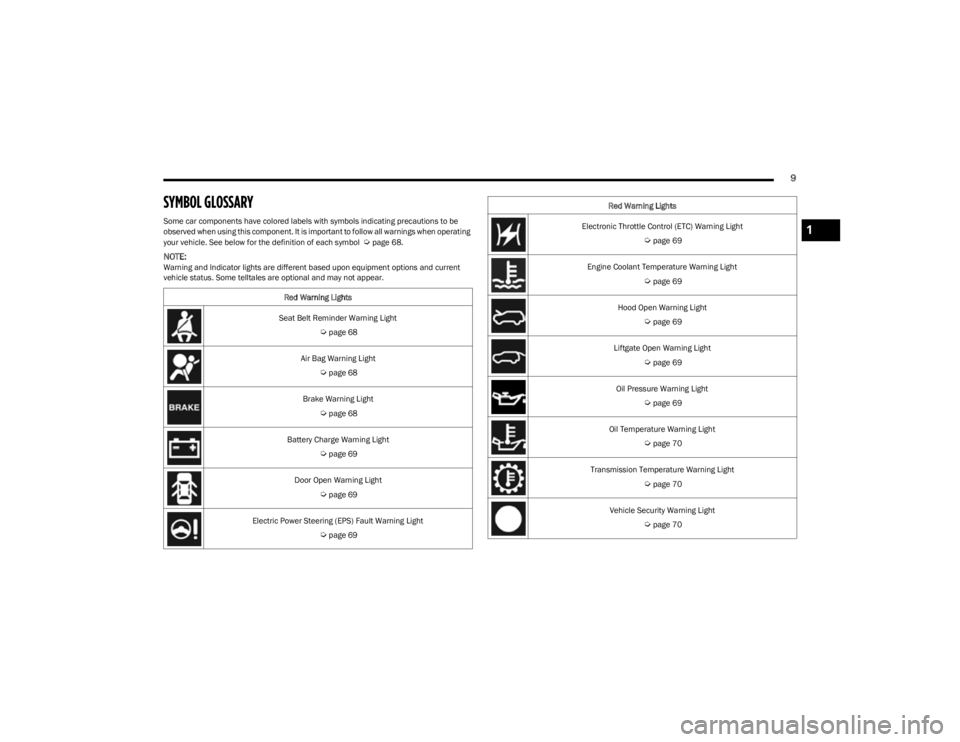
SYMBOL GLOSSARY
Some car components have colored labels with symbols indicating precautions to be
observed when using this component. It is important to follow all warnings when operating
your vehicle. See below for the definition of each symbol
Úpage 68.
NOTE:Warning and Indicator lights are different based upon equipment options and current
vehicle status. Some telltales are optional and may not appear.Red Warning Lights
Seat Belt Reminder Warning Light
Úpage 68
Air Bag Warning Light
Úpage 68
Brake Warning Light
Úpage 68
Battery Charge Warning Light
Úpage 69
Door Open Warning Light
Úpage 69
Electric Power Steering (EPS) Fault Warning Light
Úpage 69
Electronic Throttle Control (ETC) Warning Light
Úpage 69
Engine Coolant Temperature Warning Light
Úpage 69
Hood Open Warning Light
Úpage 69
Liftgate Open Warning Light
Úpage 69
Oil Pressure Warning Light
Úpage 69
Oil Temperature Warning Light
Úpage 70
Transmission Temperature Warning Light
Úpage 70
Vehicle Security Warning Light
Úpage 70
Red Warning Lights
1
23_KL_OM_EN_USC_t.book Page 9
Page 19 of 276
GETTING TO KNOW YOUR VEHICLE17
(Continued)
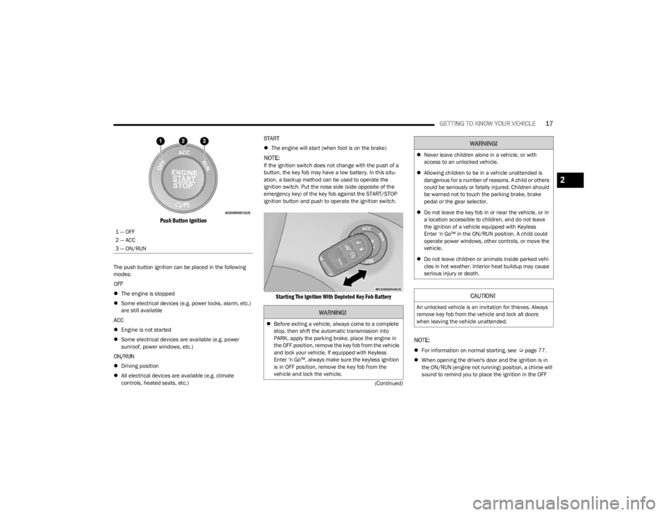
Push Button Ignition
The push button ignition can be placed in the following
modes:
OFF
The engine is stopped
Some electrical devices (e.g. power locks, alarm, etc.)
are still available
ACC
Engine is not started
Some electrical devices are available (e.g. power
sunroof, power windows, etc.)
ON/RUN
Driving position
All electrical devices are available (e.g. climate
controls, heated seats, etc.) START
The engine will start (when foot is on the brake)
NOTE:If the ignition switch does not change with the push of a
button, the key fob may have a low battery. In this situ -
ation, a backup method can be used to operate the
ignition switch. Put the nose side (side opposite of the
emergency key) of the key fob against the START/STOP
ignition button and push to operate the ignition switch.
Starting The Ignition With Depleted Key Fob Battery
NOTE:
For information on normal starting, see Úpage 77.
When opening the driver's door and the ignition is in
the ON/RUN (engine not running) position, a chime will
sound to remind you to place the ignition in the OFF
1 — OFF
2 — ACC
3 — ON/RUN
WARNING!
Before exiting a vehicle, always come to a complete
stop, then shift the automatic transmission into
PARK, apply the parking brake, place the engine in
the OFF position, remove the key fob from the vehicle
and lock your vehicle. If equipped with Keyless
Enter ‘n Go™, always make sure the keyless ignition
is in OFF position, remove the key fob from the
vehicle and lock the vehicle.
Never leave children alone in a vehicle, or with
access to an unlocked vehicle.
Allowing children to be in a vehicle unattended is
dangerous for a number of reasons. A child or others
could be seriously or fatally injured. Children should
be warned not to touch the parking brake, brake
pedal or the gear selector.
Do not leave the key fob in or near the vehicle, or in
a location accessible to children, and do not leave
the ignition of a vehicle equipped with Keyless
Enter ‘n Go™ in the ON/RUN position. A child could
operate power windows, other controls, or move the
vehicle.
Do not leave children or animals inside parked vehi -
cles in hot weather. Interior heat buildup may cause
serious injury or death.
CAUTION!
An unlocked vehicle is an invitation for thieves. Always
remove key fob from the vehicle and lock all doors
when leaving the vehicle unattended.
WARNING!
2
23_KL_OM_EN_USC_t.book Page 17
Page 38 of 276
36GETTING TO KNOW YOUR VEHICLE
To operate HomeLink®, push and release any of the
programmed HomeLink® buttons. These buttons will
activate the devices they are programmed to with each
press of the corresponding HomeLink® button.
The HomeLink® indicator light is located above the
center button.
NOTE:HomeLink® is disabled when the Vehicle Security system
is active Úpage 262.
BEFORE YOU BEGIN PROGRAMMING
H
OMELINK®
For efficient programming and accurate transmission of
the Radio Frequency (RF) signal, it is recommended that a
new battery be placed in the hand-held transmitter of the
device that is being programmed to the HomeLink®
system. Make sure your hand-held transmitter is
programmed to activate the device you are trying to
program your HomeLink® button to.
Ensure that your vehicle is parked outside of the garage
before you begin programming.
It is recommended that you erase all the channels of your
HomeLink® before you use it for the first time.
ERASING ALL THE HOMELINK®
C
HANNELS
To erase the channels, follow this procedure:
1. Place the ignition switch in the ON/RUN position.
2. Push and hold the two outside HomeLink® buttons
(I and III) for up to 20 seconds, or until the
HomeLink® indicator light flashes.
NOTE:Erasing all channels should only be performed when
programming HomeLink® for the first time. Do not erase
channels when programming additional buttons.
IDENTIFYING WHETHER YOU HAVE A
R
OLLING CODE OR NON-ROLLING CODE
D
EVICE
Before programming a device to one of your HomeLink®
buttons, you must determine whether the device has a
rolling code or non-rolling code.
Rolling Code Devices
To determine if your device has a rolling code, a good
indicator is its manufacturing date. Typically, devices
manufactured after 1995 have rolling codes. A device with
a rolling code will also have a “LEARN” or “TRAIN” button
located where the antenna is attached to the device. The
button may not be immediately visible when looking at the
device. The name and color of the button may vary slightly
by manufacturer.
NOTE:The “LEARN” or “TRAIN” button is not the button you
normally use to operate the device.
Non-rolling Code Devices
Most devices manufactured before 1995 will not have a
rolling code. These devices will also not have a “LEARN” or
“TRAIN” button.
PROGRAMMING HOMELINK® TO A
G
ARAGE DOOR OPENER
To program any of the HomeLink® buttons to activate your
garage door opener motor, proceed as follows:
NOTE:All HomeLink® buttons are programmed using this
procedure. You do not need to erase all channels when
programming additional buttons.
1. Place the ignition switch in the ON/RUN position.
2. Place the garage door opener transmitter 1 to
3 inches (3 to 8 cm) away from the HomeLink®
button you wish to program, while keeping the
HomeLink® indicator light in view.
3. Push and hold the HomeLink® button you want to program while you push and hold the garage door
opener transmitter button you are trying to replicate.
4. Continue to hold both buttons and observe the HomeLink® indicator light. The HomeLink® indicator
light will flash slowly and then rapidly. Once this
happens, release both buttons.
NOTE:Make sure the garage door opener motor is plugged in
before moving on to the rolling code/non-rolling code final
steps.
23_KL_OM_EN_USC_t.book Page 36
Page 39 of 276
GETTING TO KNOW YOUR VEHICLE37
Rolling Code Garage Door Opener Final Steps
NOTE:You have 30 seconds in which to initiate rolling code final
step 2, after completing rolling code final step 1.
1. At the garage door opener motor (in the garage),
locate the “LEARN” or “TRAIN” button. This can
usually be found where the hanging antenna wire is
attached to the garage door opener motor. Firmly
push and release the “LEARN” or “TRAIN” button.
2. Return to the vehicle and push the programmed HomeLink® button three times (holding the button
for two seconds each time). If the garage door opener
motor operates, programming is complete.
3. Push the programmed HomeLink® button to confirm that the garage door opener motor operates. If the
garage door opener motor does not operate, repeat
the final steps for the rolling code procedure.
Non-Rolling Code Garage Door Opener Final Steps
1. Push and hold the programmed HomeLink® button and observe the HomeLink® indicator light. If the
HomeLink® indicator light stays on constantly,
programming is complete.
2. Push the programmed HomeLink® button to confirm that the garage door opener motor operates. If the
garage door opener motor does not operate, repeat
the steps from the beginning.
PROGRAMMING HOMELINK® TO A
M
ISCELLANEOUS DEVICE
The procedure on how to program HomeLink® to a
miscellaneous device follows the same procedure as
programming to a garage door opener
Úpage 36. Be sure
to determine if the device has a rolling code, or non-rolling
code before beginning the programming process.
NOTE:Canadian Radio Frequency (RF) laws require transmitter
signals to time-out (or quit) after several seconds of trans -
mission, which may not be long enough for HomeLink® to
pick up the signal during programming. Similar to this
Canadian law, some U.S. gate operators are designed to
time-out in the same manner. The procedure may need to
be performed multiple times to successfully pair the
device to your HomeLink® buttons.
REPROGRAMMING A SINGLE
H
OMELINK® BUTTON
To reprogram a single HomeLink® button that has been
previously trained, without erasing all the channels,
proceed as follows. Be sure to determine whether the new
device you want to program the HomeLink® button to has
a rolling code, or non-rolling code.
1. Place the ignition in the ON/RUN position, without
starting the engine.
2. Push and hold the desired HomeLink® button until the HomeLink® indicator light begins to flash after
20 seconds. Do not release the button.
3. Without releasing the button , proceed with Step 2 in
“Programming HomeLink® To A Garage Door
Opener” and follow all remaining steps.
CANADIAN/GATE OPERATOR
P
ROGRAMMING
For programming transmitters in Canada/United States
that require the transmitter signals to “time-out” after
several seconds of transmission:
Canadian Radio Frequency (RF) laws require transmitter
signals to time-out (or quit) after several seconds of
transmission, which may not be long enough for
HomeLink® to pick up the signal during programming.
Similar to this Canadian law, some U.S. gate operators are
designed to time-out in the same manner.
WARNING!
Your motorized door or gate will open and close while
you are programming the universal transmitter. Do
not program the transmitter if people or pets are in
the path of the door or gate.
Do not run your vehicle in a closed garage or
confined area while programming the transmitter.
Exhaust gas from your vehicle contains carbon
monoxide (CO) which is odorless and colorless.
Carbon monoxide is poisonous when inhaled and
can cause you and others to be severely injured or
killed.
2
23_KL_OM_EN_USC_t.book Page 37
Page 47 of 276

GETTING TO KNOW YOUR VEHICLE45
Use of products containing wax or silicone may reduce
Rain Sensing performance.
The Rain Sensing feature can be turned on and off
using the Uconnect system
Úpage 126.
The Rain Sensing system has protection features for the
wiper blades and arms, and will not operate under the
following conditions:
Low Ambient Temperature — When the ignition is first
placed in the ON position, the Rain Sensing system will
not operate until the wiper switch is moved, vehicle
speed is greater than 3 mph (5 km/h) or the outside
temperature is greater than 32°F (0°C).
Transmission In NEUTRAL Position — When the ignition
is ON, and the transmission is in NEUTRAL, the Rain
Sensing system will not operate until the wiper switch
is moved, vehicle speed is greater than 3 mph (5 km/
h) or the gear selector is moved out of the NEUTRAL
position.
Remote Start Mode Inhibit — On vehicles equipped with
the Remote Start system, Rain Sensing wipers are not
operational when the vehicle is in the Remote Start
mode.
REAR WINDOW WIPER/WASHER
The rear wiper/washer controls are located on the
windshield wiper/washer lever on the right side of the
steering column. The rear wiper/washer is operated by
rotating a switch, located at the middle of the lever.
Rotate the center portion of the lever upward to
the first detent for intermittent operation and to
the second detent for continuous rear wiper
operation. To use the washer, push the lever forward and
hold while spray is desired. If the lever is
pushed while in the intermittent setting, the
wiper will turn on and operate for several wipe
cycles after the end of the lever is released, and then
resume the intermittent interval previously selected.
If the lever is pushed while the wiper is in the off position,
the wiper will operate for several wipe cycles, then turn off.
NOTE:As a protective measure, the pump will stop if the switch
is held for more than 20 seconds. Once the lever is
released the pump will resume normal operation.
If the rear wiper is operating when the ignition is placed in
the OFF position, the wiper will automatically return to the
parked position.
WINDSHIELD WIPER DE-ICER —
I
F EQUIPPED
Your vehicle may be equipped with a Windshield Wiper
De-Icer feature that may be activated under the following
conditions:
Activation By Front Defrost — The Windshield Wiper
De-Icer shall be activated automatically in the case of
a cold weather manual start with full front defrost, and
when the ambient temperature is below 33°F (0.6°C).
Activation By Rear Defrost — The Windshield Wiper
De-Icer shall be activated automatically when the rear
defrost is turned on and when the ambient tempera -
ture is below 33°F (0.6°C).
Activation By Remote Start Operation — When Remote
Start is active and the outside ambient temperature is
less than 33°F (0.6°C), the Windshield Wiper De-Icer will activate. Exiting Remote Start will resume its
previous operation. If the Windshield Wiper De-Icer was
active, the timer and operation will continue.
CLIMATE CONTROLS
The Climate Control system allows you to regulate the
temperature, air flow, and direction of air circulating
throughout the vehicle. The controls are located on the
touchscreen and on the instrument panel below the radio.
AUTOMATIC CLIMATE CONTROL
D
ESCRIPTIONS AND FUNCTIONS
Uconnect 4C/4C NAV With 8.4-inch Display With Automatic
Temperature Controls
MAX A/C Button
Press and release the MAX A/C button on the
touchscreen to change the current setting to
the coldest output of air. The MAX A/C indicator
illuminates when MAX A/C is on. Pressing the
button again will cause the MAX A/C operation to exit. In
2
23_KL_OM_EN_USC_t.book Page 45
Page 60 of 276
58GETTING TO KNOW YOUR VEHICLE
TO LOCK/CLOSE THE LIFTGATE
There are several different ways to close the liftgate:
Manually by grabbing the liftgate closing handle and
pulling in a downward motion to close the liftgate.
Release the handle when the liftgate takes over the
closing effort.
Key fob liftgate button (if equipped)
Hands-Free (if equipped)
Liftgate instrument panel button (if equipped)
Power Liftgate button on the pillar in the cargo area (if
equipped)
With a valid Passive Entry key fob within 5 ft (1.5 m) of the liftgate, pushing the Keyless Enter ‘n Go™ — Passive Entry
lock/push button located to the left of the Back Up
Camera will lock the vehicle only.
The power liftgate may be closed by pushing the rear
power liftgate button, located in the upper left trim in the
liftgate opening. Pushing the button will only close the
liftgate. This button cannot be used to open the liftgate.
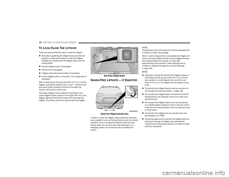
Rear Power Liftgate Button
HANDS-FREE LIFTGATE — IF EQUIPPED
Hands-Free Liftgate Activation Zone
To open or close the liftgate using hands-free activation,
use a straight in and out kicking motion under the vehicle
activation zone in the general location below the rear
license plate. Do not move your foot sideways or in a
sweeping motion or the sensors may not detect the
motion.
NOTE:The activation zone is the same for vehicles equipped with
or without a trailer tow package.
When a valid kicking motion is completed, the liftgate will
chime, the hazard lights will flash and the liftgate will open
after approximately one second, or close after
approximately three seconds. These settings can be
enabled or disabled through the Uconnect Settings
Úpage 126.
NOTE:
Opening or closing the Hands-Free Liftgate requires a
valid Passive Entry key fob within 5 ft (1.5 m) of the
door handle. If a valid Passive Entry key fob is not
within 5 ft (1.5 m), the liftgate will not respond to any
kicks.
The Hands-Free Liftgate feature may be turned on or
off through the Uconnect system
Úpage 126.
The Hands-Free Liftgate feature should be turned off
during jacking, tire changing, manual car wash, and
vehicle service.
The Hands-Free Liftgate feature can be activated by
any metallic object making a similar in-and-out motion
under the rear fascia/bumper, such as cleaning using
a metal broom.
The Hands-Free Liftgate will only operate when the
transmission is in PARK.
If anything obstructs the Hands-Free Liftgate while it is
opening or closing, the liftgate will automatically
reverse to the closed/open position, provided it meets
sufficient resistance.
23_KL_OM_EN_USC_t.book Page 58
Page 67 of 276
GETTING TO KNOW YOUR INSTRUMENT PANEL65
Speedometer
Push and release the up or down arrow button
until the speedometer menu icon is displayed in the
instrument cluster display. Push and release the OK
button to toggle units, mph or km/h (If Equipped), of the
speedometer.
Vehicle Info
Push and release the up or down arrow button
until the Vehicle Info menu icon is displayed in the
instrument cluster display. Push and release the left or
right arrow button to scroll through the information
submenus and push and release the OK button to select
or reset the submenus.
Tire Pressure : This menu option will display the current
tire pressure. A low tire will be highlighted in red for the
7 inch cluster and it will be highlighted in white text for
the 3.5 inch cluster.
Coolant Temperature : This menu option will display the
current coolant temperature of the vehicle.
Transmission Temperature : This menu will display the
current transmission temperature of the vehicle.
Oil Temperature : This menu option will display the
current oil temperature level of the vehicle.
Oil Life: This menu option will display the current oil life
of the vehicle.
Battery Voltage : This menu option will display the
current voltage level of the battery.
Driver Assist
Push and release the up or down arrow button
until the Driver Assist menu title is highlighted in the
instrument cluster display.
Adaptive Cruise Control (ACC) Menu — If Equipped
The instrument cluster display displays the current ACC
and LaneSense system settings. The information
displayed depends on the status of ACC and LaneSense.
Push the ACC on/off button (located on the steering
wheel) until one of the following displays in the instrument
cluster display:
Adaptive Cruise Control Off
When ACC is deactivated, and LaneSense is OFF, the
display will read “Adaptive Cruise Control Off.”
Adaptive Cruise Control Ready
When ACC is activated but the vehicle speed setting has
not been selected, the display will read “Adaptive Cruise
Control Ready.”
Push and release the SET + or the SET- button (located on
the steering wheel) and the following will display in the
instrument cluster display:
ACC SET
When ACC is set, the set speed will display in the
instrument cluster.
The ACC screen may display once again if any ACC activity
occurs, which may include any of the following:
Distance Setting Change
System Cancel
Driver Override
System Off
ACC Proximity Warning
ACC Unavailable Warning
NOTE:The instrument cluster display will return to the last
display selected after five seconds of no ACC display
activity
Úpage 92.
LaneSense — If Equipped
The instrument cluster display displays the current
LaneSense system settings. The information displayed
depends on LaneSense system status and the conditions
that need to be met
Úpage 109.
Fuel Economy
Push and release the up or down arrow button
until the Fuel Economy menu title is displayed in the
instrument cluster display. Toggle the left or right
arrow button to select the screen with or without current
fuel economy display. Push and hold the OK button to
reset average fuel economy feature.
Range – The display shows the estimated distance (mi
or km) that can be traveled with the fuel remaining in
the tank. When the Range value is less than 10 miles
(16 km) estimated driving distance, the Range display
will change to a “LOW FUEL” message. Adding a signif -
icant amount of fuel to the vehicle will turn off the “LOW
FUEL” message and a new Range value will display.
Range cannot be reset through the OK button.
3
23_KL_OM_EN_USC_t.book Page 65